Advertisement
Quick Links
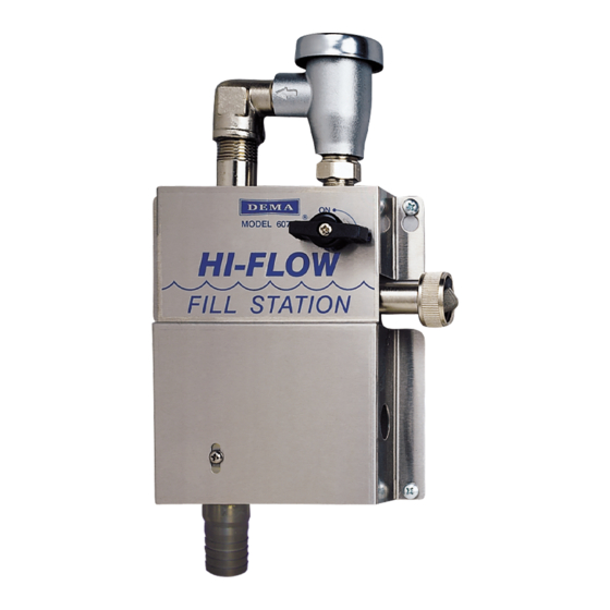
DEMA MODEL 607-3, 607-3DF & 607-3SS
I.
PARTS:
ITEM
PART NUMBER
A.
607-3, 607-3DF or 607-3SS
B.
60-47
C.
76-2-13
D.
100-16E-4
E.
61-107
F.
66-54
G.
61-9K
H.
60-52
II.
PURPOSE:
The only difference between the 607-3 and the 607-3DF is that the 607-3 is a single product unit whereas the 607-
3DF is a two product unit (the DF stands for DUAL FEED).
III.
INSTALLATION:
CAUTION: ALL WORK DONE SHOULD ADHERE TO ALL APPLICABLE PLUMBING CODES.
1. Hold assembly to wall, locate positions of mounting screws. Drill holes in wall about 1" deep. Mount
assembly to wall using screws and anchors provided.
2. Install priming ring in outlet tubing (large diameter), a few inches from one end. Slip tubing over threads of
injector, with priming ring close to the injector. Secure with tubing clamp and cut to convenient length.
3. Attach water supply hose (not provided) to water inlet and tighten.
4. To install wire hose hanger, slip outlet tubing through hose hanger.
IV.
CHEMICAL ADJUSTMENT:
CAUTION: Be careful when working with hazardous chemicals.
1. Select metering tip using Table 1 as a guide. Screw tip into inlet barb of injector.
2. Cut inlet tube to convenient length, at least 18" long to insure priming but not more than 6' (greater lifts reduce
injection capacity).
3. Slip ceramic weight over tubing and insert end with foot strainer into chemical. Attach other end to inlet barb
of injector.
Table 1: Induction readings taken at 50-psi
inlet pressure & 9 GPM.
METERING TIPS
COLOR
Clear
Purple
Yellow
Green
Pink
Turquoise
Black
Gray
Red
Blue
Brown
White
Orange
None
Induction rates may vary from product to product,
I-935
Rev. A-35120
12/01/09
HI-FLOW FILL STATION
INSTALLATION INSTRUCTIONS
PARTS CHECKLIST
DESCRIPTION
Fill Station Assembly
Outlet Tubing 10' long
Hose Clamp
Tubing & Foot Valve Assembly
Ceramic Weight
#10 Screw & Anchor Kit
Metering Tip Kit
Wire Hose Hanger
1 CPS
OZ/GAL
RATIO
0.21
606.3 – 1
0.26
496.9 – 1
0.44
288.6 – 1
0.83
155.0 – 1
0.95
134.1 – 1
1.57
81.6 – 1
2.01
63.6 – 1
2.64
48.4 – 1
3.40
37.7 – 1
4.11
31.1 – 1
5.64
22.7 – 1
7.19
17.8 – 1
8.71
14.7 – 1
14.88
8.6 – 1
607-3
607-3DF
1
1
1
1
1
1
1
2
1
2
1
1
1
1
1
1
NOTE: IN ORDER FOR UNIT
TO OPERATE PROPERLY,
FLOW RATE NEEDS TO BE 10
GPM OR GREATER.
607-3SS
1
1
1
1
1
1
1
1
Pg. 1 of 3
Advertisement

Related Manuals for DEMA 607-3


Summary of Contents for DEMA 607-3
- Page 1 60-52 Wire Hose Hanger PURPOSE: The only difference between the 607-3 and the 607-3DF is that the 607-3 is a single product unit whereas the 607- 3DF is a two product unit (the DF stands for DUAL FEED). III. INSTALLATION: CAUTION: ALL WORK DONE SHOULD ADHERE TO ALL APPLICABLE PLUMBING CODES.
- Page 2 “o”- rings, diaphragms, squeeze tubing and gaskets are considered expendable and are not covered under warranty. This warranty is extended only to the original buyer of DEMA products. If products are altered or repaired without prior approval of DEMA, this warranty will be void.
- Page 3 DEMA MODEL 607-3, 607-3DF & 607-3SS HI-FLOW FILL STATION INSTALLATION INSTRUCTIONS FOR 607-3 ONLY FOR 607-3DF ONLY PART NO. DESCRIPTION PART NO. DESCRIPTION 60-9 Siphon Breaker (1/2” NPT) 63-78 O-Ring, EPDM (O-Ring only) 95-4-1 Ball Valve (1/2” NPT MXF) 61-9- Metering Tip (Specify Color) Street Elbow (Plated) ½”...
Need help?
Do you have a question about the 607-3 and is the answer not in the manual?
Questions and answers