Table of Contents
Advertisement
Quick Links
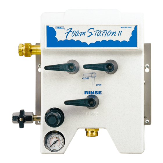
DEMA MODEL 692T FOAM STATION I
1. PARTS CHECKLIST:
ITEM
A.
B.
C.
D.
E.
F.
2. INSTALLATION:
This product is designed only to be used as described in this instruction sheet. Adhere to all warnings and
cautions identified in this document.
A. Mounting and Water Supply:
Locate mounting holes on a permanent vertical wall. Drill all holes into the drywall using a ¼" diameter bit for use with the
included #10 screw and anchor set. (If mounting unit to wood and you do not plan to use the included anchors, drill 1/8"
diameter holes.) Insert the anchors into drilled holes and hammer them into the wall until they are flush with face of wall.
Assemble the #10 screws with a phillip screwdriver into the anchors for the keyhole slots so the screw heads are sticking out
of the wall approximately ½". Mount the unit by inserting the screw heads through the keyhole slots and tightening the
screws. Secure the unit by inserting screws into the lower 2 holes.
The water inlet is equipped with a female garden hose fitting. The fitting may be removed to permit direct connection to
3/8" NPT pipe. Note: Apply pipe dope, hand tighten, and then turn 1-1/2 times with a wrench. DO NOT OVER
TIGHTEN.
WARNING: Do not use Teflon tape to seal internal plastic threads as the extra thickness of the tape may cause the
plastic to crack. Use non-welding liquid sealant instead.
WARNING: Water supply should not exceed 125 psi and water temperature must not exceed 150°F.
B. Outlet Connection:
Connect the discharge hose to the garden hose fitting. NOTE: Be sure to clamp garden hose onto wall approximately 1
ft. below the unit, (Clamps, screws, & anchors are not supplied.) Attach shut-off valve to the discharge end of the hose.
See Table 1 for hose limitations.
I-719
Rev. D-31918
INSTALLATION INSTRUCTION
Foam Station Assembly
#10 Screw & Anchor Kit Set (Total: 4 Screws & 4 Anchors)
Ceramic Weight
¼" ID Tubing & Foot Valve Assembly
Metering Tip Kit (P/N 61-9K)
Label Card
WARNING: Installations must conform to all local and national plumbing codes and use
approved backflow prevention and pressure relief devices where required.
ALWAYS DISCONNECT DISPENSER FROM WATER SOURCE WHEN DISPENSER
IS NOT IN USE.
Always read SDS for all chemicals used and follow personal protective guidelines.
TABLE 1: Outlet Garden Hose Connection
GARDEN HOSE SIZE AND
LENGTH
25' OF ¾" ID
50' OF ¾" ID
25' OF ½" ID
DESCRIPTION
MIN. PRESSURES
WATER
40 PSI
50 PSI
60 PSI
QTY.
1
1
1
1
1
1
AIR
40 PSI
40 PSI
40 PSI
Page 1 of 6
12/22/05
Advertisement
Table of Contents

Subscribe to Our Youtube Channel
Related Manuals for DEMA 692T FOAM STATION I


Summary of Contents for DEMA 692T FOAM STATION I
- Page 1 DEMA MODEL 692T FOAM STATION I INSTALLATION INSTRUCTION 1. PARTS CHECKLIST: ITEM DESCRIPTION QTY. Foam Station Assembly #10 Screw & Anchor Kit Set (Total: 4 Screws & 4 Anchors) Ceramic Weight ¼” ID Tubing & Foot Valve Assembly Metering Tip Kit (P/N 61-9K) Label Card 2.
- Page 2 DEMA MODEL 692T FOAM STATION I INSTALLATION INSTRUCTION C. Chemical Supply: WARNING: USE CARE WHEN HANDLING HAZARDOUS CHEMICALS. Place the chemical container in a convenient location not more than six feet below the Foam Station. (Greater lifts will reduce injection capabilities). The top of the container should not be above the Foam Station. Cut the vinyl tube to any convenient length that will allow the tubing to reach the bottom of the container.
- Page 3 DEMA MODEL 692T FOAM STATION I INSTALLATION INSTRUCTION knob back in to lock the setting in place. This operation must be repeated in the same order each time the 692T is shut down and restarted (water first then gradually build up air pressure).
- Page 4 Warranty DEMA products are warranted against defective material and workmanship under normal use and service for one year from the date of manufacture. This limited warranty does not apply to any products which have a normal life shorter than one year or failure and damage caused by chemicals, corrosion, improper voltage supply, physical abuse or misapplication.
- Page 5 DEMA MODEL 692T FOAM STATION I INSTALLATION INSTRUCTION FOAMER ASSEMBLY (SHOWN EXPLODED ON PAGE 6) PART NO. DESCRIPTION PART NO. DESCRIPTION 100-38 Strainer Washer 16-11 ¼” NPT Ball Valve 65-10 Swivel Coupling 24-11L Foot Strainer 65-14 Swivel Adapter 61-107 Ceramic Weight (3/8” ID Tubing)
- Page 6 DEMA MODEL 692T FOAM STATION I INSTALLATION INSTRUCTION FOAMER ASSEMBLY BREAKDOWN PART NO. DESCRIPTION PART NO. DESCRIPTION 29-18-2 5/16 Internal Snap Ring 30-5V-1 O-Ring (Viton) 29-17-2 Washer (S.S.) –Air Hose 2914 Air Nozzle 29-7 O-Ring (Viton) 93-6-2 Air Check Valve Spring 29-5P Ball 11/32”...
Need help?
Do you have a question about the 692T FOAM STATION I and is the answer not in the manual?
Questions and answers