Table of Contents
Advertisement
Quick Links
USER MANUAL
PTM 535Z 2.4 GHz Pushbutton Transmitter
PTM 535Z 2.4 GHz Pushbutton Transmitter
31 May 2016
Observe precautions! Electrostatic sensitive devices!
Patent protected:
WO98/36395, DE 100 25 561, DE 101 50 128,
WO 2004/051591, DE 103 01 678 A1, DE 10309334,
WO 04/109236, WO 05/096482, WO 02/095707,
US 6,747,573, US 7,019,241
© 2016 EnOcean | www.enocean.com
F-710-017, V1.0
PTM 535Z User Manual | v1.1 | May 2016 | Page 1/38
Advertisement
Table of Contents

Subscribe to Our Youtube Channel
Related Manuals for EnOcean PTM 535Z


Summary of Contents for EnOcean PTM 535Z
- Page 1 WO98/36395, DE 100 25 561, DE 101 50 128, WO 2004/051591, DE 103 01 678 A1, DE 10309334, WO 04/109236, WO 05/096482, WO 02/095707, US 6,747,573, US 7,019,241 © 2016 EnOcean | www.enocean.com F-710-017, V1.0 PTM 535Z User Manual | v1.1 | May 2016 | Page 1/38...
- Page 2 As far as patents or other rights of third parties are concerned, liability is only assumed for modules, not for the described applications, processes and circuits. EnOcean does not assume responsibility for use of modules described and limits its liability to the replacement of modules determined to be defective due to workmanship. Devices or sys- tems containing RF components must meet the essential requirements of the local legal au- thorities.
-
Page 3: Table Of Contents
IEEE 802.15.4 Frame Structure ..............20 PHY Header ....................21 MAC Header ....................22 MAC Trailer ....................22 MAC Payload ....................22 © 2016 EnOcean | www.enocean.com F-710-017, V1.0 PTM 535Z User Manual | v1.1 | May 2016 | Page 3/38... - Page 4 A.4.1 MAC Payload ................... 37 A.4.2 Device ID ....................37 A.4.3 Sequence Counter ................... 37 A.4.4 Command payload ................... 38 A.4.5 Telegram Signature ................. 38 © 2016 EnOcean | www.enocean.com F-710-017, V1.0 PTM 535Z User Manual | v1.1 | May 2016 | Page 4/38...
-
Page 5: General Description
ECO 200 can be either mechanically connected using two contact pairs or connect- ed to the electrical interface of PTM 535Z. Upon detection of energy pulses from the ECO 200 harvester, PTM 535Z will read the status of additional input signals (on-board meander contact, external input signals) and report the result as IEEE 802.15.4 radio telegram. -
Page 6: Technical Data
Tray / Box (10 units per tray, 10 trays per box) Ordering information Type Ordering Code Frequency PTM 535Z S3071-A535 2.4 GHz (IEE 802.15.4) © 2016 EnOcean | www.enocean.com F-710-017, V1.0 PTM 535Z User Manual | v1.0 | March 2016 | Page 6/38... -
Page 7: Functional Information
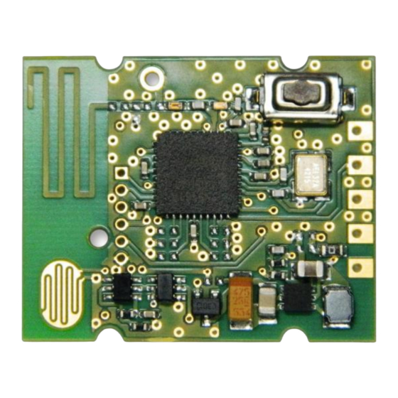
Figure 2 – Electro-dynamic powered radio transmitter device PTM 535Z Basic Functionality PTM 535Z devices contain an interface with two pair of signals (AC1 and AC2) used to con- nect an external energy generator (ECO 200). Having two contact pairs improves the me- chanical design flexibility. -
Page 8: Device Interface Signals
Figure 3 below illustrates the mechanical connection between an ECO 200 kinetic energy harvester and PTM 535Z. Note that two pairs of contacts are provided by PTM 535Z to enable two orientations of ECO 200 (spring facing down = red lines / spring facing up = yellow lines) depending on the requirements of the customer mechanical design. -
Page 9: Input Signals
USER MANUAL V1.0 PTM 535Z – 2.4 GHZ PUSHBUTTON TRANSMITTER MODULE Input signals PTM 535Z data transmits telegrams indicating the status of the following input signals: ECO 200 action direction (press or release) Press indicates a move away from the PCB (and the ECO 200 contacts) -
Page 10: Hardware Configuration Interface
For certain applications it might be desirable to transmit data telegrams without sequence counter and device security key / telegram signature. PTM 535Z can be configured to do so by populating configuration resistor R2. © 2016 EnOcean | www.enocean.com F-710-017, V1.0... -
Page 11: Hardware-Based Radio Channel Selection
2.6.2 Hardware-based radio channel selection By default, the radio channel used by PTM 535Z can be changed by the user during com- missioning as described in chapter 2.8.2.3. For certain applications it is desirable to pre-configure the radio channel in a way that it cannot be modified by the user. -
Page 12: Radio Interface
2.7.1 Antenna PTM 535Z transmits data based on an on-board PCB antenna (ANT). An external 50Ω whip antenna connected to the EXT_ANT pin can alternatively be used. Connection to the inter- nal antenna has to be cut in this case by removing capacitor CA. -
Page 13: Radio Channel Selection
HW selection (using configuration resistors, requires R1 to be populated) If configuration resistor R1 is populated then the radio channel used by PTM 535Z is fixed exclusively by the configuration resistors R3 … R6 as discussed in chapter 2.6.2. -
Page 14: Operation Modes
Commissioning mode is used to commission (learn, teach-in) PTM 535Z into a specific receiver or network. To do so, PTM 535Z will identify its capabilities and its security pa- rameters and – if required – change the radio channel it uses for telegram transmission. -
Page 15: Commissioning Mode
Commissioning mode provides two key functions: Transmission of a commissioning telegram in order to learn-in PTM 535Z into a network Radio channel selection in order to set the radio channel of PTM 535Z to that used by the network Figure 4 below shows the commissioning state chart used by PTM 535Z. -
Page 16: Entry Into Commissioning Mode
Commissioning mode is entered as soon as PTM 535Z detects an energy pulse from ECO 200 in “Press” direction and the LRN button is pressed. PTM 535Z will remain in commissioning mode as long as the LRN button is pressed when- ever ECO 200 is actuated in the “Press” direction. -
Page 17: Determining The Correct Radio Channel
It is the responsibility of the system designer to define a suitable feedback mechanism. 2.8.2.5 Storing the new radio channel and return to data mode If PTM 535Z has been successfully set to the desired radio channel then this radio channel has to be stored and operation should return to data mode. -
Page 18: Security Modes
R2. 2.9.2 Security parameters PTM 535Z transmits data is secured based on a 4 byte sequence counter, an out of the box device-unique key and a 4 byte signature calculated based on the AES128 encryption using CBC mode. -
Page 19: Number Of Redundant Telegrams
2.10 Number of redundant telegrams For most telegram types, PTM 535Z will transmit the telegram more than once (redundant transmission) in order to increase transmission reliability. The timing of the individual tele- gram transmissions is random within a 5ms window. -
Page 20: Ieee 802.15.4 Frame Structure
PTM 535Z – 2.4 GHZ PUSHBUTTON TRANSMITTER MODULE IEEE 802.15.4 Frame Structure PTM 535Z transmits radio telegrams in the 2.4 GHz band according to IEEE 802.15.4 frame structure. For detailed information about the IEEE 802.15.4 standard, please refer to the applicable specifications. -
Page 21: Phy Header
Length = 24 bytes (0x18) Standard commissioning telegram Length = 17 bytes (0x11) Standard data telegram Length = 15 bytes (0x0F) © 2016 EnOcean | www.enocean.com F-710-017, V1.0 PTM 535Z User Manual | v1.0 | March 2016 | Page 21/38... -
Page 22: Mac Header
The IEEE 802.15.4 MAC Header contains the following fields: Frame Control Field (2 byte) The Frame Control Field is set to 0x0801 in all PTM 535Z telegrams in order to identify them as data telegrams with short addresses based on version IEEE 802.15.4-2003 Sequence Number (1 byte) ... -
Page 23: Mac Payload Structure For Secure Data Telegrams
The following fields are used for secure data telegrams: Telegram Control (2 bytes) The Telegram Control field is set to 0x308C indicating that PTM 535Z uses 4 byte pay- load signature based on a device-unique key and a 4 byte sequence counter Source ID (4 bytes) ... -
Page 24: Mac Payload Structure For Secure Commissioning Telegrams
The Device Type field is set to 0x02 by PTM 535Z Device Options (2 bytes) The Device Options field is set to 0xF281 by PTM 535Z when operating in AES128 secure mode with authentication. Device-unique Security Key (16 bytes) ... -
Page 25: Mac Payload Structure For Standard Data Telegrams
4 byte ID uniquely identifying each PTM 535Z device Command (1 byte) This is a one byte field which identifies the state of the different input of PTM 535Z. For the encoding please see Table 2. © 2016 EnOcean | www.enocean.com F-710-017, V1.0... -
Page 26: Mac Payload For Standard Commissioning Telegrams
Source ID (4 bytes) The Source ID field contains a 4 byte ID uniquely identifying each PTM 535Z device Commissioning Command (1 byte) The Commissioning Command field is set to 0xE0 by PTM 535Z Device Type (1 byte) ... -
Page 27: Device Integration
USER MANUAL V1.0 PTM 535Z – 2.4 GHZ PUSHBUTTON TRANSMITTER MODULE Device Integration PTM 535Z is designed for integration with ECO 200 kinetic energy harvesters. EnOcean can provide mechanical reference designs upon request. © 2016 EnOcean | www.enocean.com F-710-017, V1.0... -
Page 28: Application Information
0.5 m. Duty Cycle PTM 535Z is designed for manually activated systems. In order to comply with duty cycle limitations, it shall not be used to transmit telegrams more often than 10.000 times per hour. -
Page 29: Regulatory Information
PTM 535Z – 2.4 GHZ PUSHBUTTON TRANSMITTER MODULE REGULATORY INFORMATION PTM 535Z has been certified according to applicable regulations. Changes or modifications not expressly approved by EnOcean could void the user's authori- ty to operate the equipment. FCC (United States) Certification PTM 535Z has been certified according to FCC rules. -
Page 30: Fcc (United States) Regulatory Statement
(1) this device may not cause harmful interference, and (2) this device must accept any interference received, including interference that may cause undesired operation. © 2016 EnOcean | www.enocean.com F-710-017, V1.0 PTM 535Z User Manual | v1.0 | March 2016 | Page 30/38... -
Page 31: Ic (Industry Canada) Certification
PTM 535Z has been certified according to IC rules. 6.2.1 IC (Industry Canada) Labeling Requirements OEM wishing to use PTM 535Z under limited modular approval conditions must sign the OEM Limited Modular Approval Agreement with EnOcean The Original Equipment Manufacturer (OEM) must ensure that IC labeling requirements are met. -
Page 32: Ic (Industry Canada) Regulatory Statement
IC (Industry Canada) Regulatory Statement This device complies with Industry Canada licence-exempt RSS standard(s). The end product into which PTM 535Z is assembled must provide a clearly readable label with the following text: „Contains IC ID: SZV-PTM535Z“ Operation is subject to the following two conditions:... -
Page 33: A Understanding Ptm 535Z Telegram Structure
PTM 535Z – 2.4 GHZ PUSHBUTTON TRANSMITTER MODULE Understanding PTM 535Z telegram structure This appendix describes – purely for reference purposes – how to analyse the PTM 535Z radio telegram structure using the TI CC2531EMK packet sniffer (USB dongle) on a Win- dows 7 based system. -
Page 34: Configuration
“Capturing device” tab and in the “RF device:” footer line as shown in Figure 12 below. Figure 12 – Main window TI SmartRF Packet Sniffer © 2016 EnOcean | www.enocean.com F-710-017, V1.0 PTM 535Z User Manual | v1.0 | March 2016 | Page 34/38... - Page 35 “MAC Header”, “Data” and “Footer” fields are selected and that the “LQI/RSSI” drop-down list is set to “RSSI”. Figure 14 – Payload selection The TI SmartRF Packet Sniffer is now ready. © 2016 EnOcean | www.enocean.com F-710-017, V1.0 PTM 535Z User Manual | v1.0 | March 2016 | Page 35/38...
-
Page 36: Data Capture
) to automatically select the most recent data telegram. Then press a button of PTM 535Z. You should now see the captured radio telegrams (PTM 535Z sends several redundant radio telegrams per user action). Figure 15 – Captured telegram data ©... -
Page 37: Interpretation Of The Telegram Data
A.4.3 Sequence Counter The sequence counter is used to uniquely identify each telegram in order to avoid telegram replay. The sequence counter is 4 byte long and only present if PTM 535Z operates in se- cure mode. In the case of a secure data telegram, the sequence counter is located at byte 6…9 of the... -
Page 38: Command Payload
PTM 535Z secure data telegrams can be authenticated via a signature. This signature is 4 byte long and only present if PTM 535Z operates in secure mode. It is calculated based on the private key (unique for each device), the data payload and a 4 byte sequence counter (which is incremented for each transmitted radio telegram).
Need help?
Do you have a question about the PTM 535Z and is the answer not in the manual?
Questions and answers