Table of Contents
Advertisement
Advertisement
Table of Contents

Related Manuals for Radian RM-111


Summary of Contents for Radian RM-111
- Page 1 Radian Research, Inc. RM-111 Automated Comparator...
- Page 2 Radian Research, Inc. RM-111 Automated Comparator Radian Research reserves the right to change 944012.B any information provided within this document without notice. 11-14...
-
Page 4: Table Of Contents
Environmental ......................8 Accuracy ........................9 Inputs (Ports A, B, C and D) ..................9 Outputs (Port D Only) ....................10 Output Accessories ....................10 RM-111 Keypad Conventions ........12 Menu Structure ............15 Main Menu ........................15 Detailed Description of Menu Items ................19 Inputs ..............22 Reference Standards (Open Collector) ...............22... -
Page 5: Table Of Contents
(Open Collector Option) ..........80 19.0 Interfacing a Solid State Meter to a Test Board (RM-1P Electronic Light Valve Option) ......83 20.0 Pulse Constants and Kh values for the RM-111 ....86 21.0 Calculations ............87 22.0 Testing Accessories ..........89 23.0 Warranty Service ............96... -
Page 6: Product Introduction
For fi eld use, the RM-111 provides the user with an effi cient means of testing both solid state and induction meters. The RM-111 tests true three phase and series single phase and provides calculations for full load, power factor, light load and demand. -
Page 7: Features
• Powered from a 9 volt battery or AC adapter • Optional on-site printing capabilities • Optional potential gating capabilities • Optional Radian software applications available for data collection and device/test confi guration • Stores up to 80 meter and 12 standard test setup •... - Page 8 Product Introduction Product Introduction RM-111 Operations Manual...
-
Page 9: Physical
Unit is splash proof, but it is not air tight Orientation: Any, unless using the RM-1R electronic/mechanical relay accessory.When using the electronic option, the arrow in the relay box must remain in the upward position with repect to the horizon. RM-111 Operations Manual... -
Page 10: Accuracy
Ports A and B Ports C and D Positive going threshold Max.: 1.90V 2.10V Positive going threshold Typ.: 1.39V 1.65V Negative going threshold Typ.: 0.67V 0.93V Negative going threshold Min.: 0.23V 0.53V Minimum hysteresis: 0.40V 0.40V Maximum hysteresis: 1.40V 1.40V RM-111 Operations Manual... -
Page 11: Outputs (Port D Only)
Maximum input current: 100 mA (If using RM-10-01 with serial number below 501000 the maximum number of standards the RM-111 will support is 6. The RM-111 will support more of the newer generation standards). Vmax Pull Up: 25 volts - 500mW zener clamp at 33 volts (14.4mA maximum current) - Page 12 630 volts AC RMS (relay clamped at 680V) VA-max Switch: 10 VA inductive Operate Time: 2 mS maximum Release Time: 2 mS maximum Offset Time: 0.5 mS maximum Dielectric Withstand: 2.5 kV to any other part of the unit RM-111 Operations Manual...
-
Page 13: Rm-111 Keypad Conventions
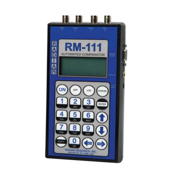
Keypad Conventions Keypad Conventions 3.0 RM-111 Keypad Conventions 1. PORT A Input 2. PORT B Input 3. PORT C Input 4. PORT D Input/Output 5. Serial Port 6. Pickup 7. 9-12V DC Input Jack 8. Cancel 9. Enter 10. Up/Down Arrow Keys 11. - Page 14 Disk Sensor, or the RR-KYZ Pulse Input Adapter 7 9V DC Input: 9-12V DC adapter 8 Cancel: When traversing menus on the RM-111 the CANCEL key performs similar functionality to the ESCAPE key on most software applications. Specifi cally, it should back the user out of the displayed menu leaving any parameters unchanged.
- Page 15 14. The ON key turns the RM-111 power on. The OFF key turns the RM-111 power off. Note that the RM-111 boasts a user confi gurable time out feature and will shut itself off after a pre-set time. However, it will not time out during a test or while in RM-111 Link Mode.
-
Page 16: Menu Structure
The unseen menu items can be viewed by using the RM-111’s DOWN ARROW key to move down the menu. When the user is at the bottom of the menu an UP ARROW icon will appear in the upper right corner of the display. - Page 17 4 Delete All 2 METER TEST 1 View Result 2 Print Result 3 Delete Result 4 Delete All 3 TEST SETUPS 1 STANDARD TEST 1 Edit 2 Create 3 Delete 2 METER TEST 1 Edit 2 Create 3 Delete RM-111 Operations Manual...
- Page 18 3 Result Digits 1 One digit 2 Two Digit 3 Three Digit 4 Kh Format 1 Wh/Pulse 2 Pulses/Wh 5 User Prompts Enter Voltage Enter Test Amps Enter Meter Form Enter Tester ID# Enter Manufacturer ID# Enter Beep RM-111 Operations Manual...
- Page 19 Main Menu Main Menu 6 Time/Date Time: HH:MM:SS Date: MM-DD-YY 7 Power Saver Time in minutes (0-30) 8 About RM-111 S/N: XXXXXX Rev: Vxx.xx.xx 18 18 RM-111 Operations Manual...
-
Page 20: Detailed Description Of Menu Items
View Results - Allows user to view test results. Up to 100 meter and 28 standard test results can be stored and viewed from the RM-111. The LEFT/RIGHT ARROW keys move among the different sets of results. The UP/DOWN ARROW keys move within a single result fi eld to allow all of the result data to be seen. - Page 21 RM-111 Link Mode – Puts the RM-111 in a communication mode, allowing Radian data collection and confi guration software applications to completely take control of the RM-111. The RM-111 must be in this mode to either upload or download test information and results. Results Display – Selects either percent registration or percent error.
- Page 22 Time/Date – View and set the time and date. The time and date are stamped on all results. Power Saver – User can adjust the amount of time before the RM-111 turns off due to inactivity. About – This provides a screen of information specifi c to the RM-111, which includes the device’s serial number and fi...
-
Page 23: Inputs
For testing solid state meters, induction meters or standards the input ports and PICKUP port on the RM-111 are defi ned as DUT inputs. These inputs can be the output of the standard, or in the case of meter testing, any Radian accessory emitting some form of calibration pulse such as the RM-1H, RM-1H/v, RR-1H, RR-DS, RM-DS, or RM-KYZ. - Page 24 With the RM-111’s output defi ned as the RM-1P Electronic Light Valve, applications such as inter- facing with a test board and testing a test board are possible. In this mode the RM-111 produces a continuous pulse train that mimics the hole in the rotating disk of a meter and, therefore, trips the photo pickup.
-
Page 25: Testing A Standard Using The Average Of One To Three Reference Watthour Standards
The *J-44 and *IB-10 can not be tested using pulse counting unless the standards are tested under the Test Meter option of the RM-111 RUN TESTS menu. This is due to the pulses per equivalent revolution of the induction standards. A test of 1000 revolutions would be necessary for one pulse per equivalent revolution if the Test Standard option was used. - Page 26 3. Turn on the RM-111 and select the TEST SETUPS menu option. From the TEST SETUPS menu, select STANDARD TEST. To create a new test setup, select Create. To edit an existing test setup, select Edit.
- Page 27 The “Input A:” parameter input allows the user to select either “REF” or “DUT”. If “REF” is selected, the test will stop after the RM-111 counts the specifi ed number of pulses from the reference standard. If “DUT” is selected, the test will stop after the RM-111 counts the specifi...
- Page 28 14. To print the results connect the RM-RPP Remote Portable Printer to the SERIAL PORT on the RM-111. Turn the RM-RPP to the ON 1 position. Select Print Results. This will start the printing process. The printout is time/date stamped and includes both the watthour count and the calculated % Registration or % Error.
- Page 29 Application 1 Application 1 Figure 3.0 Testing a Radian Standard Using the Average of Three Inputs (Counting Pulses) RM-111 Operations Manual...
- Page 30 Application 1 Application 1 Figure 4.0 Testing a Radian Standard (Counting Pulses) RM-111 Operations Manual...
-
Page 31: True Three Phase Standard Testing
• Auxiliary power can be paralleled on all three of the reference standards. 3. Turn on the RM-111 and select the TEST SETUPS menu option. From the TEST SETUPS menu, select STANDARD TEST. To create a new test setup, select Create. To edit an existing test setup, select Edit. - Page 32 Mode – If more than one reference standard is used, the user must choose between single-phase or polyphase modes of operation. For this application select polyphase. Ref Type – This defi nes the reference standard output pull-up value. Select Radian (150 ohm). Other is 1000 ohm.
- Page 33 The “Input A:” parameter input allows the user to select either “REF” or “DUT”. If “REF” is selected, the test will stop after the RM-111 counts the specifi ed number of pulses from the reference standard. If “DUT” is selected, the test will stop after the RM-111 counts the specifi ed number of pulses from the standard under test.
- Page 34 14. To print the results connect, the RM-RPP Remote Portable Printer to the SERIAL PORT on the RM-111. Turn the RM-RPP to the ON 1 position. Select Print Results. This will start the printing process. The printout is time/date stamped and includes both the watthour count and the calculated % Registration or % Error.
- Page 35 Application 2 Application 2 Figure 5.0 Testing a Polyphase Standard True Three Phase RM-111 Operations Manual...
-
Page 36: Testing A Radian Standard (Display Gating)
3. Turn on the RM-111 and select the TEST SETUPS menu option. From the TEST SETUPS menu, select STANDARD TEST. To create a new test setup, select Create. To edit an existing test setup, select Edit. - Page 37 The “Input A:” parameter input allows the user to select either “REF” or “DUT”. If “REF” is selected, the test will stop after the RM-111 counts the specifi ed number of pulses from the reference standard. If “DUT” is selected, the test will stop after the RM-111 counts the specifi ed number of pulses from the standard under test.
- Page 38 15. To print the results connect the RM-RPP Remote Portable Printer to the SERIAL PORT on the RM-111. Turn the RM-RPP to the ON 1 position. Select Print Results. This will start the printing process. The printout is time/date stamped and includes both the watthour count and the calculated % Registration or % Error.
- Page 39 Application 3 Application 3 Figure 6.0 Testing a Radian Standard (Display Gating) RM-111 Operations Manual...
- Page 40 Application 3 Application 3 Figure 7.0 Testing a Radian Standard Using the Average of Three Inputs (Display Gating) RM-111 Operations Manual...
- Page 41 Example: for the 12.5 amp tap: 100,000 x 1.5 = 150,000. 3. Turn on the RM-111 and select the TEST SETUPS menu option. From the TEST SETUPS menu, select STANDARD TEST. To create a new test setup, select Create. To edit an existing test...
- Page 42 Mode – If more than one reference standard is used, the user must choose between single-phase or polyphase modes of operation. Ref Type – This defi nes the reference standard output pull-up value. Select Radian (150 ohm). Other is 1000 ohm.
-
Page 43: Testing An Electromechanical Standard
The “Input A:” parameter input allows the user to select either “REF” or “DUT”. If “REF” is selected, the test will stop after the RM-111 counts the specifi ed number of pulses from the reference standard. If “DUT” is selected, the test will stop after the RM-111 counts the specifi ed number of pulses from the standard under test. - Page 44 15. To print the results connect the RM-RPP Remote Portable Printer to the SERIAL PORT on the RM-111. Turn the RM-RPP to the ON 1 position. Select Print Results. This will start the printing process. The printout is time/date stamped and includes both the watthour count and the calculated % Registration or % Error.
- Page 45 Application 4 Application 4 Figure 8.0 Testing an Electromechanical Standard (Potential Gating) RM-111 Operations Manual...
-
Page 46: Testing An Electronic Standard With Taps (Potential Gating)
12.5 amp tap: 100,000 x 1.5 = 150,000. 3. Turn on the RM-111 and select the TEST SETUPS menu option. From the TEST SETUPS menu, select STANDARD TEST. To create a new test setup, select Create. To edit an existing test setup, select Edit. - Page 47 Mode – If more than one reference standard is used, the user must choose between single-phase or polyphase modes of operation. Ref Type – This defi nes the reference standard output pull-up value. Select Radian (150 ohm). Other is 1000 ohm.
- Page 48 The “Input A:” parameter input allows the user to select either “REF” or “DUT”. If “REF” is selected, the test will stop after the RM-111 counts the specifi ed number of pulses from the reference standard. If “DUT” is selected, the test will stop after the RM-111 counts the specifi...
- Page 49 15. To print the results connect the RM-RPP Remote Portable Printer to the SERIAL PORT on the RM-111. Turn the RM-RPP to the ON 1 position. Select Print Results. This will start the printing process. The printout is time/date stamped and includes both the watthour count and the calculated % Registration or % Error.
- Page 50 Application 5 Application 5 Figure 9.0 Testing an Electronic Standard (Potential Gating) RM-111 Operations Manual...
-
Page 51: Testing An Electronic Standard (Electronic Gating)
• There are several Electronic Standards that can be tested by electronically gating the display. For testing a SC-10V, A-7 or SC-30, follow the guide for each below, when using a Radian RM or RD series standard as the reference standard. - Page 52 fi t the connectors on the RM-1R or banana plugs. • Maintain the relationship of the RM-1R Electronic relay indicator arrow to the horizon. With the RM-111 laying fl at, the arrow should point up. This is a wetted relay and must stay within 30° of the horizon.
- Page 53 The “Input A:” parameter input allows the user to select either “REF” or “DUT”. If “REF” is selected, the test will stop after the RM-111 counts the specifi ed number of pulses from the reference standard. If “DUT” is selected, the test will stop after the RM-111 counts the specifi ed number of pulses from the standard under test.
- Page 54 15. To print the results connect the RM-RPP Remote Portable Printer to the SERIAL PORT on the RM-111. Turn the RM-RPP to the ON 1 position. Select Print Results. This will start the printing process. The printout is time/date stamped and includes both the watthour count and the calculated % Registration or % Error.
- Page 55 Application 6 Application 6 Figure 10.0 Testing an Electronic Standard (Electronic Gating) RM-111 Operations Manual...
-
Page 56: Testing An Induction Or Solid State Meter Via Kyz
2. Apply test voltage, current and auxiliary power. At this point, both the DUT and the RM or RD reference standard(s) should be running. • Connect all standard pulse outputs to the RM-111. • The RM or RD Primary Reference Watthour Standard will output pulses continuously once auxiliary power, voltage, and current have been applied. - Page 57 1 Rev 12 Pulses 12 Pulses where: Mp = 1/12 = 1 revolution per 12 pulses Kh = 1.8 = watthours per 1 revolution • The formula that the RM-111 uses to calculate percent registration is as follows: RM-111 Operations Manual...
- Page 58 Application 7 Application 7 3. Turn on the RM-111 and select the TEST SETUPS menu option. From the TEST SETUPS menu, select METER TEST. To create a new test setup, select Create. To edit an existing test setup, select Edit. To delete a test, select Delete. The Test Setup screen contains all the necessary parameters to run a meter test.
- Page 59 Mode – If more than one reference standard is used, the user must choose between single-phase or polyphase modes of operation. Ref Type – This defi nes the reference standard output pull-up value. Select Radian (150 ohm). Other is 1000 ohm.
- Page 60 7. Select the previously confi gured test setup. 8. The RM-111 will prompt the user to select either a Manual (RM-1S or RR-1S) test or a Pulse Sensor (RM-KYZ or RR-KYZ) test. Select Pulse Sensor. Select BNC if using an RM-KYZ, or select Lemo if using an RR-KYZ.
- Page 61 16. To print the results connect the RM-RPP Remote Portable Printer to the SERIAL PORT on the RM-111. Turn the RM-RPP to the ON 1 position. Select Print Results. This will start the printing process. The printout is time/date stamped and includes both the watthour count and the calculated % Registration or % Error.
- Page 62 Application 7 Application 7 Figure 11.0 Testing an Induction or Solid State Meter via KYX Output RM-111 Operations Manual...
-
Page 63: Or Induction Meter Using An Edge Test
• To implement a demand and/or creep test to any meter test,set the desired time duration (minutes) in the Test Setup screen. Setting these parameters to zero will omit the test from the sequence. • The formula that the RM-111 uses to calculate percent registration is as follows: RM-111 Operations Manual... - Page 64 Application 8 Application 8 3. Turn on the RM-111 and select the TEST SETUPS menu option. From the TEST SETUPS menu, select METER TEST. To create a new test setup, select Create. To edit an existing test setup, select Edit. To delete a test, select Delete. The Test Setup screen contains all the necessary parameters to run a meter test.
- Page 65 Mode – If more than one reference standard is used, the user must choose between single-phase or polyphase modes of operation. Ref Type – This defi nes the reference standard output pull-up value. Select Radian (150 ohm). Other is 1000 ohm.
- Page 66 7. Select the previously confi gured test setup. 8. The RM-111 will prompt the user to select either a Manual (RM-1S or RR-1S) test or a Pulse Sensor (RM-DS, RR-DS, RM-1H, or RR-1H) test. Select Pulse Sensor. Select BNC if using an RM-1H or RM-DS, or select Lemo if using an RR-1H or RR-DS.
- Page 67 12. In this mode, the RM-111 counts the number of pulses from both the reference standard(s) and the sensor signal from the meter under test. While the test is in progress, the RM-111 display shows the meter registration as it accrues and also shows the the standards counting. When using a pulse sensor, the test automatically stops when the pulse sensor senses the last pulse.
- Page 68 Application 8 Application 8 Figure 12.0 Testing a Solid State Meter Using Calibration LED Output RM-111 Operations Manual...
- Page 69 Application 8 Application 8 Figure 13.0 Testing a Induction Meter Using an Edge Test RM-111 Operations Manual...
-
Page 70: True Three Phase Meter Testing Using Customer Load
(minutes) in the Test Setup screen. Setting these parameters to zero will omit the test from the sequence. 3. Turn on the RM-111 and select the TEST SETUPS menu option. From the TEST SETUPS menu, select METER TEST. To create a new test setup, select Create. To edit an existing test setup, select Edit. - Page 71 Mode – If more than one reference standard is used, the user must choose between single-phase or polyphase modes of operation. For this application, enter polyphase. Ref Type – This defi nes the reference standard output pull-up value. Select Radian (150 ohm). Other is 1000 ohm.
- Page 72 7. Select the previously confi gured test setup. 8. The RM-111 will prompt the user to select either a Manual (RM-1S or RR-1S) test or a Pulse Sensor (RM-DS, RR-DS, RM-1H, or RR-1H) test. Select Pulse Sensor. Select BNC if using an RM-1H or RM-DS, or select Lemo if using an RR-1H or RR-DS.
- Page 73 12. In this mode, the RM-111 counts the number of pulses from both the reference standard(s) and the sensor signal from the meter under test. While the test is in progress, the RM-111 display shows the meter registration as it accrues and also shows the the standards counting. When using a pulse sensor, the test automatically stops when the pulse sensor senses the last pulse.
- Page 74 Application 9 Application 9 Figure 14.0 True Three Phase Meter Testing (Using Customer Load) RM-111 Operations Manual...
- Page 75 6. Select the Pulse Output Type. For this application, select RM-1P. 7. Make the proper connections to the RM-111. Connect the standards to ports A,B, and/or C. Connect the RM-1P to port D. Refer to Figure 16.0 “Testing the Accuracy of a Test Board (RM-1P Electronic Light Valve Option)”...
- Page 76 10. After the test board’s counter has counted the specifi ed number of pulses or disk revolutions it stops the test. 11. The RM-111’s display shows the Kh value entered in the test and the end count of the standard(s). The test board itself shows the percent error, which is the percent error of the test board.
- Page 77 Application 10 Application 10 Figure 15.0 Testing the Accuracy of a Test Board (RM-1P Light Valve Option) RM-111 Operations Manual...
- Page 78 6. Make the proper connections to the RM-111. Connect the standard(s) to ports A,B, and/or C. Connect the test board to port D. Refer to Figure 17.0 “Testing the Accuracy of a Test Board (Open Collector Option)”...
- Page 79 9. The RM-111’s display shows the Kh value entered earlier in the test and the end count of the standard(s). The test board itself shows the percent error, which is the percent error of the test board.
- Page 80 Application 11 Application 11 Figure 16.0 Testing the Accuracy of a Test Board (Open Collector Option) RM-111 Operations Manual...
- Page 81 5. Enter the number of pulse input ports (1-3). 6. Select the pulse output type. For this application, choose Open Collector. 7. Make proper connections to the RM-111, see fi gure 18.0. Connect Pulse IN(s) to port(s) A, B, and/or D and Pulse OUT to port D.
- Page 82 Application 12 CANCEL key is pressed. 10. The RM-111’s display shows the pulses IN per the pulses OUT for as long as the test is ran. For this application, there are no results and therefore no save option. RM-111 Operations Manual...
- Page 83 Application 12 Application 12 Figure 17.0 Interfacing a Solid State Meter to a Test Board (Open Collector Option) RM-111 Operations Manual...
- Page 84 1. Install the meter to be tested into the test board socket fi xture. 2. Position the RM-1P between the test board’s light emitter and detector. • The RM-1P will function with both visible and infrared light. 3. Turn on the RM-111. 4. Select RUN TESTS. 5. Select Pulse Divider.
- Page 85 RM-111 outputs one pulse. This continues until the RM-111’s CANCEL key is pressed. 12. The RM-111’s display shows the pulses IN per the pulses OUT for as long as the test is ran. For this application there are no results and therefore no save option.
- Page 86 Application 10 Application 10 Application 13 Application 13 Figure 18.0 Interfacing a Solid State Meter to a Test Board (RM-1P Electronic Light Valve Option) RM-111 Operations Manual...
-
Page 87: Pulse Constants And Kh Values For The Rm-111
Pulse Constants Pulse Constants 20.0 Pulse Constants and Kh values for the RM-111 (*SC-10, *SC-10v, *SC-30, *A-7, *IB-10 and the RM-16) Note: When using an RM-16 the position of the Pulse Constant switch located on the front panel, will be the multiplier for the following pulse constants and Kh values. The chart below is applicable for the 1,000 switch setting. -
Page 88: Calculations
Calculations 21.0 CALCULATIONS The following are calculations used for percent registration by the RM-111. For percent error, just take the percent registration minus 100%. For example, if percent registration is 99%, then percent error is 99% - 100% = -1.0%. Note that the negative percent error indicates that the meter is running slow. - Page 89 2-phase, then 2 reference standards must be connected to ports B and C, B and D or C and D. If two or three current inputs on the reference standards are connected in series, then the reference pulse constant must be adjusted by the number of current inputs in series. See NOTE#1 for standard testing. RM-111 Operations Manual...
- Page 90 The RM-1H Infrared Optical Pickup is used to sense the infrared pulses from the calibration LED of solid state meters. The pulses from the RM-1H are fed into the input of the RM-111 into port A. When the RM-1H is used with the RM-111 Automated Comparator the testing of solid state meters is done automatically.
- Page 91 The RR-1H Infrared Optical Pickup is used to sense the infrared pulses from the calibration LED of solid state meters. The pulses from the RR-1H are fed into the input of the RM-111 into the Pickup port. When the RR-1H is used with the RM-111 Automated Comparator the testing of solid state meters is done automatically.
- Page 92 The RM-KYZ Pulse Input Adapter is used to sense the KYZ output pulses of an induction type or solid state meters. The pulses received from the meter’s KYZ output are conditioned and fed into input port A of the RM-111 Automated Comparator. With the RM-KYZ and the RM-111 the testing of KYZ equipped meters is done automatically.
- Page 93 The pulses generated by the RM-DS are fed into input port A of the RM- 111 Automated Comparator. With the RM-DS and the RM-111 testing of induction type meters is done automatically and with a high degree of accuracy compared to using a conventional push button or snap switch.
- Page 94 Test Accessories Test Accessories The RM-1P Electronic Light Valve is used to interface the output of the RM-111 Automated Comparator with the optics of a calibration test board. The RM-1P operates with both incandescent and infrared optic assemblies. To trigger incandescent source optics, the RM-1P uses a super luminous LED.
- Page 95 Test Accessories Test Accessories The RM-RPP Remote Portable Printer is used for printing results from the RM-111 Automated Comparator. The RM-RPP has an abundance of benefi cial features in one of the smallest, lightest printer packages available. Offering features such as bi-directional printing, logic-seeking print and a variety of character formats including condensed and enhanced print fonts.
- Page 96 The RM-1R Electronic/Mechanical Potential Relay houses two independent relays necessary for the electronic and mechanical Potential gating options supported by the RM-111. The relay used is determined by the RM-1R BNC connection used. The electronic relay is a mercury wetted reed relay used for testing *SC-10's, *SC-10/r's and *A-7's..
-
Page 97: Warranty Service
3852 Fortune Drive Lafayette, IN 47905 USA Attn: RM-111 Service The RM-111 is 100% digital and will remain within 0.0001% transfer error for life. It never needs to be calibrated. SC-10, SC-30, and SC-60 are trademarks of the Scientifi c Columbus Company.
Need help?
Do you have a question about the RM-111 and is the answer not in the manual?
Questions and answers