
Related Manuals for Mirion Technologies CheckPoint:Laundry RTM750


Summary of Contents for Mirion Technologies CheckPoint:Laundry RTM750
- Page 1 User Manual Laundry measurement station CheckPoint:Laundry™ RTM750 Juni 2016 TD750Exx000R01...
- Page 2 Responsible Modification Approved by TD750Exx000R01 2016-Jun-13 Dorett First Release Dirk Marks Schäftner All rights reserved at: Mirion Technologies (RADOS) GmbH D-22761 Hamburg (Germany) Ruhrstraße 49 Tel.: +49-40-85193-0 Fax: +49-40-85193-256 E-Mail: hamburg-info@mirion.com Mirion Hotline: +49-40-85193-222 E-Mail: hamburg-hotline@mirion.com Printed in Germany TD750Exx000R01...
-
Page 3: Table Of Contents
RTM750 Table of contents Table of contents 1 Introduction ......................1 Liability ...........................1 Identification Plate ...........................1 Standards ...........................1 Copyright ...........................2 Supplier Documentation ...........................2 Spare Parts ...........................2 Layout of Safety Messages ...........................2 Additional Information ...........................2 List of Abbreviations ...........................3 2 Safety ......................5 Intended Use ...........................5 Personnel Requirements... - Page 4 RTM750 Table of contents 4.4.4 Keyboard .......................18 5 Commissioning ......................19 Transport and Unpacking ...........................19 5.1.1 Shipping Items .......................20 5.1.2 Delivery Confirmation .......................20 5.1.3 Temporary Storage .......................20 5.1.4 Unpacking .......................20 5.1.5 Damage Claim .......................20 5.1.6 Recycling of Packing Material .......................20 5.1.7 Transport to Installation Location .......................20 Assembly and Configuration...
- Page 5 RTM750 Table of contents Definition of Relevant Parameters ...........................38 7.5.1 User Administration .......................38 7.5.2 Background Parameters .......................39 7.5.3 Test Source .......................39 7.5.4 Average Area .......................40 7.5.5 Parameterset .......................40 7.5.6 Processes (for System Checks/Calibrations) .......................42 7.5.7 High Voltage .......................43 7.5.8 On-screen Gas Alerts .......................43 Miscellaneous Settings ...........................44...
- Page 6 RTM750 Table of contents 9.4.3 Replacement of the Anode Wire .......................61 9.4.4 Detector Address Assignment .......................62 9.4.5 Calibration .......................62 System Checks ...........................63 Optical Sensor(s) ...........................66 9.6.1 Replacement .......................66 Push Buttons: Start/Stop and Emergency Stop ...........................68 Conveyor ...........................69 9.8.1 Conveyor Belt Adjustment .......................69 9.8.2 Belt Drive Adjustment...
- Page 7 RTM750 Table of contents 13.06.2016 TD750Exx000R01...
-
Page 8: Introduction
Introduction RTM750 Introduction Liability Liability for personal injury and property damage is excluded, if they can be traced to one or more of the following causes: · Non-observance of the user manual. · Non-observance of safety precautions and safety messages. ·... -
Page 9: Copyright
No part of this manual may be copied, duplicated in any respect, given or made accessible to a third party without obtaining the express permission of Mirion Technologies (RADOS) GmbH. -
Page 10: List Of Abbreviations
Introduction RTM750 Additional Information List of Abbreviations Abbreviation Description Argon bckgrd background Becquerel CeMoSys Central Monitoring System Methane counts per second database Direct Current dual in-line package e.g. for example EEPROM Electrically Erasable Programmable Read-Only Memory Hertz kilogram Liquid Crystal Display Light Emitting Diode maximum mbar... - Page 11 RTM750 Introduction List of Abbreviations 13.06.2016 TD750Exx000R01...
-
Page 12: Safety
Safety RTM750 Safety The following chapters give detailed information on safety-relevant topics such as the intended use of the monitor, relevant safety messages and warning signs on the monitor. Furthermore, the personal protective equipment and personnel requirements are specified. Intended Use NOTICE Improper use can cause damages. -
Page 13: Personal Protective Equipment
RTM750 Safety Personnel Requirements Personal Protective Equipment During the operation, cleaning or maintenance, wear suitable protective clothing. For details, refer to the instructions in the manual. The following protective equipment must be provided: Symbol Designation Safety gloves Safety footwear, according to DIN EN ISO 20345, category S3, or in compliance with local regulations. -
Page 14: Safety Installations
Safety RTM750 Warning Signs and Instructions on the Monitor Safety Installations The machine has the following safety installations/features: · Emergency stop push buttons. Before you start the operation of the monitor, make sure that all safety installations are present and operational. 2.5.1 Emergency Stop Location... -
Page 15: Operational Safety
RTM750 Safety Electrical Safety Obey these safety requirements before and during the operation of the monitor: 1. Make sure that you: · Only use the power cords and cables that are supplied with this equipment. · Do not use extension cords. ·... -
Page 16: Technical Data
Technical Data RTM750 Technical Data Ambient Operation Transport and Storage Conditions Ambient temperature +5°C to +45°C -20°C to +55°C Atmospheric moisture 85% annual average or 95% for a max. of 5h, 85% annual average or 95% for a max. of non-condensing 5h, non-condensing Dimensions... -
Page 17: Minimum Detectable Activity (Mda)
RTM750 Technical Data Minimum Detectable Activity (MDA) The Minimum Detectable Activity, or MDA, represents the smallest quantity of a radioisotope which can be detected. Parameter Setting Sigma 1.65 + 1.65 Background 0.1 µ Sv/h Belt Speed 1.2 m/min Source RGZ730Y Alpha [Bq] RGZ730Y Beta [Bq] Co-60 C-14... -
Page 18: Product Description
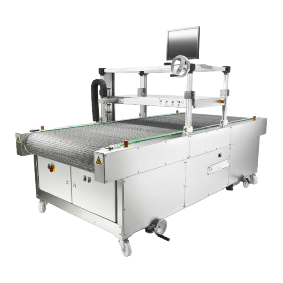
Product Description RTM750 Product Description The following chapters give an overview of the monitor and its components. The location of each component is shown and a detailed description of their function given. General The RTM750 laundry monitor is used in places where the surface contamination on clothing or on small objects such as tools has to be monitored. -
Page 19: Electrical Cabinet
RTM750 Product Description General Electrical Cabinet The electrical cabinet holds the major electrical components to protect them from the environment and to prevent electrical shock to equipment users. Refer to the applicable schematic(s) for all relevant details such as power supply and distribution, electrical wiring or the component location, if applicable. -
Page 20: Frequency Converter
Product Description RTM750 Electrical Cabinet GND VCC DC power SIM Card COM2 COM1 Gas supply unit Display USB (2x) 1 x Touch display; 1 x n/a LAN2 CeMoSys (if applicable) LAN1 4.2.2 Frequency Converter A frequency converter is an electronic device that converts alternating current (AC) of one frequency to alternating current of another frequency. -
Page 21: Detection Equipment
RTM750 Product Description Electrical Cabinet Detection Equipment The following chapters describe the main components for the detection of ionizing radiation. 4.3.1 Gas Supply Unit with Digital Gas Flow Meter The medium used to detect ionizing radiation is a gas mixture, which constantly flows at a set pressure through all detectors and fills them. - Page 22 Product Description RTM750 Detection Equipment If the symbol for the gas pressure is: · green, the gas pressure is OK · red, the gas pressure is not OK and a related warning is shown. When the gas pressure becomes normal again, the monitor becomes “Ready to Measure”, the related warning goes off and the gas pressure symbol becomes green.
-
Page 23: Detectors
RTM750 Product Description Detection Equipment 4.3.2 Detectors The gas-flow proportional detectors can detect and optionally discriminate α and β radiation. The detector housing has a very stable design. A detector foil placed between the housing and the screw-on cover is an airtight barrier. It allows the radiation to enter but keeps the gas firmly inside the detector. -
Page 24: Optical Sensors
Product Description RTM750 Detection Equipment 4.3.3 Optical Sensors The monitor is equipped with a variety of sensors which have different functions. All of them send their signals to the RLC. Start of belt movement A set of optical sensors is installed on top of the monitor at the loading side. These senors have a sender unit and a receiver unit. -
Page 25: Keyboard
RTM750 Product Description Human Machine Interface 4.4.4 Keyboard In addition to the input via touchscreen it is possible to use a keyboard . It connects to an external USB port. A keyboard is required for any settings in the system configuration. 13.06.2016 TD750Exx000R01... -
Page 26: Commissioning
Commissioning RTM750 Commissioning Tools (as required): · Forklift · Crane · Tension belt · Screwdriver TX20 It is required that the commissioning is done by qualified personnel only. It is required that the personnel responsible for the commissioning: · Wear the personal protective equipment as described in chapter 2.3. ·... -
Page 27: Shipping Items
RTM750 Commissioning Transport and Unpacking 5.1.1 Shipping Items The monitor, the required equipment and the documentation are shipped in a wooden box. 5.1.2 Delivery Confirmation Make sure that the shipment is complete and in accordance with the packing slip. If the shipment is complete, confirm the packing slip (signature). Do not confirm the packing slip, if the shipment is incomplete. -
Page 28: Assembly And Configuration
Commissioning RTM750 Transport and Unpacking Assembly and Configuration NOTICE Improper use can falsify measurement results. Risk of incorrect measurement results. The detectors are adjusted with the gas mixture specified in chapter 3. The use of other gases prevents the correct operation of the detectors. NOTE Refer to the applicable maintenance chapters for the required tools and safety instructions. - Page 29 RTM750 Commissioning Assembly and Configuration 7.5.4). d. Do the calibration(s) (refer to chapter 9.4.5). 5. After the creation/definition of all relevant parameters do a backup of these parameters (refer to chapter 7.2.1). 6. Do a function check of the emergency stop push buttons (refer to chapter 2.5.1). 13.06.2016 TD750Exx000R01...
-
Page 30: Transport To Another Installation Location
Commissioning RTM750 Assembly and Configuration Transport to another Installation Location WARNING Risk of crushing due to heavy loads. Risk of severe injuries. – Use adequate and certified means of transport. – Make sure that you wear safety shoes and safety gloves. –... -
Page 31: Decommissioning And Disassembly
RTM750 Commissioning Decommissioning and Disassembly Decommissioning and Disassembly DANGER Danger due to electric components that are still energized when the main switch is set to OFF. Risk of electric shock! – Make sure that these components are clearly identified at all times. –... -
Page 32: Control And Operation
Control and Operation RTM750 Control and Operation The following chapters explain the operation of the monitor and give an overview of the main control elements. Furthermore, the correct start and shutdown procedures are explained. Mechanical and Graphical Control Elements The main operation controls are listed in the table below. Designation Color Function... -
Page 33: Operation Modes
RTM750 Control and Operation Mechanical and Graphical Control Elements Print Press to print the active screen. Previous Screen Press to go to the previous screen. Next Screen Press to go to the next screen. Save Press to save a new entry or changes to existing entries (starts flashing red when values or parameters changed). -
Page 34: Background Measurement
Control and Operation RTM750 System Start Background Measurement NOTE The background measurement is a continuous process, which starts or continues when all requirements are fulfilled. We recommend to manually discard the background and start a new background measurement, when the requirements cannot be fulfilled during long measurement periods or due to constant interruptions. - Page 35 RTM750 Control and Operation Contamination Measurement left and right side of the screen there is an arrow icon. These icons have the function to switch between screens. Each screen shows one of the available parametersets and all relevant information such as the conveyor speed or the unit. A contamination measurement can start: ·...
-
Page 36: Authorization Levels (User Administration)
Control and Operation RTM750 Contamination Measurement Measurement Mode - Ready to Measure If any changes of the measurement parameters are required, it is necessary to enter the maintenance menu with a tap on the button MAINTENANCE on the bottom of the display and the applicable authorization level. -
Page 37: Shutdown Of The Computer
Ethernet. The system consists of a central database server and any number of clients. More than 100 Mirion Technologies (RADOS) GmbH devices can be monitored at the same time from any PC within the network. CeMoSys™ provides an overview of measurement results and system information. - Page 38 Control and Operation RTM750 CeMoSys case of contamination or a status change, the registered users (clients) are informed automatically. If a monitor is connected to CeMoSys™, the related icon shows in the top right corner of the display. CeMoSys - Status icons TD750Exx000R01 13.06.2016...
-
Page 39: Software
RTM750 Software Software The software and all related parameters are preinstalled at delivery. This chapter gives instructions for all parameter settings. Graphical Control Elements Text box A text box allows text and data input via onscreen keyboard. Tap to open the edit mode. Onscreen keyboard The onscreen keyboard allows the input of alphanumeric characters. - Page 40 Software RTM750 Graphical Control Elements Button A button allows the user to trigger an event such as the confirmation of an action or the interaction with dialog boxes. Active button Inactive button (function not available) Dialog box A dialog box gives information to the user and requires an action. Progress bar A progress bar visualizes the progression of an operation or a process.
-
Page 41: Backup
RTM750 Software Graphical Control Elements Backup 7.2.1 Parameter Export NOTICE We recommend that you always do a parameter export when you change an important parameter to prevent a loss of data. In the maintenance menu, go to Miscellaneous > Save Parameters. 1. -
Page 42: Start Menu
Software RTM750 System Configuration 7.3.1 Start Menu To get access to the functions of the start menu, it is necessary to: 1. Log in the maintenance mode as Superuser. 2. Press EXIT USER SOFTWARE. 3. Confirm the dialog. 7.3.2 Touchscreen Calibration 1. -
Page 43: Network Configuration
RTM750 Software System Configuration a. Press SELECT ANOTHER MAKE/MANUFACTURER and select "Generic". Press CONTINUE. b. Select "Generic PostScript Level 1 Printer [...]" from the list and press ADD PRINTER. 9. Define the general settings such as the page size. 10. Do the setup as required, then close the printer configuration dialog. Delete a Printer 1. - Page 44 Software RTM750 System Configuration 4. If necessary, enter the custom licence key and press NEXT. 5. Open the combo box and select the applicable hardware from the list. Press APPLY for confirmation. 6. Enter all geometry data and press NEXT. 7.
-
Page 45: The Maintenance Menu
RTM750 Software System Configuration The Maintenance Menu All relevant parameters are defined and can be changed in the maintenance menu. Architecture of the maintenance menu Maintenance Status Inputs/Outputs Channel Status Hardware Channel Configuration Measurement Errors System Check Gas Flowmeter Parameters & Calibration Background Measurement General Measurement Options... -
Page 46: Background Parameters
Software RTM750 Definition of Relevant Parameters NOTE: The icon frame becomes blue. 2. Tap on the related textboxes to change the username and the password. Then verify your password. Confirm the entries with APPLY. 3. If necessary, select the required group and icon from the related combo boxes. Confirm the selections with APPLY. -
Page 47: Average Area
RTM750 Software Definition of Relevant Parameters 3. Press the button to access the nuclide DB. 4. Tap on the required nuclide and press SELECT. NOTE: When a nuclide is selected, the additional information about its half-life in years and the related radiation types are shown. 5. - Page 48 Software RTM750 Definition of Relevant Parameters a. Press CALCULATION PARAMETERS. b. Define the false alarm and the detection safety. 5. Select the measurement unit: a. Press UNIT / LEVELS. b. Press ALPHA. c. Open the related combo box and select the measurement unit. NOTE: The units cps and cpm do not require a calibration.
-
Page 49: Processes (For System Checks/Calibrations)
RTM750 Software Definition of Relevant Parameters 7.5.6 Processes (for System Checks/Calibrations) NOTE The test templates for system checks or calibrations are called processes. Each process requires a test source (refer to chapter 7.5.3). In the maintenance menu, go to Databases > Processes to create test templates. Add a process: 1. -
Page 50: High Voltage
Software RTM750 Definition of Relevant Parameters 7.5.7 High Voltage NOTE For the required High Voltage (HV), refer to chapter 3. NOTE A change of the HV always affects the calibration and invalidates existing calibration results. If necessary, set the HV: 1. -
Page 51: Miscellaneous Settings
RTM750 Software Definition of Relevant Parameters Miscellaneous Settings 7.6.1 Measurement Results - Storage Settings In the maintenance menu, go to Parameters & Calibration > Results. Decide, which type of measurement results are stored in the database. Check the applicable checkbox: ·... -
Page 52: Timer Settings
Software RTM750 Miscellaneous Settings NOTE: The new mean value and its standard deviation are shown in the list. 7.6.6 Timer Settings In the maintenance menu, go to Parameters & Calibration > Process Control. NOTE: The value 0 seconds suppresses the related function. For Measurement Results 1. -
Page 53: Channel Status
RTM750 Software Retrieval of Information 7.7.3 Channel Status In the maintenance menu, go to Status > Channel Status. The list gives specific values and calculations for each channel and each sum channel: Value Description Rate [cps] Current count rate per second mean [cps] Calculated mean value σ... -
Page 54: Information/Error List
Software RTM750 Retrieval of Information · The Severity. An error causes the monitor to stop the operation. The monitor is “Not Ready to Measure”. 7.7.6 Information/Error List In the maintenance menu, go to Miscellaneous > Information/Error List. The function lists all relevant information about the user software. - Page 55 RTM750 Software Retrieval of Information a. Tap on the applicable check box(es) and select the required date(s). b. Tap on the related check box to show only results with or without contamination. 3. Then press BACK to return to the list. To see the details of a result, tap on a result in the list, then press SHOW DETAILS.
- Page 56 Software RTM750 Retrieval of Information Measurement Result - Detail View Color Codes Description White No contamination Contamination Pink High contamination System Check/Calibration Results In the maintenance menu, go to Databases > System Check/ Calibration Results. The list shows all completed system checks and calibrations. Each result has these identifiers: ·...
-
Page 57: Print Options
RTM750 Software Retrieval of Information 7.7.11 Print Options It is possible to make hard copies or create and store PDFs of: · Parameters · Measurement results · System check or calibration results. 1. In the maintenance menu, go to: · Miscellaneous > Print all Parameters to print all parameters ·... - Page 58 Software RTM750 Retrieval of Information TD750Exx000R01 13.06.2016...
-
Page 59: Description Of Parameters & Functions
RTM750 Description of Parameters & Functions Description of Parameters & Functions Status Channel Status Calculate mean It is possible to do a mean calculation for each detector/ channel. The defined time is the basis for the calculation of the mean. Parameters &... -
Page 60: Databases
Description of Parameters & Functions RTM750 Databases Databases Measurement Results Date Shows the date of the measurement. Time Shows the time of the measurement. Result Shows if the measurement has a contamination above clearance level or no contamination. Nuclides Atomic number The atomic number is the number of protons found in the nucleus of the atom. - Page 61 RTM750 Description of Parameters & Functions Databases determination, i.e. the position of the same test source must be at the same position. Background measuring time Each system check requires a new background. The background measuring time defined the required duration for the determination of the background.
-
Page 62: Maintenance
Maintenance RTM750 Maintenance The following chapters explain in detail the replacement and/or the adjustment of components. Each chapter starts with a list of all required tools and preliminary work steps (job set-up) for the related tasks. Get Access Tools: · Socket wrench – 7 mm (M4) ·... -
Page 63: Display Holder
RTM750 Maintenance Get Access Access doors D1 thru D3 1. Open: a. Use: - A double bit key to unlock and open the access doors D1 and D2. - A square socket key to unlock and open the access door D3. 2. -
Page 64: Display
Maintenance RTM750 Display Holder Display 9.3.1 Replacement and Adjustment NOTE The adjustment of display attributes such as brightness or contrast is only possible when the display housing is disassembled. The related control buttons are located at the rear of the display. Tools: ·... -
Page 65: Detectors
RTM750 Maintenance Detectors Detectors 9.4.1 Replacement of a Detector Tools: · Socket wrench – 7 mm (M4) · Bypass hose(s) Job Set-up: · Switch off the computer (refer to chapter 6.7). · Set the main switch to OFF. · Get access to the related detector(s) (refer to chapter 9.1). Bottom detector Removal: 1. - Page 66 Maintenance RTM750 Detectors 2. At the detector: a. Disconnect the data cables from the Ethernet ports (5) and the electrical connectors (6). b. At the gas inlet/outlet (3), push the blue ring (7) while you remove the gas hose. 3. Install a temporary bypass hose. Installation: 1.
-
Page 67: Replacement Of The Detector Foil (Mylar)
RTM750 Maintenance Detectors 9.4.2 Replacement of the Detector Foil (Mylar) NOTE Mylar can be obtained from Mirion. Tools: · Mylar - 6 µm · Scalpel Job Set-up: · Remove the detector (refer to chapter 9.4.1). Replacement: 1. Remove the screws (3) and the cover (1). 2. -
Page 68: Replacement Of The Anode Wire
Maintenance RTM750 Detectors 9.4.3 Replacement of the Anode Wire WARNING Risk of sharp, flying objects due to use of pressurized air. Risk of severe injuries to the eyes! – Wear safety glasses when you use pressurized air for cleaning. Tools: ·... -
Page 69: Detector Address Assignment
RTM750 Maintenance Detectors 9.4.4 Detector Address Assignment NOTE Each replacement of a detector requires a detector address configuration. 1. At the bottom of the related detector, get access to the DIP switches. 2. Refer to the schematic diagram "detector cables" for the position of the detectors. 3. -
Page 70: System Checks
Maintenance RTM750 Detectors 6. Make sure that all requirements for a background measurement are fulfilled, then press START BACKGROUND. 7. When the progress bar shows 100%: a. Do a check of the background values in the list, if necessary. b. Press NEXT. NOTE: The screen “Calibration:Measurement”... - Page 71 RTM750 Maintenance System Checks ii. Press START MEASUREMENT. iii. When the progress bar shows 100%, repeat steps i and ii. b. For a check of single detectors: i. Press NEXT CHANNEL until the applicable detector shows a black frame. ii. Put the test source in position on the applicable detector. iii.
- Page 72 Maintenance RTM750 System Checks 7. Press NEXT. 8. Define a name for test and press SAVE. TD750Exx000R01 13.06.2016...
-
Page 73: Optical Sensor(S)
RTM750 Maintenance System Checks Optical Sensor(s) 9.6.1 Replacement NOTICE Improper use can cause short circuits. Risk of property damage! – Before you do maintenance work, disconnect the monitor from the main power supply and ensure that all connected wires have zero-potential. Tools: ·... - Page 74 Maintenance RTM750 Optical Sensor(s) 6. Make sure that the new optical sensor operates correctly. Replacement of an optical sensor TD750Exx000R01 13.06.2016...
-
Page 75: Push Buttons: Start/Stop And Emergency Stop
RTM750 Maintenance Optical Sensor(s) Push Buttons: Start/Stop and Emergency Stop NOTE Information extracted from the EATON document 02/15 IL04716002Z (AWA1160-1745, IL04716001E). Tools: · Screwdriver, slot-head - size 2 Job Set-up: · Switch off the computer (refer to chapter 6.7). · Set the main switch to OFF. ·... -
Page 76: Conveyor
Maintenance RTM750 Conveyor Conveyor 9.8.1 Conveyor Belt Adjustment NOTE There are three adjustment bolts on the monitor. All of them can correct misalignments of the deflection rollers. In addition, the adjustment bolts on the loading side are also used to adjust the tension of the conveyor belt. - Page 77 RTM750 Maintenance Conveyor Conveyor belt adjustment 13.06.2016 TD750Exx000R01...
-
Page 78: Belt Drive Adjustment
Maintenance RTM750 Conveyor 9.8.2 Belt Drive Adjustment NOTE When the motor is lifted or lowered, the tension of the driving chain changes. Tools: · Open-end wrench (impact wrench, if necessary) – M8 Job Set-up: · Switch off the computer (refer to chapter 6.7). ·... -
Page 79: Computer
RTM750 Maintenance Conveyor Computer Tools: · Socket wrench – M3 Job Set-up: · Switch off the computer (refer to chapter 6.7). · Set the main switch to OFF. · Get access to the computer (refer to chapter 9.1). · Disconnect all connectors. Removal: 1. -
Page 80: Computer Battery
Maintenance RTM750 Data Storage Device 9.11 Computer Battery NOTE The removal of the computer battery resets all BIOS parameters to the default values. A battery replacement requires a new BIOS parameter configuration. Before you remove the battery, make a screenshot of all required BIOS settings. Tools: ·... -
Page 81: Maintenance Plan
RTM750 Maintenance Plan Maintenance Plan NOTE We recommend regular maintenance checks. Refer to the list below and to the applicable sections in the related test report. Maintenance intervals Designation Maintenance tasks every 6 weekly monthly annually other months Gas supply Check all gas connections. - Page 82 Maintenance Plan RTM750 TD750Exx000R01 13.06.2016...
-
Page 83: Troubleshooting
RTM750 Troubleshooting Troubleshooting For the analysis of errors, refer as applicable to: · the Error Status (Maintenance menu > Status > Errors) · the Hardware Status (Maintenance menu > Status > Hardware) · the channel status Maintenance menu > Status > Channel Status) ·... - Page 84 Troubleshooting RTM750 Measurement time calculation The measurement time Wait until the progress is completed. in progress, please wait calculation requires more time ERROR_MEAS_TIME_CALCULATI than usual ON_IN_PROGRESS Background error Invalid background parameters Check the parameters for the background ERROR_BACKGROUND_ERROR measurement (refer to chapter 7.5.2). Background too high Background is above Maximum Check and if necessary, correct the value for...
-
Page 85: Basic Principles And Methods
RTM750 Basic Principles and Methods Basic Principles and Methods 12.1 Background 12.1.1 General Meaning of Background Background radiation is the ionizing radiation that people on the planet are exposed to, including natural and artificial sources. The natural sources can be of terrestrial or cosmic origin. -
Page 86: Efficiency Calculation
Basic Principles and Methods RTM750 Measurement Method whereby background measurement time, expectation value of the background, expectation value of the net measurement effect, Quantile error type I (false alarm), 1-α Quantile error type II (detection safety). 1-β The automatic measurement time can be limited by the selection of a shortest and a longest measurement time. -
Page 87: Calculated Alarm Level
RTM750 Basic Principles and Methods Measurement Method Gross rate Background rate Efficiency (if the result is cps, the efficiency is 1) 12.2.4 Calculated Alarm Level The set alarm level is rated with a statistical safety to ensure the detection safety. The following equation shows the calculation of the actual alarm: with actual alarm threshold... -
Page 88: Units
Basic Principles and Methods RTM750 Measurement Method 12.2.7 Units The software is able to present the measurement result in the physical units counts per second (cps), Becquerel (Bq), decays per minute (dpm) and Nanocurie (nCi). Except for cps a calibration and therefore its factor is required to calculate the respective value in the unit selected. -
Page 89: Moving Average
RTM750 Basic Principles and Methods Mathematical and Physical Principles Probability Quantile Quantile Quantile Detection Confidence against false k 1-α k 1-ß k 1-g/2 Safety Level alarm 68 % 16 % 68 % 95 % 1.65 s 1.65 s 1.65 s 98 % 96 % 2.05 s... - Page 90 Basic Principles and Methods RTM750 Mathematical and Physical Principles TD750Exx000R01 13.06.2016...
-
Page 91: Appendix/Appendices
RTM750 Appendix/Appendices Appendix/Appendices · Declaration of Conformity · Schematic Diagrams · Test Procedure/Report · User Software (USB flash drive) · Supplier documents. 13.06.2016 TD750Exx000R01... - Page 92 Appendix/Appendices RTM750 TD750Exx000R01 13.06.2016...
Need help?
Do you have a question about the CheckPoint:Laundry RTM750 and is the answer not in the manual?
Questions and answers