Table of Contents
Advertisement
Quick Links
Advertisement
Table of Contents

Related Manuals for Goulds Pumps VIT


Summary of Contents for Goulds Pumps VIT
- Page 1 Installation, Operation, and Maintenance Manual Model VIT, VIC and VIDS...
-
Page 3: Table Of Contents
4.4.8 Installing the enclosing tube tension plate ..................48 4.4.9 Installing a solid-shaft driver......................51 4.4.10 Installing a hollow-shaft driver..................... 54 4.4.11 Set up the lubrication system ...................... 59 4.4.12 Flush water system setup ......................60 Model VIT, VIC and VIDS Installation, Operation, and Maintenance Manual... - Page 4 9.1 Example of VIC-L barrel installation ......................96 10 Annex II ................................ 101 10.1 Tightening torque tables ........................101 11 CE Declaration of Conformity........................105 11.1 CE Declaration of Conformity ......................105 Model VIT, VIC and VIDS Installation, Operation, and Maintenance Manual...
- Page 5 Table of Contents 12 Local ITT Contacts ............................107 12.1 Regional offices........................... 107 Model VIT, VIC and VIDS Installation, Operation, and Maintenance Manual...
-
Page 6: Introduction And Safety
ITT. If there is any uncertainty regarding the appropriate use of the equipment, please contact an ITT representative before proceeding. Model VIT, VIC and VIDS Installation, Operation, and Maintenance Manual... -
Page 7: Safety Terminology And Symbols
A hazardous situation which, if not avoided, will result in death or seri- ous injury WARNING: A hazardous situation which, if not avoided, could result in death or serious injury Model VIT, VIC and VIDS Installation, Operation, and Maintenance Manual... -
Page 8: Environmental Safety
Handle and dispose of the processed liquid in compliance with applicable environmental regula- tions. • Clean up all spills in accordance with safety and environmental procedures. • Report all environmental emissions to the appropriate authorities. Model VIT, VIC and VIDS Installation, Operation, and Maintenance Manual... -
Page 9: User Safety
Consider limiting personnel’s exposure time to noise or, where possible, en- closing equipment to reduce noise. Local law may provide specific guidance regarding expo- sure of personnel to noise and when noise exposure reduction is required. Model VIT, VIC and VIDS Installation, Operation, and Maintenance Manual... - Page 10 Beware of the starting jerk, which can be powerful. • Rinse the components in water after you disassemble the pump. • Do not exceed the maximum working pressure of the pump. Model VIT, VIC and VIDS Installation, Operation, and Maintenance Manual...
-
Page 11: Ex-Approved Products
• Any maintenance for Ex-approved products must conform to international and national standards. ITT disclaims all responsibility for work done by untrained and unauthorized personnel. Model VIT, VIC and VIDS Installation, Operation, and Maintenance Manual... -
Page 12: Noise Level Data
• Modifications or changes to the product and installation made without consulting ITT • Incorrectly executed repair work • Normal wear and tear ITT assumes no liability for these situations: Model VIT, VIC and VIDS Installation, Operation, and Maintenance Manual... -
Page 13: Atex Considerations And Intended Use
Maintenance manual (IOM) can cause serious personal injury or damage to the equipment. This in- cludes any modification to the equipment or use of parts not provided by ITT Goulds Pumps. If there is any question regarding the intended use of the equipment, please contact an ITT Goulds representative before proceeding. - Page 14 The code classification marked on the equipment must be in accordance with the specified area where the equipment will be installed. If it is not, do not operate the equipment and contact your ITT Goulds Pumps sales representative before proceeding. Model VIT, VIC and VIDS Installation, Operation, and Maintenance Manual...
-
Page 15: Transportation And Storage
Lifting and handling heavy equipment poses a crush hazard. Use caution during lifting and handling and wear appropriate Personal Protective Equipment (PPE, such as steel- toed shoes, gloves, etc.) at all times. Seek assistance if necessary. Model VIT, VIC and VIDS Installation, Operation, and Maintenance Manual... - Page 16 Lifting lugs on head maybe used once pump has been removed off shipping skid. Example: VIT lifted from horizontal to vertical Figure 2: VIT horizontal position Model VIT, VIC and VIDS Installation, Operation, and Maintenance Manual...
- Page 17 2.3 Pump or bowl assembly handling, rigging and lifting Figure 3: VIT intermediate position Figure 4: VIT vertical position Model VIT, VIC and VIDS Installation, Operation, and Maintenance Manual...
- Page 18 2.3 Pump or bowl assembly handling, rigging and lifting Example: VIC-T lifted from horizontal to vertical Figure 5: VIC-T horizontal position Figure 6: VIC-T intermediate position Model VIT, VIC and VIDS Installation, Operation, and Maintenance Manual...
- Page 19 2.3 Pump or bowl assembly handling, rigging and lifting Figure 7: VIC-T vertical position Example: Partially-assembled machinery (bowl assembly) Figure 8: Bowl - horizontal position Model VIT, VIC and VIDS Installation, Operation, and Maintenance Manual...
- Page 20 2.3 Pump or bowl assembly handling, rigging and lifting Figure 9: Bowl - intermediate position Figure 10: Bowl - vertical position Model VIT, VIC and VIDS Installation, Operation, and Maintenance Manual...
- Page 21 2.3 Pump or bowl assembly handling, rigging and lifting Example: Partially-assembled machinery (barrel) Figure 11: Barrel - horizontal position Figure 12: Barrel - intermediate position Model VIT, VIC and VIDS Installation, Operation, and Maintenance Manual...
-
Page 22: Pump And Bowl Assembly Storage Requirements
Make sure that racks, containers, or crates bear the full weight of parts units or parts in order to prevent distortion. • Keep identification markings readily visible. • Immediately replace any cover you remove for internal access. Model VIT, VIC and VIDS Installation, Operation, and Maintenance Manual... -
Page 23: Prepare The Unit For Long-Term Storage
Provide a roof or shed shelter in order to protect the unit from direct exposure to the elements. For units with Thrust Pot see the instructions 5.8 Lubricate the thrust pot during a shutdown period on page Model VIT, VIC and VIDS Installation, Operation, and Maintenance Manual... -
Page 24: Product Description
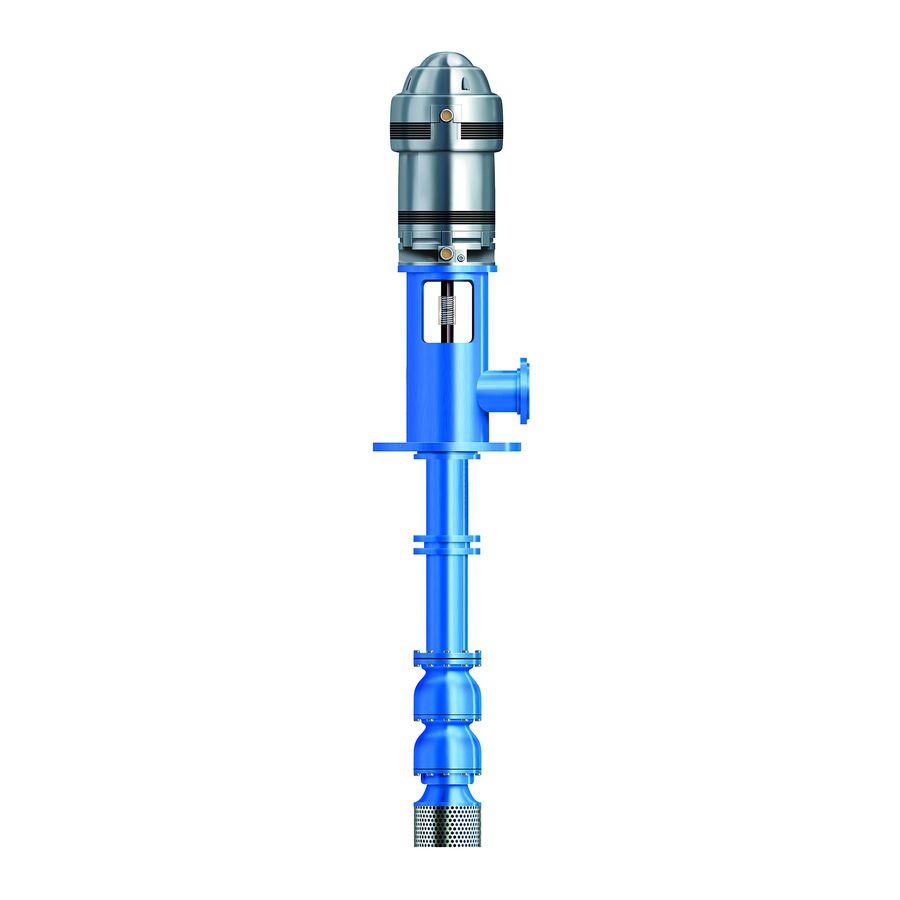
3.1 General description Pumps VIT, VIC and VIDS have few differences. The Model VIT pump is a vertical, industrial, turbine-type pump designed to meet a wide range of appli- cations. The Model VIC is pump VIT inside a barrel with a different discharge head. -
Page 25: Nameplate Information
The code classification marked on the equipment should be in accordance with the specified area where the equipment will be installed. If it is not, please contact your ITT/Goulds representative before proceed- ing. Model VIT, VIC and VIDS Installation, Operation, and Maintenance Manual... - Page 26 Ensure the pump driver and all other auxiliary components meet the required area classifica- tion at the site. If they are not compatible, do not operate the equipment and contact an ITT representative before proceeding. Model VIT, VIC and VIDS Installation, Operation, and Maintenance Manual...
-
Page 27: Installation
Protective covers should be left on all pump openings until the time of actual installation to prevent dirt and foreign objects from entering the pump. Protective coatings should likewise be left on Model VIT, VIC and VIDS Installation, Operation, and Maintenance Manual... -
Page 28: Inspect The Sub-Base
Located in accordance with the dimensions given in the example drawing • Enough space inside the pipe sleeves to allow the final position of the foundation bolts to align with the holes in the sub-base flange Model VIT, VIC and VIDS Installation, Operation, and Maintenance Manual... - Page 29 Level the barrel or sub-base in two directions at 90° on the machined surface to achieve levelness condition indicated in this table. Table 3: Levelness tolerances Commercial 0.4 mm/m | 0.005 inch/ft 0.2 mm/m | 0.002 inch/ft Model VIT, VIC and VIDS Installation, Operation, and Maintenance Manual...
- Page 30 Allow the grout to set at least 48 hours. Tighten the foundation bolts to the torque value provided on the pump general arrangement draw- ing. Model VIT, VIC and VIDS Installation, Operation, and Maintenance Manual...
-
Page 31: Installing The Pump On A Structural-Steel Foundation
Pipe strain ad- versely affects the operation of the pump, which results in physical injury and damage to the equipment. Model VIT, VIC and VIDS Installation, Operation, and Maintenance Manual... - Page 32 Make sure that all piping compo- — nents, valves and fittings, and pump branches are clean prior to assembly. Model VIT, VIC and VIDS Installation, Operation, and Maintenance Manual...
-
Page 33: Pump Installation
Coupling assembly, spacer or non-spacer type Refer to the Certified Pump Outline Drawing for the location of the anchor-bolt holes. Clean the barrel flange if applicable and the bottom of the discharge head base. Model VIT, VIC and VIDS Installation, Operation, and Maintenance Manual... -
Page 34: Installing A Disassembled Pump
ITT the "Pump Installation Instructions (w/ Lifting Clamps)" IOM should be used. Connect these I-beams with threaded rods and nuts so you can clamp them firmly together for the portion to be supported. Model VIT, VIC and VIDS Installation, Operation, and Maintenance Manual... -
Page 35: Column Installation
0.127 mm | 0.005 in. for every 3 m | 10 ft. Apply a thin film of oil to the lineshaft. Install the coupling per Table 4: Lineshaft coupling on page Model VIT, VIC and VIDS Installation, Operation, and Maintenance Manual... - Page 36 Lock screw/lock wire Attach the column to the bowl assembly: Attach a sling to the swivel hoist rings and to the hoist hook. Hoist the column section over the bowl assembly. Model VIT, VIC and VIDS Installation, Operation, and Maintenance Manual...
- Page 37 Slowly lower the bowl and column assembly. 10. Place the supports on the foundation and continue to lower the assembly until the upper column flange comes to rest on the supports. Model VIT, VIC and VIDS Installation, Operation, and Maintenance Manual...
-
Page 38: Installing The Discharge Head
Lower the bowl, column, and head assembly until the discharge-head mounting flange engages the sub base or barrel flange. Secure the discharge head to the sub base or barrel flange. Model VIT, VIC and VIDS Installation, Operation, and Maintenance Manual... -
Page 39: Shaft Sealing Installation And Alignment Summary
Make sure the split gland fits squarely in the stuffing box. A split gland that is not properly seated can cause uneven compression of the packing and damage to the shaft or sleeve. Model VIT, VIC and VIDS Installation, Operation, and Maintenance Manual... - Page 40 Type B (shaft sleeved version) • Type C (shaft sleeved version grease lubricated for longer column length) Bypass line Packing box Packing washer Packing rings Bearing Split gland Figure 17: Type A stuffing box Model VIT, VIC and VIDS Installation, Operation, and Maintenance Manual...
- Page 41 Figure 18: Type B stuffing box Setscrew Sleeve Bypass line Packing box Lantern ring Packing rings Packing washer 10. Grease cup Bearing Split gland O-ring Figure 19: Type C stuffing box Model VIT, VIC and VIDS Installation, Operation, and Maintenance Manual...
- Page 42 Tap each ring down using a split wooden bushing and push the packing ring down firmly until it seals on the shaft and bore of the stuffing box. Stagger the ring joints 90° apart. You can use the split gland as a tamper for the top ring. Model VIT, VIC and VIDS Installation, Operation, and Maintenance Manual...
-
Page 43: Stuffing Box Installation - Alignment Check
Check that the shaft runout is within 0.20 mm | 0.008 in. TIR, or as re- quested by specification. Relocate the driver support using the four alignment lugs when applied. Model VIT, VIC and VIDS Installation, Operation, and Maintenance Manual... -
Page 44: Mechanical Seal Options
Obtain the desired position. Tighten the hold-down bolts and repeat the indicator reading. When precision alignment couplings are supplied maximum TIR is 0.025 mm | 0.001 in. Model VIT, VIC and VIDS Installation, Operation, and Maintenance Manual... - Page 45 Slowly rotate the driver shaft 360°. Check that the face of the seal housing is square with the shaft to within 0.0005" per inch of seal chamber TIR. Model VIT, VIC and VIDS Installation, Operation, and Maintenance Manual...
- Page 46 Obtain the desired position. Tighten the hold-down bolts and repeat the indicator reading. For seal glands that don't have a register fit this check isn't necessary. Model VIT, VIC and VIDS Installation, Operation, and Maintenance Manual...
- Page 47 Install the seal over the shaft and ease it into position against the face of the seal box. Take care when you pass the sleeve and O-ring over the keyways or threads in order to avoid damage to the O-ring. Model VIT, VIC and VIDS Installation, Operation, and Maintenance Manual...
- Page 48 Slide the backup ring assembly over the shaft and position it on the seal. Install the spacer coupling and the driver. Set the seal into position. Adjust the backup ring assembly. Model VIT, VIC and VIDS Installation, Operation, and Maintenance Manual...
- Page 49 4.4 Installing a disassembled pump Back-up rings Bypass to suction Figure 20: Mechanical Seal in Housing Model VIT, VIC and VIDS Installation, Operation, and Maintenance Manual...
-
Page 50: Installing The Enclosing Tube Tension Plate
(5) feels taught and alignment of the bolt holes of the discharge head (1) to the bolt holes of the tension plate (2) is still achievable. NOTICE: Be sure all O-rings maintain a good seal on the headshaft (4) as well as the discharge head (1). Model VIT, VIC and VIDS Installation, Operation, and Maintenance Manual... - Page 51 Secure the tension plate tool (6) by threading on the nuts (8). Do not overtighten the nuts (8) at this time. This is depicted in Figure 24: Tension plate tool on page Model VIT, VIC and VIDS Installation, Operation, and Maintenance Manual...
- Page 52 (2) if a mechanical seal (3) is required. The finished assembly should resemble Figure 26: Tube Tension plate completed on page 51 below. NOTICE: This shim (7) has been sized to maintain adequate tension in the enclosing tube assembly. Model VIT, VIC and VIDS Installation, Operation, and Maintenance Manual...
-
Page 53: Installing A Solid-Shaft Driver
Always disconnect and lock out power to the driver before performing any installa- tion or maintenance tasks. • Electrical connections must be made by certified electricians in compliance with all international, national, state, and local rules. Model VIT, VIC and VIDS Installation, Operation, and Maintenance Manual... - Page 54 If the pump is supplied with an adjustable spacer coupling, install the spacer between the headshaft and the drive shaft hubs. Secure with capscrews and hex nuts. Model VIT, VIC and VIDS Installation, Operation, and Maintenance Manual...
- Page 55 Refer to the general arrangement drawing for the rotor lift setting value. • Improper rotor lift adjustment can cause contact between the rotating and sta- tionary parts. This results in sparks and heat generation. Model VIT, VIC and VIDS Installation, Operation, and Maintenance Manual...
-
Page 56: Installing A Hollow-Shaft Driver
(or gear drive) and is held in place by an adjusting nut. This adjust- ing nut carries all the static and hydraulic thrust of the impellers and shaft, and also provides the adjust- ment for the impeller clearances: Model VIT, VIC and VIDS Installation, Operation, and Maintenance Manual... - Page 57 Lower the drive shaft through the motor-quill shaft and examine closely for dirt or burrs between the shaft ends. 10. Raise the drive shaft and adjusting nut assembly to allow room to install the rigid-flanged coupling. Model VIT, VIC and VIDS Installation, Operation, and Maintenance Manual...
- Page 58 4.4 Installing a disassembled pump 4.4.10.1 Assemble the type AR rigid-flanged coupling Drive shaft Driver key Driver hub Split ring Pump hub Pump key Head shaft Hex nut Capscrew Disassemble the coupling: Model VIT, VIC and VIDS Installation, Operation, and Maintenance Manual...
- Page 59 Make sure that you can remove the key with gentle leverage using a screwdriver. Make sure that the gib key is not so high that it prevents the adjusting nut from seating on the drive coupling. Install the adjusting nut and hand-tighten. Model VIT, VIC and VIDS Installation, Operation, and Maintenance Manual...
- Page 60 1-10 LH 0.12 mm | 0.005 in. 55 mm | 2 in. 1-10 LH 0.12 mm | 0.005 in. 62 mm | 2 in. 1-8 LH 0.15 mm | 0.006 in. 68 mm | 2 Model VIT, VIC and VIDS Installation, Operation, and Maintenance Manual...
-
Page 61: Set Up The Lubrication System
30 to 50 mm 2.19 and larger 55 mm and larger NOTICE: In general applications, ITT recommends synthetic turbine oil ISO VG 32. For more specific da- ta consult ITT. Model VIT, VIC and VIDS Installation, Operation, and Maintenance Manual... -
Page 62: Flush Water System Setup
Before you couple the driver to the pump, verify the proper rotation of the driver by bumping it. The proper rotation for vertical pumps is counterclockwise when viewed from above. Model VIT, VIC and VIDS Installation, Operation, and Maintenance Manual... - Page 63 Watch for signs of trouble. The unit must run at least ten minutes in order to flush out the pump and system. Verify that the unit runs smoothly with no unusual noise, vibration, or over heating. Run the unit for one hour in order to test the system. Model VIT, VIC and VIDS Installation, Operation, and Maintenance Manual...
- Page 64 4.4 Installing a disassembled pump Measurements Reading Value Impeller lift Driver shaft runout Pump head shaft runout Seal housing face runout Seal housing bore runout Megger Vibration Model VIT, VIC and VIDS Installation, Operation, and Maintenance Manual...
-
Page 65: Commissioning, Startup, Operation, And Shutdown
Electrical connections must be made by certified electricians in compliance with all international, national, state, and local rules. • Refer to driver/coupling/gear manufacturer's installation and operation manuals (IOM) for specific instructions and recommendations. Model VIT, VIC and VIDS Installation, Operation, and Maintenance Manual... - Page 66 Bring variable-speed drivers to the rated speed as quickly as possible. • Run a new or rebuilt pump at a speed that provides enough flow to flush and cool the close-running surfaces of the stuffing-box or seal-housing bearing. Model VIT, VIC and VIDS Installation, Operation, and Maintenance Manual...
-
Page 67: Prepare For Startup
For oil-lubricated lineshafts, set the sight feed dripper for the number of drops per minute as direct- ed in 4.4.11 Set up the lubrication system on page 12. For flush water lubricated lineshafts, see the instructions on General Arrangement Drawing. Model VIT, VIC and VIDS Installation, Operation, and Maintenance Manual... -
Page 68: Pump Priming
If the pump fails to reach the correct pressure, perform these steps: Stop the driver. Confirm the minimum submergence. Restart the driver. Monitor the pump while it is operating: Check the pump for bearing temperature, excessive vibration, and noise. Model VIT, VIC and VIDS Installation, Operation, and Maintenance Manual... -
Page 69: Pump Operation Precautions
Cavitation can cause damage to the internal surfaces of the pump. Ensure net positive suction head available (NPSH ) always exceeds NPSH required (NPSH ) as shown on the published performance curve of the pump. Model VIT, VIC and VIDS Installation, Operation, and Maintenance Manual... -
Page 70: Mechanical Seal Leaks
On pump sets with double mechanical seal, apply the required pressure specified in the mechanical seal documentation to the mechanical seal chamber also during standstill. Model VIT, VIC and VIDS Installation, Operation, and Maintenance Manual... -
Page 71: Lubricate The Thrust Pot During A Shutdown Period
This helps to avoid oxidation of the anti-friction bearings during shutdown periods lasting longer than one week. Fill the oil reservoir until the oil runs over the oil retainer tube and down the shaft. Before startup, drain the oil to its required level. Model VIT, VIC and VIDS Installation, Operation, and Maintenance Manual... -
Page 72: Maintenance
Check the pump power. If the pump performance does not satisfy your process requirements, and the process requirements have not changed, then perform these steps: Disassemble the pump. Inspect it. Replace worn parts. Model VIT, VIC and VIDS Installation, Operation, and Maintenance Manual... -
Page 73: Adjust And Replace The Packing
This causes the entire set of packing rings to move away from the bottom of the box without relieving pressure of the packing on the shaft. A small amount of leaking is required in order to prevent overheating. Model VIT, VIC and VIDS Installation, Operation, and Maintenance Manual... -
Page 74: Thrust Pot Lubrication Guidelines
Precautions must be taken to prevent physical injury. The pump may handle hazardous and/or toxic fluids. Proper personal protective equipment should be worn. Pumpage must be handled and disposed of in conformance with applicable environmental regulations. Model VIT, VIC and VIDS Installation, Operation, and Maintenance Manual... -
Page 75: Disassemble The Head And Column
6.4.3 Bowl disassembly The bowl assembly is composed of these parts: • Suction bell • Intermediate bowls • Top bowl • Impellers and securing hardware • Bearings • Pump shaft Model VIT, VIC and VIDS Installation, Operation, and Maintenance Manual... -
Page 76: Remove The Bowl And Impeller Wear Rings
Remove the suction bell bearing by setting the suction bell in a lathe and machining the bearing off. The suction bell bearing can also be removed using bearing pullers to pull the bearings out. Model VIT, VIC and VIDS Installation, Operation, and Maintenance Manual... -
Page 77: Pre-Assembly Inspections
Risk of serious personal injury or property damage. Fasteners such as bolts and nuts are criti- cal to the safe and reliable operation of the product. Ensure appropriate use of fasteners during installation or reassembly of the unit. Model VIT, VIC and VIDS Installation, Operation, and Maintenance Manual... -
Page 78: Reassembly
Wear heat resistant gloves and use the appropriate eye protection in order to prevent injury when you handle hot parts. Apply a thin film of turbine oil to all mating and threaded parts. Model VIT, VIC and VIDS Installation, Operation, and Maintenance Manual... - Page 79 Hold the shaft with a capscrew and washer against the suction bell and drive the taper collet into place with a collet driver. NOTICE: Collet driver should slide on the shaft and knock firmly the taper collet. Model VIT, VIC and VIDS Installation, Operation, and Maintenance Manual...
-
Page 80: Installing The Keyed Bowl Assembly
The size of the pump is stated on the nameplate and on the Certified Pump Outline Drawing. Pump size X dimension (inches) X dimension (millimeters) 1.31 33.27 1.37 34.80 1.37 34.80 1.37 34.80 1.37 34.80 1.37 34.80 1.37 34.80 1.37 34.80 1.37 34.80 Model VIT, VIC and VIDS Installation, Operation, and Maintenance Manual... -
Page 81: Tightening Torques
16D - Bell 1.75 44.45 16D - Bowl 2.75 69.85 2.75 69.85 0.87 22.10 4.50 114.30 6.25 158.75 6.6.6 Tightening torques Refer to 10.1 Tightening torque tables on page 101 Model VIT, VIC and VIDS Installation, Operation, and Maintenance Manual... -
Page 82: Troubleshooting
Check the engagement of the mo- tor coupling. The impellers are too high (semi-open Reset the impeller adjustment. See Instal- construction only). lation for details. Model VIT, VIC and VIDS Installation, Operation, and Maintenance Manual... - Page 83 There is excessive leakage from The packing is defective. Replace any packing that is worn or dam- the stuffing box. aged. The wrong kind of packing was used. Consult an ITT representative. Model VIT, VIC and VIDS Installation, Operation, and Maintenance Manual...
- Page 84 Install a bypass flush line in order to hold ess liquid cooling and crystallizing or the liquid temperature around the seal partially solidifying in the seal area. above the crystallization point. Model VIT, VIC and VIDS Installation, Operation, and Maintenance Manual...
- Page 85 The seal is running too hot. Check for possible rubbing of the seal components. Recirculation or a bypass line may be necessary. The wrong kind of seal was used. Consult an ITT representative. Model VIT, VIC and VIDS Installation, Operation, and Maintenance Manual...
-
Page 86: Parts Listings And Cross-Sectionals
8 Parts Listings and Cross-Sectionals 8 Parts Listings and Cross-Sectionals 8.1 VIT product lube (includes VIDS detail) This image shows the VIT with motor support (two-piece head construction): 760M 739/735 760L 760/735 760A 760B 735A 760C 760E 760F 760K This pump has these features: •... - Page 87 Bowl bearing Impeller Bowl wear ring Impeller wear ring Suction bell Suction bearing Sand collar Basket type strainer Coupling guard Retaining ring Thrust ring Hex nut Stud VIDS specific parts Model VIT, VIC and VIDS Installation, Operation, and Maintenance Manual...
-
Page 88: Vit Enclosed Lineshaft
8.2 VIT enclosed lineshaft 8.2 VIT enclosed lineshaft 760M 735 614 760L 760A 760B 760E 760F 760K Model VIT, VIC and VIDS Installation, Operation, and Maintenance Manual... - Page 89 8.2 VIT enclosed lineshaft 758A 743B 743A 1. Oil lube line 759B 735B 735C 758A 743A 743B 1. Water flush line Model VIT, VIC and VIDS Installation, Operation, and Maintenance Manual...
- Page 90 Discharge bowl required for all lube oil lube and water flush lines with bowl sizes 30" and smaller Head Motor support Headshaft Hub motor Adjusting plate Pump hub Gland Packing Model VIT, VIC and VIDS Installation, Operation, and Maintenance Manual...
- Page 91 758A Capscrew Socket head capscrew 759B Capscrew Capscrew 760A Column/head capscrew 760B Column/column capscrew 760C Column/bowl capscrew 760D Bowl/discharge bowl capscrew 760E Bowl/bowl capscrew 760F Bowl/bell capscrew 760K Strainer capscrew Model VIT, VIC and VIDS Installation, Operation, and Maintenance Manual...
- Page 92 Every 3 m | 10 ft. up to 12 m | 40 ft. of column • Every 12 m | 40 ft. over 12 m | 40 ft. of column Model VIT, VIC and VIDS Installation, Operation, and Maintenance Manual...
-
Page 93: Vic-T
8.3 VIC-T 759B 757B 759C 757B 747J 757H 760A 758D 758C 735/760B 743K 743A 760C 760E 760F Label Part name Spacer coupling Mechanical seal Seal, by-pass return VSS motor Head Model VIT, VIC and VIDS Installation, Operation, and Maintenance Manual... - Page 94 759B Driver hub socket capscrew 759C Pump hub socket capscrew Capscrew 760A Column/head capscrew 760C Column/bowl capscrew 760E Bowl/bowl capscrew 760F Bowl/bell capscrew Setscrew with ring Seal housing bearing Seal gland Seal housing Model VIT, VIC and VIDS Installation, Operation, and Maintenance Manual...
-
Page 95: Vic-L
8.4 VIC-L 759B 757B 759C 757C 757H 760A 735/760B 758D 758C 649/774 743K 743A 760C 760E 760F 774/680 Label Part name Spacer coupling Mechanical seal VSS motor Vent connection Barrel vent Model VIT, VIC and VIDS Installation, Operation, and Maintenance Manual... - Page 96 759B Driver hub socket capscrew 759C Pump hub socket capscrew Align lug capscrew 760A Column/head capscrew 760B Column/column capscrew 760C Column/bowl capscrew 760E Bowl/bowl capscrew 760F Bowl/bell capscrew Setscrew with ring Model VIT, VIC and VIDS Installation, Operation, and Maintenance Manual...
- Page 97 8.4 VIC-L Label Part name Seal housing bearing Seal gland Seal housing Model VIT, VIC and VIDS Installation, Operation, and Maintenance Manual...
-
Page 98: Annex I
Lifting strap chocking barrel outside diameter Lifting cables attached to four hoist rings Figure 29: Barrel initial hoisting Step 2 Maintain clearance here during lift Figure 30: Barrel intermediate hoisting Model VIT, VIC and VIDS Installation, Operation, and Maintenance Manual... - Page 99 Using the crane, jack screws and binders level the barrel top plate and maintain elevation. Figure 32: Anchoring of the barrel on the floor for initial works Model VIT, VIC and VIDS Installation, Operation, and Maintenance Manual...
- Page 100 Figure 33: Barrel initial leveling Step 6 Adjust anchor bolt nuts Adjust leveling screws and anchor bolts simultaneously to achieve required level and elevation conditions Figure 34: Barrel in-process leveling Model VIT, VIC and VIDS Installation, Operation, and Maintenance Manual...
- Page 101 Use chain binders to maintain top plate level during concrete pouring Figure 35: Concrete pouring Step 8 Install anchor bolts prior to final concrete pour Figure 36: Final concrete pouring Model VIT, VIC and VIDS Installation, Operation, and Maintenance Manual...
- Page 102 9.1 Example of VIC-L barrel installation Step 9 Pour grout Wait until concrete reaches full design strength, then torque anchor bolts Figure 37: Top plate grouting and final leveling check Model VIT, VIC and VIDS Installation, Operation, and Maintenance Manual...
-
Page 103: Annex Ii
4830 | 3562 8855 | 6530 95 | 3-3/4 7965 | 5874 5310 | 3916 9736 | 7180 73 | 2-7/8 9138 | 6739 6093 | 4493 11169 | 8237 Model VIT, VIC and VIDS Installation, Operation, and Maintenance Manual... - Page 104 64 | 2-1/2 8897 | 6561 7710 | 5686 9489 | 6998 8897 | 6561 64 | 2-1/2 9883 | 7288 8564 | 6316 10542 | 7774 9883 | 7288 Model VIT, VIC and VIDS Installation, Operation, and Maintenance Manual...
- Page 105 13266 | 9783 57 | 2-1/4 12345 | 9104 11797 | 8700 7596 | 5602 14530| 10715 60 | 2-3/8 14605 | 10771 12455 | 9185 8988 | 6628 17191 | 12678 Model VIT, VIC and VIDS Installation, Operation, and Maintenance Manual...
- Page 106 27611 | 20362 16992 | 12531 32498 | 23966 76 | 3 30106 | 22202 18527 | 13663 35434 | 26131 Torque values provided assume fastener lubricant applied, k-factor = 0.15 Model VIT, VIC and VIDS Installation, Operation, and Maintenance Manual...
-
Page 107: Ce Declaration Of Conformity
11 CE Declaration of Conformity 11 CE Declaration of Conformity 11.1 CE Declaration of Conformity Model VIT, VIC and VIDS Installation, Operation, and Maintenance Manual... - Page 108 11.1 CE Declaration of Conformity Model VIT, VIC and VIDS Installation, Operation, and Maintenance Manual...
- Page 109 Camino La Colina # 1448 Condominio Industrial El Rosal Huechuraba Santiago 8580000 Chile Middle East and Africa ITT - Goulds Pumps +30 210-677-0770 +30 210-677-5642 Achileos Kyrou 4 Neo Psychiko 115 25 Athens Greece Model VIT, VIC and VIDS Installation, Operation, and Maintenance Manual...
- Page 110 Visit our website for the latest version of this document and more information: http://www.gouldspumps.com ITT Goulds Pumps, Inc. 240 Fall Street Seneca Falls, NY 13148 Form IOM.VIT.VIC.VIDS.en-US.2021-06 ©2021 ITT Inc. The original instruction is in English. All non-English instructions are translations of the original instruction.
Need help?
Do you have a question about the VIT and is the answer not in the manual?
Questions and answers