Table of Contents
Advertisement
Advertisement
Table of Contents

Subscribe to Our Youtube Channel
Related Manuals for Goulds Pumps VIT


Summary of Contents for Goulds Pumps VIT
- Page 1 Installation, Operation, and Maintenance Model VIT...
-
Page 3: Table Of Contents
Impeller adjustment ......................46 Adjust the impeller for a solid-shaft driver ................48 Install a hollow-shaft driver ....................49 Assemble the type AR rigid-flanged coupling ..............51 Complete the hollow-shaft driver installation ..............52 Model VIT Installation, Operation, and Maintenance... - Page 4 Pump shaft setup dimensions .................... 69 Troubleshooting ........................71 Operation troubleshooting ..................... 71 Parts Listings and Cross-Sectionals ................... 74 VIT FF product lube ......................74 VIT FF enclosed lineshaft ..................... 76 Local ITT Contacts ........................ 79 Regional offices ........................79...
-
Page 5: Introduction And Safety
Risk of injury and/or property damage. Operating a pump in an inappropriate application can cause over pressurization, overheating, and/or unstable operation. Do not change the service application without the approval of an authorized ITT representative. NOTICE: Save this manual for future reference and keep it readily available. Model VIT Installation, Operation, and Maintenance... -
Page 6: Safety Terminology And Symbols
The Ex symbol indicates safety regulations for Ex-approved products when used in atmospheres that are potentially explosive or flammable. Environmental safety The work area Always keep the pump station clean to avoid and/or discover emissions. Model VIT Installation, Operation, and Maintenance... -
Page 7: User Health And Safety
• Make sure that the product is isolated from the power supply and cannot be energized by mistake. This guideline also applies to the control circuit. • Make sure that the thermal contacts are connected to a protection circuit according to the product approvals, and that they are in use. Model VIT Installation, Operation, and Maintenance... - Page 8 • Beware of the risk of a sudden start if the product is used with an automatic level control. • Beware of the starting jerk, which can be powerful. • Rinse the components in water after you disassemble the pump. • Do not exceed the maximum working pressure of the pump. Model VIT Installation, Operation, and Maintenance...
-
Page 9: Safety Regulations For Ex-Approved Products In Potentially Explosive Atmospheres
• The Ex-approved product must never run dry during normal operation. Dry running during service and inspection is only permitted outside the classified area. • Never start a pump with a closed suction valve or blocked suction line. Model VIT Installation, Operation, and Maintenance... -
Page 10: Product Approval Standards
• The monitoring equipment incorporated in the product is correctly connected and in use. • All service and repair work is done by ITT-authorized personnel. • Genuine ITT parts are used. • Only Ex-approved spare parts and accessories authorized by ITT are used in Ex-approved products. Model VIT Installation, Operation, and Maintenance... - Page 11 • Material damages • Economic losses Warranty claim ITT products are high-quality products with expected reliable operation and long life. However, should the need arise for a warranty claim, then contact your ITT representative. Model VIT Installation, Operation, and Maintenance...
-
Page 12: Transportation And Storage
Use suitable lifting devices attached to the component or sub-assembly lifting pump lugs or suitable eyebolts through the component flanges. A disassembled pump Use suitable lifting devices attached to the component lifting lugs or suitable eyebolts through the component flanges. Model VIT Installation, Operation, and Maintenance... - Page 13 Transportation and Storage Examples 1. Horizontal position 2. Vertical position Figure 1: VIT lifted from horizontal to vertical (for pumps up to 15 feet [4.6 meters] in length) Model VIT Installation, Operation, and Maintenance...
-
Page 14: Pump Storage Requirements
1. Horizontal position 2. Intermediate position 3. Vertical position Figure 2: VIT lifted from horizontal to vertical (for pumps up to 30 feet [9.1 meters] in length) Pump storage requirements Requirements Vertical pumps require proper preparation for storage and regular maintenance during storage. -
Page 15: Prepare The Pump For Long-Term Storage
6. Provide a small ventilation hole approximately 12.0 mm | 0.5 in. diameter. 7. Provide a roof or shed shelter in order to protect the unit from direct exposure to the elements. Model VIT Installation, Operation, and Maintenance... -
Page 16: Product Description
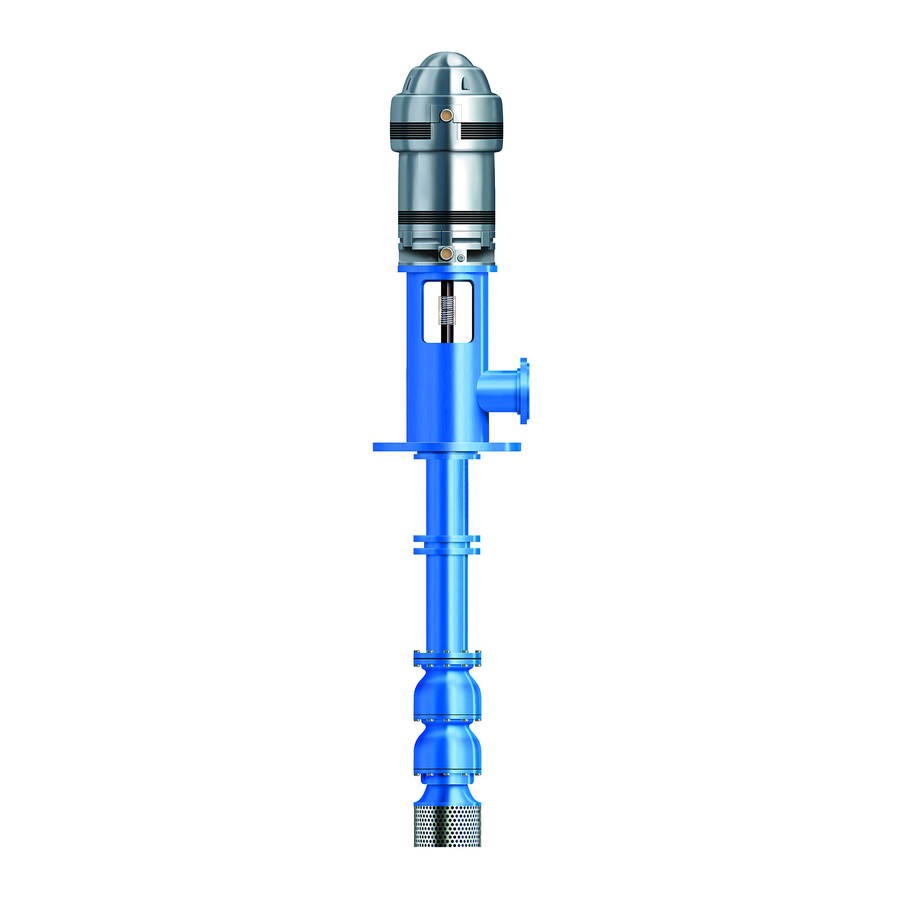
Product Description Product Description General description The Model VIT pump is a vertical, industrial, turbine-type pump designed to meet a wide range of applications. This pump has these capabilities: • Capacities up to 70,000 gpm (15,900 m3/h) • Heads up to 4,500 ft. (1,372 m) •... -
Page 17: Nameplate Information
Purchase order number of the customer MODEL Pump model SIZE Size of the pump R.P.M. Rated pump speed, revolutions per minute ROTOR LIFT Axial lift of the pump shaft and impellers RATED FLOW Rated pump flow, gpm (m /hr) Model VIT Installation, Operation, and Maintenance... - Page 18 Ensure that the code classifications on the pump are compatible with the specific environment in which the equipment is to be installed. If they are not compatible, do not operate the equipment and contact an ITT representative before proceeding. Model VIT Installation, Operation, and Maintenance...
-
Page 19: Installation
• Located in accordance with the dimensions given in the example drawing • Enough space inside the pipe sleeves to allow the final position of the foundation bolts to align with the holes in the sub-base flange Model VIT Installation, Operation, and Maintenance... - Page 20 3. Carefully lower the barrel or sub-base onto the foundation bolts and hand-tighten the bolt nuts. 4. Use a machinist's level in order to level the barrel or sub-base or a machine surface of the discharge head using metal plates and leveling screws. Model VIT Installation, Operation, and Maintenance...
-
Page 21: Install The Pump On A Structural-Steel Foundation
1. Locate the barrel and pump directly over - or as near as possible to - the main building members, beams, or walls. 2. Bolt the barrel or sub-base to the support in order to avoid distortion, prevent vibration, and retain proper alignment. 3. Level the barrel or sub-base using shims. Model VIT Installation, Operation, and Maintenance... -
Page 22: Piping Checklists
• Misalignment between the pump and the drive unit • Wear on the pump bearings, seal, and shafting Check that only necessary fittings This helps to minimize friction losses. are used. Model VIT Installation, Operation, and Maintenance... -
Page 23: Install A Partially-Assembled Pump
Make sure that the shackles, eyebolts, and sling are rated to handle in excess of the pump weight. See the outline drawing. 4. Carefully guide the unit so that it does not strike the sides of the sub-base or foundation. Model VIT Installation, Operation, and Maintenance... -
Page 24: Install The Bowl Assembly
4. Place a suitable hoist or derrick over the barrel opening with the hook in the center. 5. Install two threaded eyebolts through the discharge bowl bolt holes 180º apart. 6. Attach a sling to the eyebolts and hoist it into position over the foundation opening. Model VIT Installation, Operation, and Maintenance... -
Page 25: Install The Threaded Coupling
The average TIR should be less than 0.0005 in. (0.013 mm) per ft. (0.305 m) and not exceed 0.005 in. (0.127 mm) for every 10 ft. (3 m). 2. Apply a thin film of oil to the lineshaft. 3. Install the coupling: Shaft threads are left hand. Model VIT Installation, Operation, and Maintenance... - Page 26 5. Run the upper lineshaft into the coupling and hand-tighten. Do not apply wrenches on the bearing journal surfaces. For an illustration of the threaded coupling, see the VIT-FF product lube in the Parts List chapter. Keyed 1. Insert the key into the pump shaft.
-
Page 27: Install The Enclosed Lineshaft
5. Run the upper lineshaft into the coupling and hand-tighten. Do not apply wrenches on the bearing journal surfaces. For an illustration of the threaded coupling, see the VIT-FF product lube in the Parts List chapter. Model VIT Installation, Operation, and Maintenance... - Page 28 10. Pour one quart of light turbine oil into the top tubing section and screw the tube bearing into the top length until it bottoms, ready to receive the next length of tubing assembly. Model VIT Installation, Operation, and Maintenance...
-
Page 29: Install The Discharge Head
• Make sure the split gland fits squarely in the stuffing box. A split gland that is not properly seated can cause uneven compression of the packing and damage to the shaft or sleeve. • Packed stuffing boxes are not allowed in an ATEX-classified environment. Model VIT Installation, Operation, and Maintenance... - Page 30 The stuffing box installation has three types: • Type A • Type B • Type C 1. Bypass line 2. Packing washer 3. Bearing 4. Packing box 5. Packing rings 6. Split gland Figure 7: Type A stuffing box Model VIT Installation, Operation, and Maintenance...
- Page 31 Installation 1. Setscrew 2. Bypass line 3. Packing washer 4. Bearing 5. O-ring 6. Sleeve 7. Packing box 8. Packing rings 9. Split gland Figure 8: Type B stuffing box Model VIT Installation, Operation, and Maintenance...
-
Page 32: Install The Type A And B Stuffing Boxes
Stagger the ring joints 90° apart. You can use the split gland as a tamper for the top ring. 10. Install the split gland and thread the nuts on the split gland studs. Model VIT Installation, Operation, and Maintenance... -
Page 33: Install The Type C Stuffing Box
These are the mechanical seal options for this pump: • Cartridge mechanical seal • Conventional inside component mechanical seal • Conventional outside component mechanical seal • High-pressure seal • Dual mechanical seal Model VIT Installation, Operation, and Maintenance... -
Page 34: Install The Mechanical Seal
5. Before you make the final connections of the sealing-liquid pressurizing lines, make sure the seal housing and all sealing-liquid lines are flushed free of dirt, scale, and other particles. 6. Install the driver and coupling. 7. Take these flatness and concentricity measurements: Model VIT Installation, Operation, and Maintenance... - Page 35 3. If the indicator reads higher than 0.002 in. (0.05 mm) TIR, loosen the four driver hold-down bolts and relocate the driver on the motor base register. 4. Obtain the desired position. 5. Tighten the hold-down bolts and repeat the indicator reading. Model VIT Installation, Operation, and Maintenance...
- Page 36 2. Place the stylus at the top surface of the seal gland, or at the top surface of the seal housing. 3. Slowly rotate the driver shaft 360°. 4. Check that the face of the seal housing is square with the shaft to within 0.002 in. (0.05 mm) TIR. Model VIT Installation, Operation, and Maintenance...
- Page 37 3. If the indicator reads higher than 0.004 in. (0.10 mm) TIR, loosen the four driver hold-down bolts and relocate the driver on the motor base register. 4. Obtain the desired position. 5. Tighten the hold-down bolts and repeat the indicator reading. Model VIT Installation, Operation, and Maintenance...
-
Page 38: Assemble A Single Inside-Mounted Mechanical Seal
Assemble a single inside-mounted mechanical seal Single inside-mounted mechanical seals have these characteristics: • They are cartridge seals. • They have glands and sleeves. • They are assembled as a unit by the seal manufacturer. Model VIT Installation, Operation, and Maintenance... -
Page 39: Assemble A Single Outside-Mounted Mechanical Seal
Before you start the pump, make sure that the spring gap and the distance from the face of the stuffing box to the collar are the same as shown on the seal assembly drawing. Model VIT Installation, Operation, and Maintenance... -
Page 40: Install The High-Pressure Seal
Slide the backup ring assembly over the shaft and position it on the seal. 2. Install the spacer coupling and the driver. 3. Set the seal into position. 4. Check the TIR on the headshaft above the mechanical seal. 5. Adjust the backup ring assembly. Model VIT Installation, Operation, and Maintenance... -
Page 41: Install The Dual Mechanical Seals
8. Seat the gland ring and gland gasket against the face of the seal housing: a) Tighten the nuts or bolts evenly and firmly. b) Make sure that the gland ring is not cocked. Model VIT Installation, Operation, and Maintenance... -
Page 42: Install The Tube Tension Plate
1. Lubricate the tube threads and the underside of the tension-plate flange with a thread compound. 2. Thread the tension plate onto the enclosing tube nipple manually until its shoulder rests on the discharge head. Model VIT Installation, Operation, and Maintenance... -
Page 43: Tension The Enclosing Tube
Table 4: Tube weight Tube diameter in inches (millimeters) Weight in pounds (kilograms) per foot of length 1.25 (31.75) 2.99 (1.36) 1.50 (38.10) 3.63 (1.65) 2.00 (50.80) 5.02 (2.28) 2.50 (63.50) 7.66 (3.47) 3.00 (76.20) 10.25 (4.65) Model VIT Installation, Operation, and Maintenance... -
Page 44: Install The Tension Nut
If the tube is... Then... Too short Replace the tube with a longer tube of the correct length. Too long Cut the tube to the correct length and re-thread it. 7. Reinstall and re-level the pump. Model VIT Installation, Operation, and Maintenance... -
Page 45: Install A Solid-Shaft Driver
The coupling between the driveshaft and the discharge-head shaft can either be a non-spacer type or a spacer type. The spacer type is used on pumps furnished with a mechanical seal to permit servicing of the seal without the removal of the driver. Model VIT Installation, Operation, and Maintenance... - Page 46 2. Driver key, supplied by motor vendor 3. Driver hub 4. Adjusting plate 5. Pump hub 6. Pump key 7. Headshaft 8. Hex nut 9. Capscrew 10. Split ring Figure 13: Non-spacer type coupling Model VIT Installation, Operation, and Maintenance...
- Page 47 Secure the motor with capscrews. 5. On drivers with a non-reverse ratchet or pins, manually turn the driver shaft clockwise when viewed from the top, until the non-reverse ratchet or pins fully engage. Model VIT Installation, Operation, and Maintenance...
-
Page 48: Install The Coupling Hub
Example figures Impeller adjustment is identical for all drivers. Adjust the impeller by turning the adjusting plate. At location A in these two figures, measure the impeller adjustment before you tighten the coupling capscrews: Model VIT Installation, Operation, and Maintenance... - Page 49 2. Driver key, supplied by the motor vendor 3. Driver hub 4. Pump hub 5. Pump key 6. Headshaft 7. Capscrew 8. Adjusting plate 9. Hex nut 10. Split ring Figure 15: Adjustable coupling (Type A) Model VIT Installation, Operation, and Maintenance...
-
Page 50: Adjust The Impeller For A Solid-Shaft Driver
4. Set the seal: 1. Securely tighten all setscrews in the collar. 2. Remove the spacer between the gland plate and the collar. 3. Retain the spacer for future resetting of the seal. Model VIT Installation, Operation, and Maintenance... -
Page 51: Install A Hollow-Shaft Driver
Install the driver support on the discharge head and secure it with capscrews. 2. Inspect the driver: a) Attach a sling to the lifting lugs of the driver and hoist the motor. b) Inspect the mounting surface, register, and shaft extension. c) Clean these surfaces thoroughly. Model VIT Installation, Operation, and Maintenance... - Page 52 9. Lower the drive shaft through the motor-quill shaft and examine closely for dirt or burrs between the shaft ends. 10. Raise the drive shaft and adjusting nut assembly to allow room to install the rigid-flanged coupling. Model VIT Installation, Operation, and Maintenance...
-
Page 53: Assemble The Type Ar Rigid-Flanged Coupling
This ensures that the driver and pumpshaft ends will not contact each other when the coupling is completely assembled. 2. Insert the pump key into the pumpshaft keyway and slide the pump hub onto the pumpshaft. Position the hub so that the threaded shaft end is exposed. Model VIT Installation, Operation, and Maintenance... -
Page 54: Complete The Hollow-Shaft Driver Installation
Make sure that you can remove the key with gentle leverage using a screwdriver. 5. Make sure that the gib key is not so high that it prevents the adjusting nut from seating on the drive coupling. 6. Install the adjusting nut and hand-tighten. Model VIT Installation, Operation, and Maintenance... -
Page 55: Adjust The Impeller For A Hollow-Shaft Driver
1-10 LH 0.005 in. (0.12 mm) in. (62 mm) 1-10 LH 0.005 in. (0.12 mm) in. (68 mm) 1-8 LH 0.006 in. (0.15 mm) 1. Lower impeller 2. Raise impeller 3. Correct impeller rotation Model VIT Installation, Operation, and Maintenance... -
Page 56: Set Up The Lubrication System
It is very important that the initial run is at least ten minutes in duration in order to completely flush the pump. If possible, check the cleanliness of the pumped fluid and piping. If you are present during the installation, check that the sump, barrel, and piping are clean. Model VIT Installation, Operation, and Maintenance... - Page 57 Verify that the unit runs smoothly with no unusual noise, vibration, or over heating. Run the unit for one hour in order to test the system. Measurements Reading Value Impeller lift Shaft runout Megger Vibration Model VIT Installation, Operation, and Maintenance...
-
Page 58: Commissioning, Startup, Operation, And Shutdown
• Flush and clean the system thoroughly to remove dirt or debris in the pipe system in order to prevent premature failure at initial startup. • Bring variable-speed drivers to the rated speed as quickly as possible. Model VIT Installation, Operation, and Maintenance... -
Page 59: Prepare For Startup
Drops per minute per 100 ft. (39 m) of shaft ¾ to 1 in. (19 mm to 25 mm) to 1 in. (30 mm to 49 mm) in. and larger (55 mm and larger) Model VIT Installation, Operation, and Maintenance... -
Page 60: Pump Priming
5. If the pump fails to reach the correct pressure, perform these steps: a) Stop the driver. b) Confirm the minimum submergence. c) Restart the driver. 6. Monitor the pump while it is operating: a) Check the pump for bearing temperature, excessive vibration, and noise. Model VIT Installation, Operation, and Maintenance... -
Page 61: Pump Operation Precautions
Do not expose an idle pump to freezing conditions. Drain all liquid that is inside the pump and any auxiliary equipment. Failure to do so can cause liquid to freeze and damage the pump. Model VIT Installation, Operation, and Maintenance... -
Page 62: Mechanical Seal Leaks
3. If the driver is not equipped with a non-reverse ratchet (NRR), be certain that the unit is completely stopped before you restart the pump. Lubricate the thrust pot during a shutdown period 1. Completely immerse the bearings in oil. Model VIT Installation, Operation, and Maintenance... - Page 63 This helps to avoid oxidation of the anti-friction bearings during shutdown periods lasting longer than one week. 2. Fill the oil reservoir until the oil runs over the oil retainer tube and down the shaft. Before startup, drain the oil to its required level. Model VIT Installation, Operation, and Maintenance...
-
Page 64: Maintenance
• Check the pump power. If the pump performance does not satisfy your process requirements, and the process requirements have not changed, then perform these steps: 1. Disassemble the pump. 2. Inspect it. 3. Replace worn parts. Model VIT Installation, Operation, and Maintenance... -
Page 65: Adjust And Replace The Packing
1. Stop the pump and allow the packing to cool. 2. Restart the pump. 3. Repeat these steps until two drops of liquid per second comes through. 4. If this fails to fix the problem, then you must replace the packing. Model VIT Installation, Operation, and Maintenance... -
Page 66: Thrust Pot Lubrication Guidelines
• Risk of severe physical injury or death from explosion of trapped liquid. Never use heat to remove parts unless explicitly stated in this manual. Model VIT Installation, Operation, and Maintenance... -
Page 67: Disassemble The Head And Column
5. Slide the impeller off the pump shaft. 6. Repeat these steps until the bowl assembly is completely disassembled. Disassemble the keyed bowl 1. Remove the capscrews that secure the top bowl to the intermediate bowl. Model VIT Installation, Operation, and Maintenance... -
Page 68: Remove The Turbine Bowl And Impeller Wear Rings
Replacement guidelines Casing check and replacement WARNING: Risk of death or serious injury. Leaking fluid can cause fire and/or burns. Inspect and ensure gasket sealing surfaces are not damaged and repair or replace as necessary. Model VIT Installation, Operation, and Maintenance... -
Page 69: Reassembly
1. Place the chamfered face of the bowl or impeller wear ring towards the ring seat and press the ring into the seat. 2. Use an arbor press or equivalent and make sure the ring is flush with the edge or the wear ring seat. Model VIT Installation, Operation, and Maintenance... -
Page 70: Install The Bowl, Suction Bell, And Lineshaft Bearings
4. Install the impeller: a) Slide the first impeller over the shaft until it seats on the suction bell. Model VIT Installation, Operation, and Maintenance... -
Page 71: Install The Keyed Bowl Assembly
The size of the pump is stated on the nameplate and on the Certified Pump Outline Drawing. Pump size X dimension (inches) X dimension (millimeters) 1.31 33.27 1.37 34.80 1.37 34.80 1.37 34.80 1.37 34.80 1.37 34.80 1.37 34.80 Model VIT Installation, Operation, and Maintenance... - Page 72 1.75 44.45 2.12 53.85 2.12 53.85 2.25 57.15 2.12 53.85 2.75 69.85 2.75 69.85 2.75 69.85 16D - Bell 1.75 44.45 16D - Bowl 2.75 69.85 2.75 69.85 0.87 22.10 4.50 114.30 6.25 158.75 Model VIT Installation, Operation, and Maintenance...
-
Page 73: Troubleshooting
The impellers are rotating too fast. Check the frequency on the motor. The pump and driver are misaligned. Realign the pump and driver. The discharge head is not properly vented. Open the vent. Model VIT Installation, Operation, and Maintenance... - Page 74 The seal faces are scored from foreign Install a strainer, and then filter or cyclone the particles between the faces. separator as required in order to filter out any foreign particles. Model VIT Installation, Operation, and Maintenance...
- Page 75 The seal is running too hot. Check for possible rubbing of the seal compo- nents. Recirculation or a bypass line may be necessary. The wrong kind of seal was used. Consult an ITT representative. Model VIT Installation, Operation, and Maintenance...
-
Page 76: Parts Listings And Cross-Sectionals
Parts Listings and Cross-Sectionals Parts Listings and Cross-Sectionals VIT FF product lube This image shows the VIT-FF with motor support (two-piece head construction): This pump has these features: • Flanged adjustable coupling • Standard stuffing box • Flanged column with integral bearing retainer and lineshaft bearing •... - Page 77 Thrust ring Hex nut Stud Pipe plug Socket head capscrew Capscrew 760A Column/head capscrew 760B Column/column capscrew 760C Column/bowl capscrew 760E Bowl/bowl capscrew 760F Bowl/bell capscrew 760K Strainer capscrew 760L Support head capscrew Gasket Model VIT Installation, Operation, and Maintenance...
-
Page 78: Vit Ff Enclosed Lineshaft
Tension plate, oil lube and water flush Tension plate – oil lubricated Tension plate – water flushed Tube stabilizer Tube stabilizer B1.1 Integral tube stabilizer (welded to column) Tube stabilizer B2.1 Tube stabilizer (optional on duplicate pumps) Model VIT Installation, Operation, and Maintenance... - Page 79 Retaining ring Thrust ring Hex nut Stud Pipe plug Socket head capscrew Capscrew 760A Column/head capscrew 760B Column/column capscrew 760C Column/bowl capscrew 760D Bowl/discharge bowl capscrew 760E Bowl/bowl capscrew 760F Bowl/bell capscrew 760K Strainer capscrew Model VIT Installation, Operation, and Maintenance...
- Page 80 760M Motor/support capscrew Lubricator assembly Stabilizers provided: • Every 10 ft. (3 m) up to 40 ft. (12 m) of column • Every 40 ft. (12 m) over 40 ft. (12 m) of column Model VIT Installation, Operation, and Maintenance...
-
Page 81: Local Itt Contacts
Camino La Colina # 1448 Condominio Industrial El Rosal Huechuraba Santiago 8580000 Chile Middle East and Africa ITT - Goulds Pumps +30 210-677-0770 +30 210-677-5642 Achileos Kyrou 4 Neo Psychiko 115 25 Athens Greece Model VIT Installation, Operation, and Maintenance... - Page 82 Visit our website for the latest version of this document and more information: www.gouldspumps.com ITT - Goulds Pumps Vertical Products Operation 3951 Capitol Avenue City of Industry, CA 90601-1734 Form IOM.VIT-en-US.2018-02 © 2018 ITT Corporation The original instruction is in English. All non-English instructions are translations of the original...
Need help?
Do you have a question about the VIT and is the answer not in the manual?
Questions and answers