
Related Manuals for Fisher Scientific accumet XL150 accumet XL200 accumet XL250 accumet XL500 accumet XL600


Summary of Contents for Fisher Scientific accumet XL150 accumet XL200 accumet XL250 accumet XL500 accumet XL600
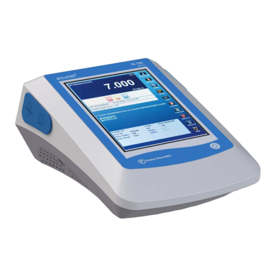
- Page 1 Reference Guide Fisher Scientific accumet Excel (XL) ® Benchtop Meters XL150 ● XL200 ● XL250 ● XL500 ● XL600 68X623601 Rev 0 October 2012...
-
Page 2: Table Of Contents
Table of Contents INTRODUCTION ............................. 4 TOUCH SCREEN & ICONS ..........................5 CONNECTIONS .............................. 8 ELECTRODE BRACKET & ARM ASSEMBLY ....................... 9 POWER ON/OFF ............................10 SYSTEM SETUP ............................11 ADMINISTRATION & USER ID ........................12 PARAMETER SETUP: SAMPLE ID ........................14 PARAMETER SETUP: AUTO READ MODE ..................... - Page 3 OUR OPERATION ............................49 SOUR OPERATION ............................50 FIRMWARE UPGRADE ..........................51 SPECIFICATIONS ............................54 REPLACEMENTS & ACCESSORIES ......................... 57 WARRANTY ..............................59 RETURN OF ITEMS ............................60 NOTICE OF COMPLIANCE ..........................61 DECLARATION OF CONFORMITY ......................... 62...
-
Page 4: Introduction
The chart below lists the parameters served for the various models: Intended Use: Fisher Scientific accumet XL150, XL200, XL250, XL500, and XL600 models are designed for measurement and monitoring of water-based, electrochemical parameters using replaceable sensors. Designated use of these instruments is exclusively for measurement in indoor, laboratory environments. -
Page 5: Touch Screen & Icons
TOUCH SCREEN & ICONS The Fisher Scientific accumet XL150 / XL200 / XL250 / XL500 / XL600 series benchtop meters operate with a high performance TFT color touch screen. The touch screen can be controlled by a finger or an optional USB mouse. - Page 6 About: Provides information about the instrument such as software version and serial number. Single Channel: Use to display one measurement mode. Note: Single Channel is required to access the Standardization mode, Printing function, and On-screen graphing. Multi Channel: Use to display measurement mode of multiple channels simultaneously. Not available with XL150. Display Setup: Use to configure the display options and select input parameters.
- Page 7 Stirrer A: Provides On/Off control of optional stirring probe (13-620-BSP) that is connected to Stirrer port A located in rear of unit. Stirrer B: Provides On/Off control of optional stirring probe (13-620-BSP) connected to Stirrer port B located on the left hand side of unit. IExplorer: Internet Explorer mobile browser for use with RJ45 port.
-
Page 8: Connections
CONNECTIONS Prior to attaching pH, ORP, or Ion electrodes, the BNC shorting cap (13-620-99) should be removed. Do not discard the shorting cap. This cap is useful for simulating a 0 mV signal and also as a protective covering when the BNC connection is not in use. -
Page 9: Electrode Bracket & Arm Assembly
ELECTRODE BRACKET & ARM ASSEMBLY Connect the metal electrode bracket to the base of the meter using a Phillips screwdriver. The bracket may be attached to the left, right, or center according to your preference. If the instrument will be wall mounted using the wall mount holes, the electrode arm should be removed from the bracket. -
Page 10: Power On/Off
POWER ON/OFF ON: To power on the unit, press the on/off key found on the lower right hand side of the instrument for three seconds: As the instrument boots up, the meter will go thru a series of self-checks and display the model and the current software revision. -
Page 11: System Setup
SYSTEM SETUP Use the System Setup to customize operation of your XL series meter. To access System Setup, select MODE from any measurement screen, then select “Sys. Setup” icon. The following settings can be customized for each model: • Optional 13-620-BSP Stirrer A /Stirrer B Speed (1 = slowest to 5 = fastest). -
Page 12: Administration & User Id
ADMINISTRATION & USER ID Up to (10) unique User ID’s can be created. Alternatively, the factory default User ID login “Default” with no password protection can be used. Creation of a User ID is optional but can offer several advantages including: •... - Page 13 5. Use the alphanumeric keypad to key in the new User ID. The User ID cannot exceed 10 characters. Press Enter to confirm. 6. Use the alphanumeric keypad to key in the Password. The password cannot exceed 12 characters. Press Enter to confirm. 7.
-
Page 14: Parameter Setup: Sample Id
PARAMETER SETUP: SAMPLE ID A Sample ID is required to log data or activate a timed printing. When Log Data is selected from the measurement screen, the Sample ID will be associated with the measured value along and other measurement details. The Sample ID can be accessed by selecting Setup from the Measurement screen of any parameter. -
Page 15: Parameter Setup: Auto Read Mode
PARAMETER SETUP: AUTO READ MODE The Auto Read option is available from any parameter Setup. Manual is most typical and the recommended setting. It is also the factory default setting. Auto Read mode setting is effective only in Single Channel display. Auto: When the Auto Read function is set to AUTO, the meter will freeze the measurement as soon as the STABLE indicator appears. -
Page 16: Parameter Setup: Stability Criteria / Stable Indicator
PARAMETER SETUP: STABILITY CRITERIA / STABLE INDICATOR Various Stability Criteria and Stable Indicator options can be accessed from the parameter Setup: pH: Fast / Medium / Slow mV: None ISE: Fast / Medium / Slow / OFF, Stable ON/OFF Conductivity/Resistivity/TDS/Salinity: Stable ON/OFF Adjust how quickly and frequently the STABLE indicator appears. -
Page 17: Parameter Setup: Default Temperature
PARAMETER SETUP: DEFAULT TEMPERATURE To eliminate temperature errors associated with the pH electrode, attach an automatic temperature compensation (ATC) probe for best accuracy. Without temperature compensation, pH accuracy will decrease as samples deviate from 25 ºC and pH 7. The factory default setting is 25 °C / 77 °F. If you are not using an ATC probe or the ATC is removed from the meter, the default temperature will be used instead. -
Page 18: Parameter Setup: Isopotential Point
PARAMETER SETUP: ISOPOTENTIAL POINT The isopotential point is the millivolt reading for an electrode at which temperature has no effect on the measurement. Electrodes for pH measurement are constructed so that the isopotential point is theoretically zero millivolts. Most pH electrodes do not achieve this value precisely. However they are close enough so that it is not usually necessary to use an isopotential point other than zero. -
Page 19: Parameter Setup: Alarm Limits
PARAMETER SETUP: ALARM LIMITS The High and Low Alarm Limits are available from any parameter Setup. Select an Alarm Limit to enable a visual and audible alarm to alert you whenever a High or Low value is exceeded. When a measurement exceeds the Alarm limit, a corresponding “HI ALARM”... -
Page 20: Parameter Setup: Print Criteria
PARAMETER SETUP: PRINT CRITERIA The Print Criteria setting is available from any parameter Setup. Use this option to select which criteria are printed along with the measurement when you print the data. To Set Print Criteria: 1. Select Touch here to edit next to Print Criteria. 2. -
Page 21: Parameter Setup: Data Storage Criteria
PARAMETER SETUP: DATA STORAGE CRITERIA The Data Storage Criteria setting is available from any parameter Setup. Use this option to select which criteria to include when saving data into memory. To Set Data Storage Criteria: 1. Select Touch here to edit next to Data Storage Criteria. 2. -
Page 22: Parameter Setup: Display Criteria
PARAMETER SETUP: DISPLAY CRITERIA The Display Criteria setting is available from any parameter Setup. Use this option to select which criteria to appear during measurement. To Set Display Criteria: 1. Select Touch here to edit next to Data Storage Criteria. 2. -
Page 23: Viewing & Exporting Stored Data (Log View)
VIEWING & EXPORTING STORED DATA (LOG VIEW) The Log View icon available from the measurement screen gives you access to examine specific data points stored in the meter. View up to 2000 data points that have been saved to memory per user ID. Drag the column width to extend the column for better visibility. -
Page 24: Graphing
GRAPHING From Single Channel measurement, real-time data can be viewed on a graph to view changes over brief or extended periods. Time is plotted in seconds. The graph refreshes every hour from the start of graphing. Follow The Steps Below: 1. -
Page 25: Standardization
STANDARDIZATION This section is a general standardization guide for all parameters. Additional parameter specific details can be found in the respective parameter sections of this reference guide. The purpose of Standardization of any parameter is to maximize accuracy. After storing values of known accurate standards into memory, samples with unknown values can be measured against these standards. -
Page 26: Temperature Operation
Ion Operation: Incremental Methods XL25, 50 and 60 meters TEMPERATURE OPERATION The thermistor sensor used for automatic temperature compensation and measurement is accurate and stable, so frequent calibration isn’t required. Temperature calibration is recommended upon electrode replacement, whenever the temperature reading is suspect, or if matching against a certified thermometer is desired. -
Page 27: Ph Operation
NIST 1.678, 4.010, 6.865, 9.184, 12.460 Any 2-5 values, ≥ 1.0 pH unit apart CUSTOM FSCI (Fisher Scientific) 1.000, 3.000, 6.000, 8.000, 10.000, 13.000 PW (Pure Water) 4.10, 6.97, 9.15 If CUSTOM Buffer Group Is Selected, (5) Beakers Will Appear: 1. - Page 28 Ion Operation: Incremental Methods XL25, 50 and 60 meters pH Standardization Notes: For best results, periodic standardization (calibration) with known accurate standards is recommended prior to measurement. Use standards that bracket your intended measuring range while including a neutral point (7.00, 6.86, or 6.79). For example, if you expect to measure samples from pH 6.2 to 9.5, calibration with 4.01, 7.00, and 10.01 will work well.
-
Page 29: Millivolt Operation
Ion Operation: Incremental Methods XL25, 50 and 60 meters MILLIVOLT OPERATION This mode is used to measure oxidation/ reduction potential (ORP/Redox), perform titration, and to verify the function of the meter. The mV measure function allows you to continuously monitor the mV potential of the electrodes in use. -
Page 30: Ion: Setup & Operation
Ion Operation: Incremental Methods XL25, 50 and 60 meters ION: SETUP & OPERATION Refer to your Ion Selective Electrode instruction manual for details on conditioning, storage, maintenance, calibration standard preparation, Ionic Strength Adjustment, troubleshooting, etc. Each ISE is unique and requires care and operation that is specific to the electrode and ion of interest. - Page 31 Ion Operation: Incremental Methods XL25, 50 and 60 meters Electrode Type: From Ion Setup, choose the desired Electrode Type from the drop down menu: The choice of electrode informs the meter which default slope to use in the calculations made for electrode efficiency and sample concentration.
-
Page 32: Ion: Direct Reading Methods
Ion Operation: Incremental Methods XL25, 50 and 60 meters ION: DIRECT READING METHODS There are two direct reading methods – Direct Reading with Standards and Direct Reading with Blank Offset. These types of measurements allow you to directly read the concentration of your sample after standardizing the meter with ion standards of known values or blank values. - Page 33 Ion Operation: Incremental Methods XL25, 50 and 60 meters 4. When prompted with "Is this reading STANDARD or BLANK?”, select the appropriate choice. If BLANK is selected; a BLANK beaker icon will be visible from the measurement screen with the mV value. Continue with step 2 using ion standards instead of blank.
-
Page 34: Ion: Incremental Methods
Ion Operation: Incremental Methods XL25, 50 and 60 meters ION: INCREMENTAL METHODS The incremental methods which include known addition, known subtraction, analate addition and analate subtraction are particularly useful with samples containing complex ionic backgrounds which cannot be matched in standards. They are also useful with occasional samples whose temperatures vary. Standardizing The Meter For All Incremental Methods: Prior to conducting an analysis using any of the incremental methods, it is necessary to standardize the meter with at least two standards. -
Page 35: Ion: Known Addition Method
ION: KNOWN ADDITION METHOD When performing known addition, you will add an aliquot of standard solution containing the ionic species of interest to a known volume of your sample. The mV readings of the sample can then be calculated based upon the difference in the mV readings. The use of the incremental methods requires that certain parameters be identified. -
Page 36: Ion: Known Subtraction Method
ION: KNOWN SUBTRACTION METHOD The procedure for known subtraction is very similar to that for known addition method. An aliquot of standard is added to a known volume of the sample. The difference is that the standard does not contain the same ionic species that you are trying to measure in the sample. -
Page 37: Ion: Analate Addition Method
ION: ANALATE ADDITION METHOD The analyte addition method is useful when your sample is at an elevated temperature and you want to negate the effect that temperature will have on the concentration calculation. This method is also useful if you have only a small amount of sample available. The analyte addition method differs only slightly from the known addition method. -
Page 38: Ion: Analate Subtraction Method
ION: ANALATE SUBTRACTION METHOD The analyte subtraction method is useful when no ion specific electrode is available to measure the ion of interest directly. Similar to the Known Subtraction method, the sample and the standard contain different ionic species. However, the ion being measured is in the standard and not in the sample. The reduction of free ions in the standard solution is proportional to the concentration of the ion of interest in the sample. -
Page 39: Conductivity / Resistivity Operation
CONDUCTIVITY / RESISTIVITY OPERATION Standard Recognition: This setup option shows the conductivity standards available for auto standard recognition. If Manual standard recognition is selected, the area will be blank. From Conductivity Setup icon, select AUTO to automatically recognize (84µS, 1.413mS, 12.88mS, or 111.8mS) values during standardization. - Page 40 Default Temperature: The accumet conductivity electrodes include a built-in temperature sensor. Should the electrode be removed or in the unlikely event that the temperature portion should fail, the default temperature will be used in its place. The factory default setting is 25 °C / 77 °F. Temperature Coefficient: The temperature coefficient is the amount of change in conductivity per degree temperature (% per ºC).
-
Page 41: Tds Operation
TDS OPERATION Electrochemical measurement of total dissolved solids (TDS) is determined by multiplying the electrical conductivity (EC) by a (TDS) conversion factor. The factor is specific to the dissolved solids present and can change with concentration. Measuring unknown solutions or a variable mixture of salts is difficult. Since the factor will vary, TDS is not often as precise and repeatable as EC. -
Page 42: Salinity Operation
SALINITY OPERATION Salinity is very similar to TDS, the most significant difference is that salinity does not utilize a single-fixed factor which is adjustable. Salinity measurements follow a non-linear practical salinity curve based on NaCl. The factor is constantly updated by the instrument. For salinity measurements, an electrode having a 10.0 nominal cell constant will provide best results. -
Page 43: Dissolved Oxygen Operation
DISSOLVED OXYGEN OPERATION The XL600 meter measures DO (Dissolved Oxygen), BOD (Biological Oxygen Demand), OUR (Oxygen Uptake Rate) and SOUR (Specific Oxygen Uptake Rate). Each mode is independent and has separate Setup screens for each mode. For best results, perform standardization daily. •... - Page 44 Set Barometer: The XL600 has an internal barometric pressure sensor in both the auto and manual calibration mode. Prior to calibration you may wish to verify the actual barometric pressure. If this value is different than the current barometric pressure displayed, you can calibrate the internal barometer. See below to set the barometer. DO NOT use the barometric pressure issued by the weather service since this value is typically adjusted to sea level.
- Page 45 One Point Automatic Standardization – % Saturation: A one point automatic standardization for % saturation assumes the dissolved oxygen level is at saturation (100% at 0 ppt salinity, 25.0 °C and 760 mmHg). 1. Power on the XL600, connect the 13-620-SSP probe and allow ≥10 minutes for warm up. 2.
- Page 46 One Point Automatic Standardization – mg/L: A one point automatic standardization for mg/L assumes the dissolved oxygen level is at saturation (8.26 mg/L at 0 ppt salinity, 25.0 °C and 760 mmHg). 1. Power on the XL600, connect the 13-620-SSP probe and allow ≥10 minutes for warm up. 2.
- Page 47 One Point Manual Standardization – mg/L or % Saturation: A one point automatic standardization for mg/L assumes the dissolved oxygen level is at saturation (8.26 mg/L or 100 % at 0 ppt salinity, 25.0 °C and 760 mmHg). 1. Power on the XL600, connect the 13-620-SSP probe and allow ≥10 minutes for warm up. 2.
-
Page 48: Bod Operation
BOD OPERATION The BOD (Biological Oxygen Demand) Setup screen present offers options to control the operating parameters of the meter. The meter is factory set with regard to these options, and is ready for use under most circumstances. The BOD setup screens are virtually identical to the DO setup screens with exceptions noted. -
Page 49: Our Operation
OUR OPERATION The OUR (Oxygen Uptake Rate) Setup screen present offers options to control the operating parameters of the meter. The meter is factory set with regard to these options, and is ready for use under most circumstances. The OUR setup screens are virtually identical to the DO setup screens with exceptions noted. -
Page 50: Sour Operation
SOUR OPERATION The SOUR (Specific Oxygen Uptake Rate) Setup screen present offers options to control the operating parameters of the meter. The meter is factory set with regard to these options, and is ready for use under most circumstances. The SOUR setup screens are virtually identical to the DO setup screens with exceptions noted. -
Page 51: Firmware Upgrade
FIRMWARE UPGRADE ® Software updates for Fisher Scientific accumet XL150, XL200, XL250, XL500, & XL600 series may become available. Follow the procedure outlined in this section to download and install updated software for your instrument. Please read the entire procedure before starting. Note: this procedure will erase all data in your instrument to the factory default conditions –... - Page 52 3) Save the new software onto a USB drive (flash drive, flash disk, thumb drive, USB drive, memory stick, jump drive, etc). The new software must be saved to the root folder of the USB drive – the upgrade will not work if the update is saved into a subfolder on the USB drive.
- Page 53 6) An Information window will indicate “Please wait” during the software update progress. DO NOT switch off or remove the power source to the meter during this stage! 7) When installation is complete, select “OK” to shutdown the instrument. 8) When powered on again, the XL meter will operate with the new software version.
-
Page 54: Specifications
SPECIFICATIONS We reserve the right to make changes, improvements and modifications to the specifications listed here. While specification changes are quite rare, software versions are often updated to improve the customer experience and instrument operation. The software version is displayed during power on. ALL XL MODELS Range -2.000 to 20.000... - Page 55 Compensation Automatic with supplied cell or manual 0.0 to 100 ºC / 32.0 to 212.0 ºF Temp Compensation (0.0 to 80 ºC / 32.0 to 176.0 ºF with supplied cell) XL200, XL500, XL600 Range 0.00 ppm to 500 ppt (@ TDS factor 1.00) Resolution 0.01 / 0.1 ppm ;...
- Page 56 Instrument Operating Conditions Operating Ambient 5 to 45 °C Temperature Operating Relative Humidity 5 to 85 %, non-condensing Storage Temperature -20 to +60 °C Storage Relative Humidity 5 to 85 %, non-condensing Pollution Degree 2 Overvoltage Category II Regulatory and Safety CE, TUV 3-1, FCC Class A Power Rating DC Input: 9 VDC 2A...
-
Page 57: Replacements & Accessories
® Fisher Scientific accumet benchtop stirring probe 13-620-BSP Replacement paddle for 13-620-BSP 13-620-RP Fisher Scientific optical USB mouse 13-637-692 pH/ATC electrode, double junction, plastic body, refillable 13-620-631 pH electrode, double junction, glass body, refillable 13-620-183A pH electrode, single junction, glass body, refillable... - Page 58 Conductivity cell, 4-cell, glass body, k=10 13-620-164 Conductivity cell, 4-cell, epoxy body, k=1 13-620-165 Conductivity cell, 4-cell, epoxy body, k=10 13-620-166 ® Fisher Scientific accumet conductivity calibration kit 13-637-674 ® Fisher Scientific accuflex electrode support arm and bracket 13-637-671 Replacement power supply , 100/240 V 13-636-104 Compact printer, 100-240 V.
-
Page 59: Warranty
WARRANTY The Fisher Scientific Company (“Fisher”) warrants to the direct purchaser that the accumet meters and accumet, accuTupH, and accupHast, electrodes will be free from defects in material or workmanship for a specified warranty period. During that period, Fisher will repair or replace the product or provide credit, at its sole option, upon prompt notification and compliance with its instructions. -
Page 60: Return Of Items
RETURN OF ITEMS A “Return Goods Authorization” (RGA) must be obtained from our Customer Service Department or before returning items for any reason. Please include data regarding the reason the items are to be returned. For your protection, items must be carefully packed to prevent damage in shipment and insured against possible damage or loss. -
Page 61: Notice Of Compliance
Equipment (WEEE) Directive 2002/96/EC. It is marked with the symbol on the left. Thermo Fisher Scientific has contracted with one or more recycling/disposal companies in each EU Member State and this product should be disposed of or recycled through them. Further information on compliance with these directives, the recyclers in your country, and product information that may assist the detection of substances subject to the RoHS Directive are available from www.thermofisher.com. -
Page 62: Declaration Of Conformity
DECLARATION OF CONFORMITY Manufacturer: Thermo Fisher Scientific, Inc. Address: Ayer Rajah Crescent Blk 55 #04-16/24 Singapore 139949 Singapore Hereby declares that the following products rated 100-240 VAC, 50/60 Hz, 2A: • Fisher Scientific accumet XL150 • Fisher Scientific accumet XL200 •... - Page 63 Fisher Scientific accumet XL Benchtop Meters ® ● XL150 ● XL200 ● XL250 ● XL500 ● XL600 For technical assistence contact your Fisher Scientific representative or visit: www.fishersci.com/accumet or email accumet@fishersci.com Thermo Fisher Scientific (Australia) +1300-735-292 thermofisher.com.au Fisher Scientific GmbH...
Need help?
Do you have a question about the accumet XL150 accumet XL200 accumet XL250 accumet XL500 accumet XL600 and is the answer not in the manual?
Questions and answers