Table of Contents
Advertisement
Quick Links
Advertisement
Table of Contents

Related Manuals for Fisher Scientific Accumet Basic AB30


Summary of Contents for Fisher Scientific Accumet Basic AB30
-
Page 2: Table Of Contents
TABLE OF CONTENTS 1 INTRODUCTION 2 UNPACKING THE METER 3 GETTING STARTED Connectors 4 USING THE METER Conductivity Probes Display/ Keys Screen Display 5 CONDUCTIVITY OPERATION Using Setup 5.1.1 Using setup from the measure screen 5.1.2 Program 1: View the calculated cell constant 5.1.3 Program 2: View the standardized value 5.1.4... - Page 3 13 NOTICE OF COMPLIANCE 14 REPLACEMENT PARTS 14.1 Replacement parts...
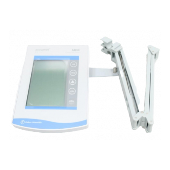
- Page 4 INTRODUCTION Thank you for selecting the Fisher Scientific Accumet AB 30 bench-top meter. This instruction manual describes the operation of the meter. The state-of-art meter that you have purchased is easy to operate and will guide you through the various functions by displaying easy to understand prompts.
- Page 5 UNPACKING THE METER The following is a listing of what you should have received with your Accumet AB 30 conductivity meter. Meter with kit includes Meter Power supply Electrode arm support bracket Electrode arm ATC probe Manual and literature Note that this meter does not include a conductivity cell RS 232 communication cable Meter only includes Meter...
-
Page 6: Getting Started
GETTING STARTED 3.1 Connectors 1. Review the layout and arrangement of the rear connector panel. - Page 7 2. Connect the electrode arm to the base. 3. Connect the power cable to the connector cable to the rear connector panel power jack and to a power source.
-
Page 8: Using The Meter
USING THE METER 4.1 Conductivity Probes This meter allows you to use both 2-cell and 4-cell conductivity probes. F F F F DO NOT connect both probes together. Remove the protective cover from the end of the probe. Prior to use, soak the probe in distilled or deionized water for 10 minutes. - Page 9 2. Rinse the conductivity probe sensing elements with distilled or deionized water between samples. For long term storage, the probes can be stored dry or in distilled water. F F F F Note that the cell constant may change slightly due to storage or use, and it must be re-evaluated with the use of standard conductivity solution (standardization) prior to use.
-
Page 10: Display/ Keys
4.2 Display/ Keys Overview of the meter screen display and function key layout. Press std key to initiate standardization from measure mode. Or press std key at the Standardize mode to confirm the standardization and return to Measure mode. Press setup key to access setup for configuration of meter setting. -
Page 11: Screen Display
4.3 Screen Display Familiarize yourself with the layout of the digital screen display. -
Page 12: Conductivity Operation
CONDUCTIVITY OPERATION 5.1 Using Setup Setup allows you to set the operating parameters of the meter to meet your requirements. There are two ways to access setup, and the parameters that you can set will be different depending on how you accessed setup. -
Page 13: Using Setup From The Measure Screen
5.1.1 Using setup from the measure screen If you are currently viewing the Setup screen, setup is in essence a scroll button which allows you to access, view, and change a variety of operating parameters. While in setup, you may: Press std to exit from setup to measure screen without making change. - Page 14 Program 10: Program 1: Select Temperature View Cell Constant Coefficient (5.2%) - View the calculated cell constant stored in memory. A series of - Select the temperature dashes Ò- - -Ó appears if there is coefficient from 2.0%, 5.2%, no cell constant in memory. C ell Constant COEFF 0.0% or 1.5%.
-
Page 15: Program 1: View The Calculated Cell Constant
5.1.2 Program 1: View the calculated cell constant 1. Press setup to view the calculated cell constant stored in memory. 2. If there is no cell constant in memory, a series of dashes Ò---Ò will appear. Press enter to accept the displayed cell constant and return to the Measure screen, 3. -
Page 16: Program 2: View The Standardized Value
5.1.3 Program 2: View the standardized value 1. If the meter is not standardized , a series of dashes will appear , Ò---Ò 2. Press enter to accept the displayed last-standardized value and return to measure screen or press setup again to go to the next page. -
Page 17: Program 3: Select The Conductivity Mode
5.1.4 Program 3: Select the conductivity mode Press enter to accept this choice of measuring conductivity and return to the measure screen or press setup again to go to the next page. µS 5.1.5 Program 4: Select resistivity mode Press enter to accept this choice of measuring resistivity and return to the measure screen or press setup again to go to the next page. -
Page 18: Program 6: Select The Cell Constant (1.00)
5.1.7 Program 6: Select the cell constant (1.00) Press enter to accept this choice of nominal cell constant and return to measure screen or press setup again to go to next page. C ell C ons tant 5.1.8 Program 7: Select the cell constant (10.00) Press enter to accept this choice of nominal cell constant and return to measure screen or press setup again to go to next page. - Page 19 C ell C ons tant...
-
Page 20: Program 9: Select The Temperature Coefficient (2.0%)
5.1.10 Program 9: Select the temperature coefficient (2.0%) Press enter to accept this choice of temperature coefficient and return to measure screen or press setup again to go to next page. C OEFF 5.1.11 Program 10: Select the temperature coefficient (5.2%) Press enter to accept this choice of temperature coefficient and return to measure screen or press setup again to go to next... - Page 21 C OEFF...
-
Page 22: Program 12: Select The Temperature Coefficient (1.5%)
5.1.13 Program 12: Select the temperature coefficient (1.5%) Press enter to accept this choice of temperature coefficient and return to measure screen or press setup again to go to next page. C OEFF... -
Page 23: Program 13: Select The Tds Factor (0.40 Ð 1.00)
5.1.14 Program 13: Select the TDS Factor (0.40 Ð 1.00) Use the π key to adjust the TDS factor. Press enter to accept these adjusted values of TDS Factor and return to measure screen or press setup again to get to the next page. press to set value press to s elec t options... -
Page 24: Program 14: Temperature Unit Selection (¡C)
5.1.15 Program 14: Temperature unit selection (¡C) Press enter to accept the ¡C and return to measure screen or press setup again to go to the ¡F selection page. pres s to sele ct options se t up pres s ent e r to ac cept sele c t... -
Page 25: Program 16: Enable The Stable Icon
5.1.17 Program 16: Enable the STABLE icon Press enter to enable (ON) the STABLE and return to measure screen or press setup again to disable (OFF) the STABLE setup page. ST ABL E press to select options setup press to accept enter... -
Page 26: Program 17: Disable The Stable Icon
5.1.18 Program 17: Disable the STABLE icon Press enter to disable (OFF) the STABLE and return to measure screen or press setup again to go to the next setup page. ST ABL E press to select options setup press to accept enter... - Page 27 5.1.19 Program 18: Clear the user standardization Press enter to select to clear the calibration and return to measure screen or press setup again to skip the option. µS clear press to select options setup press to accept enter F F F F Depends on the measure mode you are in, this setup page clears only the particular mode calibrated value.
-
Page 28: Standardization
STANDARDIZATION 6.1 Using Setup Conductivity probes are generally identified as having characteristic cell constant, 0.1, 1.0 or 10.0 which reflects their physical geometry and their range of application. However, these are typically nominal cell constants. The actual cell may vary somewhat from the nominal values, and therefore the actual cell constant must be calculated using a solution with a known conductivity value. - Page 29 After adjusted std solution value (which will be displayed at the upper display), press std to initiate the standardization and on successful completion meter returns to measurement mode. S TA BLE press to s ele ct options se tup press to standardize st d STD Solution F F F F...
- Page 30 Resistivity/ TDS Standardization Follow the same procedure as explained in the conductivity calibration. Note: There are separate standardization provided for conductivity, TDS and resistivity. And also in each mode there are separate calibration for 2 cell and 4 cell. So altogether 6 independent calibration are available and each acts independently.
-
Page 31: Measurement
MEASUREMENT 7.1 Conductivity Measurement 1. Immerse the electrode into the sample solution. Stir moderately. F F F F Make sure that the meter is in the Measure mode. If you are using the 2-cell electrode, and separate temperature probe is NOT available then meter takes 25¡C as default temperature. - Page 32 ST ABL E press to sele ct options set up press to standardize STD Solution...
-
Page 33: Resistivity Measurement
7.2 Resistivity Measurement Unit will be in ohm, kohm or Mohm. 1. Immerse the electrode into the sample solution. Stir moderately. F F F F Make sure that the meter is in the Measure mode. If you are using the 2-cell electrode, and separate temperature probe is NOT available then meter takes 25¡C as default temperature. -
Page 34: Tds Measurement
7.3 TDS Measurement TDS readings will be in ppm unit. TDS factor can be selected from the setup menu. (0.40 to 1.0). Default: 0.66. 1. Immerse the electrode into the sample solution. Stir moderately. F F F F Make sure that the meter is in the Measure mode. If you are using the 2-cell electrode, and separate temperature probe is NOT available then meter takes 25¡C as default temperature. -
Page 35: Temperature Measurement
Temperature Measurement If the temperature probe is not connected then meter displays 25.0¡C default icon on the secondary display. If the temperature probe is connected then meter senses the actual temperature and displays with ATC icon. F F F F 4-cell conductivity probe has a built-in temperature sensor. -
Page 36: Conductivity Operation
CONDUCTIVITY OPERATION 8.1 Replatinization Replatinization is the process of replacing the replacing the platinum on the surfaces of the 2-cell conductivity probes that may flake or wear off over time. The platinum on the surface of the probe is used to increase the measuring surface area, resulting in decreased population error. -
Page 37: Conductivity Theory
CONDUCTIVITY THEORY Conductance is a metric associated with the ability o primarily aqueous solutions to carry an electrical current, I, between two metallic electrodes when a voltage E is connected to them. Though water itself is a rather poor conductor of electricity, the presence of ions in the water increases its conductance... - Page 38 (µS/ cm) or milli-Siemens per cm (mS/ cm). The accumet Basic AB30 meter automatically converts conductivity readings from micro or milli Siemens to other derived units that are widely used. These are ppm TDS (total dissolved solids), and Resistivity (ohm*cm).
- Page 39 Conductivity Measurement Accumet conductivity probes consist of glass or epoxy bodies in which platinum or platinised sensing elements and are designated two-cell electrode has two such sensing elements and are designated two-cell electrodes. The previous discussion has focused on this type of electrode. Four cell electrodes are also available, and the theory and application of these are in a separate section.
- Page 40 The four-cell electrode Traditionally, conductivity measurements were made with a Òtwo cellÓ electrode. This electrode used two metallic sensors, an anode and a cathode to which ions migrated. Under the influence of DC current the electrodes quickly became polarized. In this situation, molecules formed at the electrode surfaces and ions migrating to the area collect around the respective anode or cathode and actually screen it from other ions.
-
Page 41: Cleaning
CLEANING This meter requires no regular maintenance, but it is recommended to occasionally wipe down the front with a damp cloth from time to time. METER SPECIFICATIONS Description AB30 Display Custom LCD Screen Size 3Ó X 4.25Ó Measurement Display Height _Ó... - Page 42 TDS Mode 0 to 99999 ppm 0.001 for 0.000 Ð 9.999 0.01 for 10.00 Ð 99.99 Resolution 0.1 for 100.0 Ð 999.9 1 for 1000 Ð 99999 Accuracy 0.5% of the reading Others Cell constants range 0.1, 1.0, 10.0 Temperature coefficients 0.0%, 1.5%, 2.0%, 5.2% TDS factor 0.40 Ð...
- Page 43 WARRANTY The Fisher Scientific Company (ÒFisherÓ) warrants to the direct purchaser that the Accumet meters and Accumet, AccuTupH, AccuFet, AccupHast, and Microprobe electrodes will be free from defects in material or workmanship for a specified warranty period. During that period, Fisher will repair or replace the product or provide credit, at its sole option, upon prompt notification and compliance with its instructions.
- Page 44 Fisher Scientific supplied power supply must be used. Use of a power supply that is not approved by Fisher Scientific may cause safety hazards and/or cause unit to exceed EMC limits and/or damage unit. When using his meter with a computer or printer, a shielded RS232 cable must be used to meet or exceed FCC regulations, and comply with CE Mark requirements.
- Page 45 REPLACEMENT PARTS 14.1 Replacement parts Description Fisher Catalog Number AccuFlex electrode support arm 13-637-671 Electrode support bracket 13-637-671A Power Supplies: 115V, US plug 13-636-100 230V, UK plug 13-636-101 230V, Europe plug 13-636-102 OperatorÕs Manual 13-636-AB15M ATC probe 13-620-19 To place an order, call 1-800/ 766-7000 For technical Support, call 1-800/ 943-2006...
- Page 46 68X295901 Rev. 2 0903...
Need help?
Do you have a question about the Accumet Basic AB30 and is the answer not in the manual?
Questions and answers