Table of Contents
Advertisement
pH-Measure
Last Standardization :7 Mar 2004 / 4:06:37 PM
Buffer Group :USA
> Touch standardize icon to access standardiztion mode
Show Graph
Sample ID :
User ID
: Default
Auto Buffer : ON
Auto Read : OFF
12.000
XL1 5
---
Temp. : 25.5 C (ATC)
USER Manual
mV
Slope
Offset
Channel 1
STABLE
: -295.7
: 102.8%
: -32.4 mV
Standardize
Measure
Mode
Setup
Print
Log Data
Profile
Home
Logoff
?
Help
Advertisement
Table of Contents

Subscribe to Our Youtube Channel
Related Manuals for Fisher Scientific XL15


Summary of Contents for Fisher Scientific XL15
- Page 1 pH-Measure Channel 1 Standardize 12.000 Measure XL1 5 STABLE Mode Last Standardization :7 Mar 2004 / 4:06:37 PM Buffer Group :USA Setup > Touch standardize icon to access standardiztion mode Print Show Graph Log Data Profile Sample ID : Temp. : 25.5 C (ATC) USER Manual Home User ID...
- Page 2 XL1 5 USER Manual...
- Page 3 Table of Contents Introduction....................3 Unpacking the Meter ..................4 Specifications ....................5 Getting Started CONNECTORS.......................6 pH ELECTRODES ......................7-8 Using the Meter TOUCH SCREEN OPERATIONS ..................9-10 Using the STYLUS......................11 Setting TIME and DATE....................12 ON-SCREEN KEYBOARD ....................13 EXPANSION CARD ......................14 Connecting to the INTERNET..................15 Choosing a CHANNEL ....................16 BUTTON FUNCTIONS .
-
Page 4: Introduction
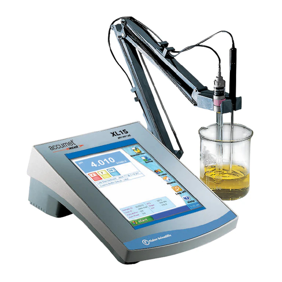
Thank you for selecting a Fisher Scientific accumet pH meter. This manual describes the operation of the accumet XL15 meter. The state-of-the art meter that you have purchased runs on a Windows CE platform and has a similar framework of a pocket PC ( or "Palm Pilot"). -
Page 5: Unpacking The Meter
Unpacking the Meter The following is a listing of what you should have received with your new accumet XL15 pH/mV meter. Meter with kit includes meter power supply electrode arm support bracket electrode arm electrode (13-620-130) ATC probe (13-620-19) manual and literature... -
Page 6: Specifications
Specifications Display 640x480 digit LCD screen size 4 1/2” x 6” menu options extensive help screens extensive configurable display keypad controls context specific touchscreen Memory 1000 data pts internal diagnostics programmable data storage store on stable, time, manual programmable data output output on stable, time, manual print interval 1 to 86400 sec... -
Page 7: Connectors
CONNECTORS Getting Started Review the layout and arrangement of the rear connector panel. accuFET pH electrode Stylus (Channel 3) Power Automatic Temperature RJ 45 Compensation (ATC) USB-A, Ver 1.1 Reference pin jack Ver 1.1 BNC input connector twin port* (Channel 1) POWER ATC1 REF1... -
Page 8: Ph Electrodes
pH ELECTRODES Getting Started This meter allows you to use two types of pH electrodes: the conventional glass pH electrode and the AccuFET field effect transistor (FET) pH electrode. Carefully remove the protective cover from the end of the electrode. Before first using your glass pH electrode, or whenever the electrode is dry, soak it 2-4 hours in an electrode storage... -
Page 9: Ph Electrodes
pH ELECTRODES Getting Started Rinse and blot-dry (don't wipe) elec- trodes between each measurement. Rinse electrodes with distilled or deionized water, or a portion of the next solution to be measured. Between measurements, store con- ventional pH electrodes in electrode storage solution, pH 4 buffer, or KCl solution. -
Page 10: Touch Screen Operations
Using the Meter When the meter is turned on it first goes though self test, displays the FISHER Catalog cover, briefly displays the desktop screen (Home) before loading the XL15 program which results in the display of the measurement screen. -
Page 11: Touch Screen Operations
Touch any icon to access the functions of the meter. Your XL15 meter also includes a stylus that you can use to tap on your screen. The stylus easily stores inside the back panel of the meter. - Page 12 Using the STYLUS Using the Meter Your XL15 Meter comes with a stylus that you should use to tap on your screen. The stylus easily stores inside the back panel of the meter. You can perform two basic actions using the stylus: Lightly touch the screen to select or open an item.
-
Page 13: Setting Time And Date
Setting TIME and DATE Using the Meter Setting the Time 1. From the HOME screen tap the bottom left of the screen to access the Start menu. Tap Start > Settings > Control Panel. This launches the Control Panel screen. 2. -
Page 14: On-Screen Keyboard
ON-SCREEN KEYBOARD Using the Meter Using the On-Screen Keyboard Use the stylus to tap letters, numbers, and symbols on the on-screen keyboard to enter typed text directly onto the screen. 1. From any application, screen tap the bottom right of the screen to access the input panel. -
Page 15: Expansion Card
XL15 meter Installing an Expansion Card To install a Secure Digital (SD) card into an expansion slot on the XL15 meter: 1. Locate the slot on the top of XL15 meter. 2. Remove the protective plastic card. -
Page 16: Connecting To The Internet
With Pocket Internet Explorer and a connection to the Internet, you can view Web sites on your XL15 meter by typing an address or Universal Resource Locator (URL) in the Address bar. Web sites that use HTML 4.0, DHTML, animated GIF images, and Java applets may not work correctly in Pocket Internet Explorer without additional software. -
Page 17: Choosing A Channel
Choosing a CHANNEL Using the Meter The XL15 is a multi-channel meter. With this meter you can switch from channel 1 to channel 3. You cannot view both channels at the same time. The setup parameters for each screen are independent from one another. -
Page 18: Button Functions
BUTTON FUNCTIONS Using the Meter The touch screen of your XL15 bench meter has “buttons” along the right side of the screen that are common to many of the screens. The following indicates the function of these common buttons. The Standardize button accesses the standardization screen from the various measure modes and initiates standardization of the meter once the standardization screen is accessed. -
Page 19: Button Functions
BUTTON FUNCTIONS Using the Meter The rel mV button returns the meter into the relative millivolt mode when in the Touch set to set relative mV or Touch default to accept the default value absolute mV mode. When this mode is (0 mV) rel mV activated, a window will appear asking... - Page 20 pH SETUP SCREEN pH Setup The pH Setup screen present many options to control the operating parameters of the meter. The meter is factory set with regard to these options, and is ready for use under most circumstances (see appendix page 59 for default settings). The operating parame- ters of the pH mode can be set and controlled from the pH setup screen.
-
Page 21: Access Ph Setup
Access pH SETUP pH Setup There is one way to access the pH Setup screen. 1. Make sure meter is in pH Measure mode. Touch pH on the mode screen to access the pH mode Measure screen 2. Touch Setup option on the pH Measure screen pH-Measure Channel 1 Standardize... -
Page 22: Set Sample Id
Set SAMPLE ID# pH Setup Whenever this option is active, each time you touch Print or Log Data on the pH Measure screen, the pH (or pH FET ) value along with date/time/channel and the sample ID will be sent to data storage. You can manually enter an alphanumeric identification number of 10 characters for any sample or you can have the meter sequentially number your samples beginning at the number of your choice. -
Page 23: Select Buffer Group
Select BUFFER GROUP pH Setup This setup option allows you to select from 3 different buffer groups, for auto buffer recognition. Or you can create a custom group of buffers for auto buffer recognition by touching custom. The 3 existing buffer groups are : 2.00 4.00 7.00 10.00 12.00... -
Page 24: Select Buffer Recognition
Select BUFFER RECOGNITION pH Setup This option allows you to select Automatic buffer recognition or manual buffer recog- nition when standardizing. With the automatic buffer recognition activated, the meter will automatically recognize the buffers from the chosen buffer group and accept them when the meter recognizes the reading as stable. -
Page 25: Select Auto Read Mode
Select AUTO READ MODE pH Setup You can use this meter when the Auto Read function is active or when it is inactive. When the Auto Read function is active, the meter will lock onto a reading when the meter recognizes it as stable. The meter will not deviate from this reading until Measure is touched. -
Page 26: Set Ph Stability Criteria
Set pH STABILITY CRITERIA System Setup This setup screen allows you to determine how quickly the meter will respond to electrode drift. There are 3 speed settings: fast, medium and slow To set pH Stability Criteria 1. Touch FAST, MEDIUM, SLOW to choose the desired stability criteria. pH Stability Criteria FAST MEDIUM... -
Page 27: Set Default Temperature
Set DEFAULT TEMPERATURE pH Setup It is a well known fact that pH is a temperature dependent measurement. The factory default setting is 25°C. If you are taking the pH of a solution that is not 25°C and you are not using an Automatic Temperature Compensation (ATC) probe, then you should enter the temperature value of that solution in order to get the correct pH value. -
Page 28: Set Isopotential Point
Set ISOPOTENTIAL POINT pH Setup The isopotential point is the millivolt reading for an electrode at which temperature has no effect on the measurement. pH electrodes are constructed so that the isopo- tential point is theoretically zero millivolts. This is very close to a pH of 7. Most pH electrodes do not achieve this value precisely. -
Page 29: Set Alarm Limits
Set ALARM LIMITS pH Setup This option allows you to set alarm limits for the pH measuring mode. If the pH value of the measurement is outside of the boundaries set by the minimum and maximum limits, a visual warning will appear to let you know that your sample measurement was outside of the set limits. -
Page 30: Set Print Criteria
Set PRINT CRITERIA pH Setup This screen allows you to select which criteria are printed with the measurement when you print the data or send it to a computer. The status of the current print criteria is dis- played on the screen. The criteria option is active if ON appears to the right of the option. It is inactive if OFF appears to the right of the option. -
Page 31: Set Data Storage Criteria
Set DATA STORAGE CRITERIA pH Setup This screen allows you to select which criteria are stored in the data logger with the measurement when you store the data .The status of the current data storage criteria is displayed on the screen. The criteria option is active if ON appears to the right of the option. - Page 32 Set DISPLAY CRITERIA pH Setup This screen allows you to choose what information you would like to be displayed on the pH Measure screen, particularly the information contained in the data box at the bottom of the Measurement screen. The status of the current display criteria is dis- played on the screen.
-
Page 33: View Stored Data
View STORED DATA pH Setup The XL15 has a memory capacity to store up to 1000 data points. The View Stored Data screen allows you to sort and look at specific data points stored in the meter based on the meters memory capacity. The stored data can be sorted by any of the parameters available in the screen header. -
Page 34: View Stored Data
View STORED DATA pH Setup Reading Operator Date / Time / Channel Sample Id Temperature Last Stan 7.00 Default 1 Februa... 25.0 C 8.53 Default 1 Februa... 25.0 C 8.85 Default 1 Februa... 25.0 C 9.05 Default 1 Februa... 25.0 C 9.34 Default 1 Februa... - Page 35 mV SETUP SCREEN mV Setup The mV Setup screen present many options to control the operating parameters of the meter. The meter is factory set with regard to these options, and is ready for use under most circumstances (see appendix page 59 for default settings). The operating parameters of the mV mode can be set and controlled from the mV setup screen.
-
Page 36: Access Mv Setup
Access mV SETUP mV Setup There is one way to access the mV Setup screen. 1. Make sure meter is in mV Measure mode. Touch mV on the main screen to access the mV mode Measure screen 2. Touch Setup option on the mV Measure screen abs mV Channel 1 376.2... -
Page 37: Set Sample Id
Set SAMPLE ID # mV Setup Whenever this option is active, each time you touch Print or Log Data on the mV Measure screen, the mV value along with date/time/channel and the sample ID will be sent to data storage. You can manually enter an alphanumeric identification number of 10 characters for any sample or you can have the meter sequentially number your samples beginning at the number of your choice. -
Page 38: Set Alarm Limits
Set ALARM LIMITS mV Setup This option allows you to set alarm limits for the mV measuring mode. If the mV value of the measurement is outside of the boundaries set by the minimum and maximum limits, a visual warning will appear to let you know that your sample measurement was outside of the set limits. - Page 39 Set PRINT CRITERIA mV Setup This screen allows you to select which criteria are printed with the measurement when you print the data or send it to a computer. The status of the current print criteria is dis- played on the screen. The criteria option is active if ON appears to the right of the option. It is inactive if OFF appears to the right of the option.
-
Page 40: Set Data Storage Criteria
Set DATA STORAGE CRITERIA mV Setup This screen allows you to select which criteria are stored in the data logger with the measurement when you store the data .The status of the current data storage criteria is displayed on the screen. The criteria option is active if ON appears to the right of the option. -
Page 41: Set Display Criteria
Set DISPLAY CRITERIA mV Setup This screen allows you to choose what information you would like to be displayed on the mV Measure screen, particularly the information contained in the data box at the bottom of the Measurement screen. The status of the current display criteria is dis- played on the screen. -
Page 42: View Stored Data
View STORED DATA mV Setup The XL15 has a memory capacity to store up to 1000 data points. The View Stored Data screen allows you to sort and look at specific data points stored in the meter based on the meters memory capacity. The stored data can be sorted by any of the parameters available in the screen header. -
Page 43: View Stored Data
View STORED DATA mV Setup Reading Operator Date / Time / Channel Sample Id Meter Model Serial No. -400.5 Default 1 Jan 20... -400.5 Default 1 Jan 20... -399.9 Default 1 Jan 20... -376.2 Default 1 Jan 20... -376.2 Default 1 Jan 20... - Page 44 pH Operation In this mode, you will able to measure the pH of a wide variety of samples. Before meas- uring pH, you will need to standardize the meter using buffers with known pH values. It is good practice to standardize the meter frequently using a minimum of two buffers. Using two buffers allows the meter to calculate and display an actual slope for the electrode, and therefore produce more accurate measurements.
-
Page 45: Standardizing
STANDARDIZING pH Operation pH-Standardize Channel 1 12.000 Confirm STABLE Clear 2.00 4.00 7.00 10.00 12.00 Cancel Last Standardization :7 Mar 2004 / 10:06:37 PM Buffer Group :USA Temp Std > Touch "Confirm" to Standardize the buffer > Touch "Clear" to clear the previous Standardization >... -
Page 46: Standardizing
STANDARDIZING pH Operation To Standardize the meter with Auto Buffer Recognition 1. Touch Standardize on the pH measure screen to access the standardized screen. Standardize 2. If the screen says “Not standardized” proceed to step 4. 3. Touch Clear to delete all previous standardization values. 4. - Page 47 STANDARDIZING pH Operation pH-Standardize Channel 1 12.000 Confirm STABLE Clear Cancel Last Standardization :8 Mar 2004 / 4:06:37 PM Buffer Group :CUSTOM Temp Std > Touch "Confirm" to Standardize the buffer > Touch "Clear" to clear the previous Standardization > Touch "Cancel" to return to the Measurement >...
- Page 48 STANDARDIZING pH Operation To standardize the meter with Manual Buffer Recognition 1. Touch Standardize on the pH measure screen to access the standardized screen. 2. If the screen says “Not standardized” proceed to step 4. 3. Touch Clear to delete all previous standardization values. 4.
- Page 49 TEMPERATURE STANDARDIZATION pH Operation To Standardize Temperature of the Meter 1. Touch Standardize on the pH measure screen to access the standardized screen. 2. Make sure ATC probe is attached to meter. 3. Immerse your ATC probe into a solution of known temperature, such as a tempera- ture bath, for a few minutes while temperature stabilizes.
-
Page 50: Ph Measurement
pH MEASUREMENTS pH Operation pH-Measure Channel 1 Standardize 4.000 Measure STABLE 7.00 10.00 12.00 Mode Last Standardization :7 Mar 2004 / 4:06:37 PM Buffer Group :USA Setup > Touch measure icon to measure sample > Touch standardize icon to access standardiztion mode Print Show Graph Log Data... -
Page 51: Ph Measurement
pH MEASUREMENTS pH Operation The measure screen provides readout of the current sample measurement. You can use this meter when the Auto Read function is active or when it is inactive. When the auto read function is active, the meter will lock onto a reading when the meter recognizes it as stable. - Page 52 mV Operation This mode is used to measure oxidation/ reduction potential (ORP/redox), perform titration and to verify the function of the meter.The mV measure function allows you to continuously monitor the mV potential of the electrodes in use. This can be done in either absolute or relative mV.
-
Page 53: Mv Measurement
mV MEASUREMENT mV Operation In the mV mode, you will be able to make measurements in either absolute or relative millivolts, access the mV Setup screens and print your results to a printer or a computer. Connect the electrodes you will be using to the meter. See page 6 for details. Absolute mV Measurements 1. -
Page 54: Mv Measurement
mV MEASUREMENT mV Operation abs mV Channel 1 rel mV STABLE Mode Setup > Touch rel mV icon for relative mV reading Print Sys.Setup Show Graph Log Data Profile Profile Sample ID : Temp. : 25.5 C (ATC) Home pH (FET) Home User ID : Default... -
Page 55: Cleaning
Cleaning The touch screen should be kept as clean as possible to preserve optical properties. Attempt to keep the screen free of dirt, dust fingerprints, etc .Long term contact with abrasive materials will scratch the surface, and impair image quality. To clean, use a damp nonabrasive cloth towel and any commercially available window cleaner. -
Page 56: Trouble Shooting
Trouble Shooting Your XL15 meter contains many error messages to provide aid should trouble occur with a measurement or meter operation (touch pad and input errors). The messages are accompanied by a brief description of the error, and in some cases advice on how to correct it. -
Page 57: Warranty
Warranty pH Meter and Electrode Warranty Statement The Fisher Scientific Company (“Fisher”) warrants to the direct purchaser that the accumet meters and Accumet, AccuTupH, AccuFET, AccupHast, and Microprobe electrodes will be free from defects in material or workmanship for a specified warranty period. During that period, Fisher will repair or replace the product or provide credit, at its sole option, upon prompt notification and compliance with its instructions. -
Page 58: Compliance
Fisher-supplied power supply must be used. Use of a power sup- ply that is not approved by Fisher Scientific may cause safety hazards and/or cause unit to exceed EMC limits and/or damage unit. When using this meter with a com- puter or printer, a shielded RS232 cable must be used to meet or exceed FCC regu- lations, and comply with CE Mark requirements. -
Page 59: Determining Isopotential Points Experimentally
Determining ISOPOTENTIAL POINTS EXPERIMENTALLY Appendix The isopotential point of an electrode system is the point at which electrode potential is unaffected by a change in temperature. The coordinates of this point would be reported as (pX , Eis ). For an ideal system, this point would be coincident with the system’s Zero Potential Point (pX In practical systems, however, this coincidence rarely occurs, and for some systems, there is no true Isopotential Point but a general Isopotential area. -
Page 60: Factory Default Settings
Factory DEFAULT SETTINGS Appendix The following is the list of factory default settings for the XL15 meter. You can reset your meter to the factory default settings by accessing the Reset to Factory Defaults from the System Setup screen Screen... -
Page 61: Ph Theory
pH THEORY Appendix Since its introduction by the Danish chemist Sorensen in 1909, pH measurement has become one of the most commonly used and important measurements in both laboratory and industrial settings. pH measurement and control is vital to a wide array of endeavors including municipal and industrial wastewater treatment, and textile, pharmaceutical, food, and petroleum production. - Page 62 pH THEORY Appendix At 25°C in pure water, the concentration of hydronium ions is extremely small, 1 x 10 Moles/liter, and balanced by an equal concentration of hydroxyl ions. The equilibrium constant, Kw of water is the product of the hydronium ion and hydroxyl ion concentrations: –...
- Page 63 pH THEORY Appendix pH Measurement The pH value of a sample can be determined in several ways. These include the use of organic dyes which change color in certain pH ranges. The dyes can be added directly to the solution or impregnated onto paper which may be dipped into the solution. At best, these "colorimetric"...
- Page 64 pH THEORY Appendix Temperature 4.01 6.86 9.18 4.003 6.984 9.464 3.998 6.923 9.332 4.002 6.881 9.225 4.008 6.865 9.180 4.015 6.853 9.139 4.035 6.838 9.068 4.060 6.833 9.011 pH Electrodes The electrode system consists of two half cells: a pH indicating electrode, which is primarily responsive to the acidity (the hydronium ion concentration-tion) of a solution, and a reference electrode, which provides a constant voltage and completes the electrical circuit.
-
Page 65: Ph Theory
FET. All of Fisher Scientific's AB, AR and XL meters are capable of using this type of electrode by direct connection (except AB30). -
Page 66: Replacement Parts
Replacement Parts Replacement Parts Description Fisher Catalog Number Accumet pH combination electrode, single junction, Ag/AgCl reference, glass body, BNC connector ......13-620-285 ATC Probe .
Need help?
Do you have a question about the XL15 and is the answer not in the manual?
Questions and answers