
Related Manuals for Grundfos PACOpaQ


Summary of Contents for Grundfos PACOpaQ
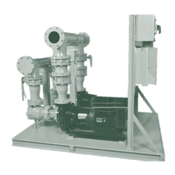
- Page 1 GRUNDFOS INSTRUCTIONS PACOpaQ™ HVAC Packaged Systems Installation and Operating Instructions...
-
Page 2: Table Of Contents
Pump Troubleshooting 2.11 Technical documents Symptom 2.12 Limitation of liability Possible causes 2.13 This company is an equal opportunity Grundfos CUE Variable Frequency Drive employer CUE introduction 2.14 Law and arbitration General description PACOpaQ system installation Applications General instructions References... -
Page 3: Symbols Used In This Document
17.5 Menu OPERATION 32.6 Digital inputs 17.6 Menu STATUS 32.7 Analog inputs 17.7 Menu INSTALLATION 32.8 Digital outputs (relay putputs) Setting by means of PC Tools E-products 32.9 Conductors Priority of setttings 32.10 USB port 19.1 Control without bus signal, local operating 32.11 Battery backup (UPS) mode... -
Page 4: Terms And Conditions
2. Terms and Conditions 2.5 Title and risk of loss 2.1 The contract Full risk of loss (including transportation delays and losses) shall pass to Buyer upon delivery, regardless of whether title has The Contract shall be comprised of the following terms, together passed to Buyer, transport is arranged or supervised by Seller, or with such terms and conditions as are set forth in Seller's written start-up is carried out under the direction or supervision of Seller. -
Page 5: Warranty
2.10 Warranty 2.11 Technical documents Seller warrants that the equipment or services supplied will be Technical documents furnished by Seller to Buyer, such as free from defects in material, and workmanship for a period of drawings, descriptions, designs and the like, shall be deemed 24 months from the date of initial operation of the equipment, or provided to Buyer on a confidential basis, shall remain Seller's 30 months from the date of shipment, whichever shall first... -
Page 6: Pacopaq System Installation
3. PACOpaQ Installation 3.1 General instructions Important notice: Carefully inspect this equipment for damage, and missing pieces. If the shipment has been damaged or there are missing pieces, have the carrier note the condition on the receipt. Also, check as soon as possible for any concealed damage. -
Page 7: Assembly Of Packaged Sections (If Applicable)
gaskets required for re-assembly are supplied. 3.6 Assembly of packaged sections Final package system connections hardware by (if applicable): others. 1. Refer to specific installation documents or 11. Ensure alignment of pipe end connections drawings for the package system. between sections. Connections must be square. Install the required bolts for each of the fitting 2. -
Page 8: Pump Identification
3.4 Location codes of good practice. • Locate the pump as close to the suction supply as possible. Use the shortest and most direct suction piping practical. Warning Refer to 3.9 Suction (inlet) piping. The use of this product requires experience with •... -
Page 9: Securing Base Plate
4.9 Suction (inlet) piping The sizing and installation of suction piping is particularly Grout Base plate important. It must be selected and installed in a manner that Finished minimizes pressure loss and permits sufficient liquid flow into the grouting pump during starting and operation. Many NPSH problems can .75 to 1.25 be traced directly to improper design of suction piping systems. -
Page 10: Discharge (Outlet) Piping
4.13 Mechanical seals All PACO Type L pumps that are equipped with mechanical seals are matched to conditions for which the pump was sold. Observe the following precautions to avoid seal damage and obtain maximum seal life: • Do not exceed temperature or pressure limitations for the mechanical seal used. -
Page 11: Coupling Alignment (Lf)
4.14 Coupling alignment (LF) 5. Installation-electrical • The following anchoring and alignment procedure is typical Warning and, if performed with care, should result in a smooth running, Use only qualified electricians for electrical trouble-free installation. installation and maintenance. • If the pump and motor were shipped mounted on the pump Refer to manuals provided with electrical base as an assembly, remove the coupling guard. -
Page 12: Pump Operation
6. Operation 6.3 Motor rotation 5.1 Priming Never check driver rotation unless pump and driver couplings are disconnected and physically • The PACO Type L pump is not self-priming, and must be Caution separated. Failure to follow this instruction can completely primed (filled with liquid) before starting. -
Page 13: Voltage Regulation
6.5 Voltage regulation 7. Maintenance The motor will operate satisfactorily under the following Warning conditions for voltage and frequency variation, but not necessarily Do not attempt any maintenance, inspection, in accordance with the standards established for operation under repair or cleaning in the vicinity of rotating rated conditions: equipment. -
Page 14: Pump Lubrication
7.2 Pump lubrication List of acceptable Lube oils • PACO Type LF pumps on horizontal bearing frames have bearing that may be sealed for life (requiring no lubrication), Lubricant Manufacturer Bearing oil brand name regreasable or oil lubricated. Aral Oil CMU Aral Refining Co. -
Page 15: Disassembly Of Pumps
7.3 Disassembly of pumps 7.4 Seal replacement (LCS) 1. Complete preparations noted. Warning 2. Remove coupling guard (34F). Depending on the product being pumped, the 3. Remove coupling bolts (8E). Pry apart the coupling halves pump should be washed down before any work is (23D), remove keys (12B) and set aside. -
Page 16: Ordering Parts
Coupling guard must be reinstalled and in place prior to operation. 7.7 Ordering parts Grundfos Pumps has over 90 years of experience in the design, manufacture, and application of centrifugal pumps and pumping systems. Grundfos's commitment to state-of-the-art pump design and quality manufacturing assures maximum user benefits with optimum equipment life at lower cost. -
Page 17: Type Lf, Cross Section And Parts List
7.8 Type LF, cross section and parts list ITEM NO PART NAME ITEM NO PART NAME ITEM NO PART NAME Casing *10A Washer, Packing 16L Plug, Seal Chamber Backplate Washer, Impeller Bearing, Inboard Enclosed Impeller Gasket, Casing Bearing, Outboard Case Wear Ring Gasket, Backplate Bearing Frame Stud, Packing... -
Page 18: Type Lc, Cross Section And Parts List
7.9 Type LC, cross section and parts list ITEM NO PART NAME ITEM NO PART NAME Casing Gasket, backplate Backplate Impeller *13A Packing Front case wear ring Slinger Rear case wear ring Mechanical seal Shaft sleeve Plug, drain Lantern ring Plug, stuffing box Packing gland Bracket... -
Page 19: Type Lcv, Cross Section And Parts List
7.10 Type LCV, cross section and parts list ITEM NO PART NAME ITEM NO PART NAME Volute Impeller washer Hand hole cover (not shown) Backplate Slinger Impeller Single mechanical seal assembly Suction cover wear ring Stand Impeller wear ring Pedestal bracket Sleeve Elbow with clean out port Impeller screw... -
Page 20: Type Lcs, Cross Section And Parts List
7.11 Type LCS, cross section and parts ITEM NO PART NAME ITEM NO PART NAME VOLUTE SEAL CAP O-RING SEAL CAP BASE RAIL IMPELLER MOTOR DECK CASE WEAR RING CAST IRON STAND BALANCE RING PUMP SUPPORT PUMP SHAFT MOTOR BRACKET VOLUTE SCREW SEAL CAP STUDS PUMP SHAFT SCREW... -
Page 21: Symptom
8. Trouble Shooting 8.1 Symptom Symptoms Cause Code Pump does not deliver any liquid at start-up. 1*2*3*4*5*6*7*8*9*10*11*14*16*17*22*23*24*34 Pump stops delivering liquid after start-up. 2*3*4*5*6*7*8*9*10*11*12*13*22*23*24*34 Pump overheats and/or ceases to deliver liquid. 1*3*9*10*11*21*22*27*29*30*31*33*34*40*41 Insufficient flow rate. 2*3*4*5*6*7*8*9*10*11*14*16*17*20*21*22*23*24*25*26*34 Excessive flow rate. 15*18*20*34 Discharge pressure is too high. -
Page 22: Grundfos Cue Variable Frequency Drive
Connected to a sensor or an external control signal, the CUE will quickly adapt the pump speed to the actual demand. 9.3 Applications The CUE series and Grundfos standard pumps are a supplement to the Grundfos E-pumps range with integrated variable frequency drive. -
Page 23: References
(PELV). Technical documentation is available on www.grundfos.com > 10.3.1 IT mains International website > WebCAPS. If you have any questions, please contact the nearest Grundfos Warning company or service workshop. Do not connect 380-500 V CUE variable frequency drives to mains supplies with a voltage between 10. -
Page 24: Identification
Grundfos.bk Page 7 Friday, July 30, 2010 10:10 PM 11. Identification 12.2 Transportation and unpacking The CUE must only be unpacked at the installation site to prevent 11.1 Nameplate damage during the transport to the site. The CUE can be identified by means of the nameplate. -
Page 25: Mounting
Grundfos.bk Page 8 Friday, July 30, 2010 10:10 PM 12.4 Mounting Instructions according to EN IEC 61800-5-1: • The CUE must be stationary, installed permanently and The user is responsible for mounting the CUE Caution connected permanently to the mains supply. - Page 26 Grundfos.bk Page 9 Friday, July 30, 2010 10:10 PM 13.2.2 Wiring diagram 2. Connect the ground conductor to terminal 95 (PE) and the mains conductors to the terminals 91 (L1), 92 (L2), 93 (L3) of The wires in the terminal box must be as short as possible.
- Page 27 Grundfos.bk Page 10 Friday, July 30, 2010 10:10 PM 13.2.4 Motor connection, enclosures A2 and A3 13.2.5 Enclosure A5 For information about enclosure, see table in section 16.1. For information about enclosure, see table in section 16.1. Mains connection The motor cable must be screened for the CUE to Caution meet EMC requirements.
- Page 28 Grundfos.bk Page 11 Friday, July 30, 2010 10:10 PM 13.2.6 Enclosures B1 and B2 13.2.7 Enclosures B3 and B4 For information about enclosure, see table in section 16.1. For information about enclosure, see table in section 16.1. Mains connection Mains connection...
- Page 29 13.2.9 Enclosures C3 and C4 The cable screen must be exposed and in Note For information about enclosure, see table in section 16.1. physical contact with the mounting plate and Mains connection clamp. 13.2.8 Enclosures C1 and C2 Check that mains voltage and frequency Caution For information about enclosure, see table in section 16.1.
-
Page 30: Connecting The Signal Terminals
Grundfos.bk Page 13 Friday, July 30, 2010 10:10 PM 13.3 Connecting the signal terminals Terminal Type Function As a precaution, signal cables must be separated +24 V out Supply to sensor Caution from other groups by reinforced insulation in +24 V out Additional supply their entire lengths. - Page 31 Grundfos.bk Page 14 Friday, July 30, 2010 10:10 PM 13.3.3 Access to signal terminals 13.3.4 Fitting the conductor All signal terminals are behind the terminal cover of the CUE 1. Remove the insulation at a length of 0.34 - 0.39 in (9-10 mm).
-
Page 32: Connecting The Signal Relays
Grundfos.bk Page 15 Friday, July 30, 2010 10:10 PM Access to signal relays The reference potential, GND, for RS-485 (Y) communication must be connected to terminal 61. The relay outputs are positioned as shown in figs 31 to 36. If more than one CUE unit is connected to a GENIbus network, the termination contact of the last CUE must be set to "ON"... -
Page 33: Connecting The Mcb 114 Sensor Input Module
Grundfos.bk Page 16 Friday, July 30, 2010 10:10 PM 13.5 Connecting the MCB 114 sensor input module The MCB 114 is an option offering additional analog inputs for the CUE. 13.5.1 Configuration of the MCB 114 The MCB 114 is equipped with three analog inputs for these sensors: •... -
Page 34: Emc-Correct Installation
Grundfos.bk Page 17 Friday, July 30, 2010 10:10 PM 13.6 EMC-correct installation Controller This section gives guidelines for good practice when installing the CUE. Follow these guidelines to meet EN 61800-3, first environment. • Use only motor and signal cables with a braided metal screen in applications without output filter. -
Page 35: Cue Operating Modes
Grundfos.bk Page 18 Friday, July 30, 2010 10:10 PM Example: Max. curve operation can for instance be used in Figures 42 and 43 show installations with and without filter and where to use screened and unscreened cable. connection with venting the pump during installation. -
Page 36: Controlled Operation (Closed Loop)
Grundfos.bk Page 19 Friday, July 30, 2010 10:10 PM 5.2 Controlled operation (closed loop) Constant temperature. Proportional The liquid differential temperature is kept pressure. constant, The differential independently of pressure is reduced the flow rate. at falling flow rate and increased at Δp... -
Page 37: Menu Overview
Grundfos.bk Page 20 Friday, July 30, 2010 10:10 PM 16. Menu overview START-UP GUIDE 0. GENERAL 1. OPERATION 1/16 2/16 0.24 3/16 8/16 4/16 9/16 1.5-1.9 5/16 10/16-14/16 Automatic or manual setting of the direction of rotation 6/16 15/16 1.10-1.14... - Page 38 2. STATUS 3. INSTALLATION 2.10 3.12 2.11 3.13 2.12 3.15 2.13 3.3A 3.16 2.14 3.17 2.15 3.18 2.16 3.19 2.17 3.20 3.21 3.22...
- Page 39 Grundfos.bk Page 22 Friday, July 30, 2010 10:10 PM 3.10 3.23 3.11 3.24...
-
Page 40: Setting By Means Of The Cotnrol Panel
Grundfos.bk Page 23 Friday, July 30, 2010 10:10 PM 17. Setting by means of the control panel The editing buttons of the control panel can be set to these values: 17.1 Control panel • Active • Not active. Warning When set to Not active (locked), the editing buttons do not The On/Off button on the control panel does not function. -
Page 41: Start-Up Guide
Grundfos.bk Page 24 Friday, July 30, 2010 10:10 PM 17.3 Start-up guide 17.3.4 Pump family (3/16) Check that equipment connected is ready for start-up, and that the CUE has been connected to Note power supply. Have nameplate data for motor, pump and CUE at hand. - Page 42 Grundfos.bk Page 25 Friday, July 30, 2010 10:10 PM 17.3.7 Max. motor current (6/16) The CUE will give an alarm if the control mode selected requires a sensor and no sensor has been installed. To continue the setting without a sensor, select "Open loop", and proceed. When a sensor has been connected, set the sensor and control mode in menu INSTALLATION.
- Page 43 Grundfos.bk Page 26 Friday, July 30, 2010 10:10 PM If the control mode selected is "Const. other value", or if the measuring range selected is "Other", the sensor must be set according to the next section, display 9A/16. 17.3.14 Another sensor connected to terminal 54 (9A/16) This display only appears when the control mode "Const.
-
Page 44: Operating Mode
Grundfos.bk Page 27 Friday, July 30, 2010 10:10 PM 17.3.18 General settings are completed (16/16) 17.3.20 Manual setting when the direction of rotation is not visible (13/16) It must be possible to observe the head or flow rate. • Press OK to make the pump ready for operation or start the pump in the operating mode Normal. -
Page 45: Menu General
Grundfos.bk Page 28 Friday, July 30, 2010 10:10 PM 17.4.2 Type code change (0.2) It is possible to interrupt the test and return to the previous display. This display is for service use only. The pressure will be shown during the test if a pressure sensor is 17.4.3 Copy of settings... - Page 46 Grundfos.bk Page 29 Friday, July 30, 2010 10:10 PM 17.5.2 Operating mode (1.2) Warning log (1.10-1.14) In case of a "warning", the last five warning indications will Set one of the following operating modes: appear in the warning log. "Warning log 1" shows the latest fault, •...
- Page 47 Grundfos.bk Page 30 Friday, July 30, 2010 10:10 PM 17.6.4 Measured value, sensor 1 (2.4) 17.6.9 Lubrication status of motor bearings (2.9) This display shows the actual value measured by sensor 1 This display shows how many times the user has given the connected to terminal 54.
- Page 48 Grundfos.bk Page 31 Friday, July 30, 2010 10:10 PM 17.7 Menu INSTALLATION 10.6.13 Temperature sensor 2 (2.13) 17.7.1 Control mode (3.1) This display is only shown if an MCB 114 sensor input module has been installed. Select one of the following control modes: This display shows the measuring point and the actual value •...
- Page 49 Grundfos.bk Page 32 Friday, July 30, 2010 10:10 PM The table below shows the suggested controller settings: 1. Heating systems are systems in which an increase in pump performance will result in a rise in temperature at the sensor. 2. Cooling systems are systems in which an increase in pump performance will result in a drop in temperature at the sensor.
- Page 50 If GENIbus is selected, the communication is set according to the Flow switch Grundfos GENIbus standard. FC and FC MC is for service purpose only. When this function is selected, the pump will be stopped when a connected flow switch detects low flow.
- Page 51 Grundfos.bk Page 34 Friday, July 30, 2010 10:10 PM Dry running When this function is selected, lack of inlet pressure or water On/off operation shortage can be detected. This requires the use of an accessory, Continuous operation such as: ®...
- Page 52 Grundfos.bk Page 35 Friday, July 30, 2010 10:10 PM A built-in low-flow detection function will automatically measure Diaphragm tank and store the power consumption at approx. 50 % and 85 % of the rated speed. Pressure sensor If Active is selected, proceed as follows: 1.
- Page 53 Grundfos.bk Page 36 Friday, July 30, 2010 10:10 PM 17.7.13 Sensor 2 (3.16) Setting of sensor 2 connected to an MCB 114 sensor input module. Select among the following values: • Sensor output signal: 0-20 mA 4-20 mA. • Unit of measurement of sensor:...
- Page 54 Grundfos.bk Page 37 Friday, July 30, 2010 10:10 PM 17.7.15 Operating range (3.18) The area between the min. and max. speed is the actual operating range of the pump. The operating range can be changed by the user within the pump-dependent speed range.
- Page 55 MCB 114: Special setup requirements differing from the settings available • D-end bearing via the CUE require the use of Grundfos PC Tool E-products. This • ND-end bearing again requires the assistance of a Grundfos service technician or engineer.
-
Page 56: Control With Bus Signal, Remote-Controlled
Grundfos.bk Page 39 Friday, July 30, 2010 10:10 PM 19. Priority of settings Terminal Type Function • Min. (min. curve) The On/Off button has the highest priority. In "off" • Max. (max. curve) condition, pump operation is not possible. • Ext. fault (external fault) The CUE can be controlled in various ways at the same time. - Page 57 Grundfos.bk Page 40 Friday, July 30, 2010 10:10 PM 20.3 GENIbus signal Closed loop In all other control modes, except proportional differential The CUE supports serial communication via an RS-485 input. pressure, the actual setpoint can be set externally within the...
-
Page 58: Warning And Alarm List
Grundfos.bk Page 41 Friday, July 30, 2010 10:10 PM 22. Troubleshooting 22.2 Resetting of alarms In case of fault or malfunction of the CUE, check the alarm list in 22.1 Warning and alarm list menu OPERATION. The latest five alarms and latest five warnings can be found in the log menus. -
Page 59: Technical Data
Grundfos.bk Page 42 Friday, July 30, 2010 10:10 PM 23. Technical data Example: Read from the nameplate: 23.1 Enclosure • Supply voltage = 3 x 380-500 V. The individual CUE cabinet sizes are characterised by their • Typical shaft power = 1.5 kW. -
Page 60: Main Dimensions And Weight
Grundfos.bk Page 43 Friday, July 30, 2010 10:10 PM 23.2 Main dimensions and weight B4, C3, C4 Fig. 59 Enclosures A2 and A3 Fig. 60 Enclosures A5, B1, B2, B3, B4, C1, C2, C3 and C4 Screw holes [in] Height [in]... - Page 61 Grundfos.bk Page 44 Friday, July 30, 2010 10:10 PM 23.5 Cable length Maximum conductor Typical shaft Maximum Fuse power P2 fuse size type cross-section Maximum length, screened motor cable 500 ft [kW] Maximum length, unscreened motor cable 1000 ft 18.5...
- Page 62 Grundfos.bk Page 45 Friday, July 30, 2010 10:10 PM 23.6.3 UL fuses and conductor cross-section (gauge size) to mains and motor Fuse type Maximum conductor Typical shaft power P2 cross-section Bussmann Bussmann Bussmann SIBA Littel Fuse Ferraz-Shawmut Ferraz-Shawmut [kW] [AWG]...
-
Page 63: Inputs And Putputs
24 V AC 20 mA environmentally sound way: 1. Use the public or private waste collection service. IEC 60947, parts 4 and 5. 2. If this is not possible, contact the nearest Grundfos company or service workshop. = Common NO = Normally open... -
Page 64: Indicator Lights
Some help texts apply to the entire display, other texts to the individual lines of the display. The CU 3X2 must not be installed in explosive environments, but may be used together with Grundfos pumps approved for installation in potentially explosive environments. -
Page 65: Cu352 Installation
26. Identification 27. Installation The CU 3X2 can be identified by means of the The CU 3X2 is only intended for use in control nameplate on the back. See fig. 3. panels. Before installation, check the following: • Does the CU 3X2 correspond to the one ordered? Type Serial No. -
Page 66: Location
28. Mechanical installation Warning Fasten the CU 3X2 with the four screws, M5 x 10, Short-circuit protection supplied with the unit (pos. 1). The installation must incorporate Maximum torque: 1.4 Nm. external fuses. Dimensions of the CU 3X2, see section EU/IEC: Dimensions. -
Page 67: Emc-Correct Installation
The CU 3X2 is normally mounted in a panel which also contains an IO 351 module, contactors and other power equipment. The panel can also contain other Grundfos modules and frequency converters. In order to ensure faultless operation, it is very important to install the electronic modules in an EMC-correct way: •... -
Page 68: Internal Genibus Connection
29.1 Internal GENIbus connection Internal communication is established via GENIbus. CU 3X2 Unit n Unit n+1 Fig. 9 GENIbus connection The module type and the number of modules depend on the application software. 29.2 Fieldbus communication interface 29.3 Fitting the CIM module modules Warning The CU 3X2 can be connected to an external... - Page 69 2. Open the back cover and break off the tap. 4. Place the labels supplied with the CIM module on See fig. 11. the back cover. See fig. 13. Type: CIM 250 Kit Funct. module - Geni/RS485Op Prod. No. P. C. 96824795 0538 Version...
-
Page 70: Technical Data
30. Startup 32.6 Digital inputs Startup must be carried out by an authorised person. Open-circuit voltage 24 VDC Closed-circuit current 5 mA, DC Warning Prior to startup, read the installation Frequency range 0-4 Hz and operating instructions for the product in question. 32.7 Analog inputs 31. -
Page 71: Battery Backup (Ups)
32.11 Battery backup (UPS) 32.12 Terminal groups A battery can be connected to the CU 3X2 as backup for the normal power supply. The battery can be connected directly to the CU 3X2 without a fuse. With the backup battery the CU 3X2 can continue to operate despite interruptions in the normal power supply. -
Page 72: Overview Of Inputs And Outputs
33. Overview of inputs and outputs Digital input DO: Digital output Analog input NC: Normally closed contact NO: Normally open contact Common. Position numbers, see fig. 16. Group Terminal Designation Data Diagram Connection to phase CU 3X2 conductor 1 x 100-240 VAC ± 10 %, 50/60 Hz Connection to neutral conductor Connection to... -
Page 73: Cu 352 Maintenance
2. If this is not possible, contact the nearest 7. Connect all conductors according to markings. Grundfos company or service workshop. 8. Configure the new CU 3X2 by means of a PC Tool. See service instructions for the product in question. -
Page 74: Suction Diffuser-Iom
Accessories 39. Suction diffuser- IOM 39.3 Sectional drawing and components 39.1 Installation 1. Install suction diffuser in piping with proper flow di- rection as indicated on diffuser. 2. Provide appropriate clearance in back of diffuser for removal of strainer (Fig. 2, Po no. 3). 3. - Page 76 be think innovate...
Need help?
Do you have a question about the PACOpaQ and is the answer not in the manual?
Questions and answers