Sign In
Upload
Manuals
Brands
KROHNE Manuals
Media Converter
IFC 010 F
KROHNE IFC 010 F Manuals
Manuals and User Guides for KROHNE IFC 010 F. We have
1
KROHNE IFC 010 F manual available for free PDF download: Installation And Operating Intructions
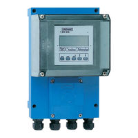
KROHNE IFC 010 F Installation And Operating Intructions (67 pages)
Signal converters intructions for electromagnetic flowmeters
Brand:
KROHNE
| Category:
Media Converter
| Size: 0 MB
Table of Contents
Table of Contents
2
Versions IFC 010 Signal Converter
4
Items Included with Supply
4
Software History
4
System Description
5
Product Liability and Warranty
5
CE / EMC / Standards / Approvals
5
Part a System Installation and Start-Up
6
Connection to Power
7
Electrical Connection of Separate Primary Head (F Version)
8
General Information on Signal Cable a and Field Current Cable C
8
Grounding of Primary Head
8
Cable Length (Max. Distance between Signal Converter and Primary Head)
10
Connection Diagrams I and II (Power Supply, Converter and Primary Head)
11
Current Output I
12
1 Electrical Connection: Power Supply
6
Cable Entries
6
Important Installation Notes PLEASE NOTE
6
Location
6
Only for Separate Systems/Signal Converters (F Versions)
6
2 Electrical Connection of Outputs
12
Pulse Output P and Status Output S
12
Power-On and Measurement
14
3 Start-Up
14
Factory Settings
15
Krohne Operator Control Concept
16
Part B IFC 010 / D Signal Converter
16
Operating and Check Elements
17
Function of Keys
18
Table of Settable Functions
20
Error Messages in Measuring Mode
24
Examples of Setting the Signal Converter
25
Reset Totalizer and Cancel Error Messages, RESET/QUIT Menu
25
4 Operation of the Signal Converter
16
5 Description of Functions
26
Full-Scale Range Q
26
Time Constant
26
Display
27
Low-Flow Cutoff
27
Internal Electronic Totalizer
28
Current Output I
29
Pulse Output P
30
Status Output S
32
Entry Code
33
Language
33
Primary Head
34
User-Defined Unit
35
Characteristic of Outputs
36
F/R Mode, Forward/Reverse Flow Measurement
36
Applications
37
Setting Data
37
HHT 010 Hand Held Terminal and RS 232 Adapter Incl. CONFIG Software (Options)
38
Part C Special Applications, Functional Checks, Service, and Order Numbers
38
6 Special Applications
38
Stable Signal Outputs When Measuring Tube Empty
39
7 Functional Checks
40
Test of Measuring Range Q, Fct. 2.01
40
Hardware Information and Error Status, Fct. 2.02
41
Faults and Symptoms During Start-Up and Process Flow Measurement
42
With HHT
44
Test of Primary Head
46
Test of Signal Converter 7.6
47
Test of Signal Converter Using GS 8A Simulator (Option)
48
Cleaning the Signal Converter Housing 8.1
51
Replacement of Power Fuse(S) 8.2
51
8 Service
51
Changeover of Operating Voltage on AC Versions 1, 2 and 3 (Not DC Version)
52
Replacement of Electronic Unit of Signal Converter
52
Illustrations to Sect. 8.2 to 8.7
53
Retrofitting the Display Unit
54
Turning the Display PCB
54
Illustrations of the Pcbs
56
9 Order Numbers
57
Full-Scale Range Q
58
Part D Technical Data, Measuring Principle and Block Diagram
58
10 Technical Data
58
Error Limits at Reference Conditions
59
IFC 010 Signal Converter
60
IFC 010 F and ZD Dimensions and Weights
61
Instrument Nameplates
62
Measuring Principle and Function of the System
63
12 Block Diagram - Signal Converter
64
Index
65
Advertisement
Advertisement
Related Products
Krohne ifc 300
KROHNE IFC 090 K
KROHNE IFC 090 F
KROHNE IFC 010 K
KROHNE IFC 070
KROHNE IFC 050
KROHNE IFC 090
KROHNE IFC 090 i
KROHNE IFC 020 K
KROHNE IFC 020 F
KROHNE Categories
Measuring Instruments
Transmitter
Switch
Accessories
Media Converter
More KROHNE Manuals
Login
Sign In
OR
Sign in with Facebook
Sign in with Google
Upload manual
Upload from disk
Upload from URL