Table of Contents
Advertisement
Advertisement
Table of Contents

Related Manuals for COBHAM SAILOR 4300


Summary of Contents for COBHAM SAILOR 4300
- Page 1 SAILOR 4300 L-Band System User manual...
- Page 3 SAILOR 4300 L-Band System User manual Document number: 98-159912-C Release date: 4 October 2018...
- Page 4 In the event of any discrepancies, the English version shall be the governing text. Thrane & Thrane A/S is trading as Cobham SATCOM. Manufacturer address Thrane & Thrane A/S, Industrivej 30, DK-9490, Pandrup, Denmark Copyright ©...
- Page 5 Write "source for product SAILOR 4300 L-Band System" in the memo line of your payment. This offer is valid to anyone in receipt of this information. http://www.cobham.com/communications-and-connectivity/satcom/free-and-open- source-software-foss/ Warranties Any attempt to install or execute software not supplied by Cobham SATCOM on this device will result in the warranty being void.
- Page 6 Safety summary The following general safety precautions must be observed during all phases of operation, service and repair of this equipment. Failure to comply with these precautions or with specific warnings elsewhere in this manual violates safety standards of design, manufacture and intended use of the equipment.
- Page 7 Service User access to the interior of the terminal is not allowed. Only a technician authorized by Cobham SATCOM may perform service - failure to comply with this rule will void the warranty. Access to the interior of the antenna is not allowed. Replacement of certain modules and general service may only be performed by a technician authorized by Cobham SATCOM.
- Page 8 Contact your authorized dealer for more information. About the manual Intended readers This manual is a user manual for the SAILOR 4300 L-Band System. This manual is intended for anyone who is using or intends to use this system. No specific skills are required to operate the SAILOR 4300 L-Band System.
-
Page 9: Table Of Contents
Table of contents Chapter 1 Introduction General description ................1 Overview ....................... 1 SAILOR 4338A Below Deck Unit (BDU) ..........1 SAILOR 4352A Above Deck Unit (ADU) ..........1 Data sessions and voice calls ..............2 IMEI and IMSI number .................. 3 Part numbers ...................3 Chapter 2 Operation... - Page 10 Table of contents Service and repair ................25 Disposal .......................25 App. A Specifications SAILOR 4300 L-Band System ............27 Glossary ........................31 Index ........................33...
-
Page 11: Chapter 1 Introduction
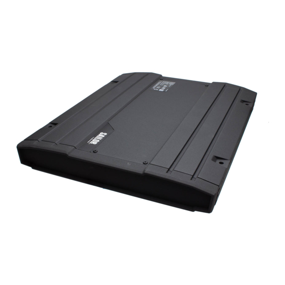
This chapter contains the following sections: • General description • Part numbers General description Overview The SAILOR 4300 L-Band System consists of an ADU (Above Deck Unit) and a BDU (Below Deck Unit). The two units are connected with a single coax cable with TNC connectors. -
Page 12: Data Sessions And Voice Calls
Chapter 1: Introduction Data sessions and voice calls The SAILOR 4300 L-Band System provides up to 3 IP voice calls and data sessions for multiple users simultaneous. The BDU has three user LAN ports for user data traffic, voice and data. The data session activation can be set to automatical or manual mode. -
Page 13: Imei And Imsi Number
ADU type label. The IMSI number is printed on the SIM card which you have received from your airtime provider. Part numbers This manual is for the SAILOR 4300 L-Band System and is applicable to the following part numbers: Part number... - Page 14 Chapter 1: Introduction Part numbers...
-
Page 15: Chapter 2 Operation
Chapter 2 Operation This chapter has the following sections: • Getting started • Connecting to the Internet • Making a voice call Getting started To insert the SIM card To be able to use the terminal you must have a valid SIM card. The SIM card is administrated by your airtime provider. -
Page 16: Power On
Chapter 2: Operation Power on Depending on which of the three possible power switch configurations is installed on the ship, the product is powered up as follows: • Using the on/off switch in the front panel of the SAILOR 4338A Below Deck Unit (bulk), see the following table. -
Page 17: To Connect A Pc And Sip Phone
LAN cable. SIP telephony service The SAILOR 4300 L-Band system has a built-in SIP server which provides up to three voice lines to users connected to the BDU. To use this service you need one or more VoIP-phone or soft-phone (mobile apps, PC software). - Page 18 Chapter 2: Operation subscribed mobile number to the SIP user name is fixed. For an example see the following table. Mapping from subscribed mobile numbers User name Mobile number Line type Voice quality line1 8816xxxxxxx1 PostPaid line2 8816xxxxxxx2 PostPaid line3 8816xxxxxxx3 PostPaid See your subscription information for the exact details on which mobile...
- Page 19 A VoIP-app on a mobile phone can only be used if the phone is connected to the device via a separate wireless router. Any modern SIP- telephone or software are suited for use with the SAILOR 4300 unit, though this cannot be guaranteed for a specific type of device or software.
-
Page 20: Connecting To The Internet
Chapter 2: Operation Connecting to the Internet Mobile web interface The purpose of the mobile web interface is to use the SAILOR 4300 L-Band System for starting Tap here and stopping data sessions and for menus view system events. To access available. -
Page 21: Start A Data Session
Chapter 2: Operation Menus in the mobile web interface The mobile web interface has the following top-level menus: • Status shows information such as system status, host name, position, statistics etc. • Data for start or stop of a data session (if Data Mode is set to Manual during installation). -
Page 22: Making A Voice Call
Chapter 2: Operation Making a voice call Call from the terminal To make a call from a phone connected to the SAILOR 4300 L-Band System: Example: To call Cobham SATCOM in Denmark: (+45 39558800): dial 00 <country code> <phone number> followed by press on call: 00 45 39558800 #. -
Page 23: Chapter 3 Service & Maintenance
• Service and repair Maintenance Maintenance of the SAILOR 4300 L-Band System can be reduced to a maintenance check at each visit of the service staff. Inspect the unit for mechanical damages, salt deposits, corrosion and any foreign material. Due to its robust construction and ruggedness the unit has a long lifetime. -
Page 24: Status Information In The Mobile Web Interface
Chapter 3: Service & maintenance Status information in the mobile web interface To display Status information in the mobile web interface, do as follows:. 1. Open the mobile web interface on your device. 2. The current status is displayed. In case a warning sign is displayed, you can tap on it to display the current system events. -
Page 25: Troubleshooting
Chapter 3: Service & maintenance • OVERHEATING. System is overheated. System is halted in 30 seconds • ERROR. A critical error is detected. See event list. The latest version of this manual is available in PDF format via the HELP menu. - Page 26 Chapter 3: Service & maintenance Power LED Indicator State Remedy pattern Power off Check if power is present. See section Power on on page 6. On (Green) Power on Normal operation. Terminal LED The terminal LED shows the status of the BDU, ADU and Iridium modem.
- Page 27 Chapter 3: Service & maintenance Indicator State Remedy pattern Green steady Terminal The terminal is operational and ready for ready use. Red steady Error (BDU, A fatal error is detected in the system. ADU or If possible, read out the event list. Iridium If a critical temperature is detected modem)
- Page 28 Chapter 3: Service & maintenance Indicator Meaning Remedy pattern Green steady Connected Normal system state, see Status information in the mobile web interface on page 14. Yellow steady Denied Service is denied on the Iridium network. Check SIM card status matches the requested service.
-
Page 29: Bite Events (Warning Sign)
Chapter 3: Service & maintenance BITE events (warning sign) BITE events are shown in the event list. The following table shows suggestions how to deal with the events. BITE ID System component Remedy (HEX) symptom 8301 ADU GPS module has Restart the terminal and see 8302 no connection... - Page 30 Chapter 3: Service & maintenance BITE ID System component Remedy (HEX) symptom 840B ADU PSU temperature The system will automatically 840C above warning level decrease the transmit ADU PSU temperature performance on temperature above critical level warnings. On detection of critical temperatures the system will protect itself by powering off the ADU.
- Page 31 Chapter 3: Service & maintenance BITE ID System component Remedy (HEX) symptom 8601 HPA Temperature The system will automatically 8602 above warning level decrease the transmit HPA Temperature performance on temperature above critical level warnings. On detection of critical temperatures the system will protect itself by powering off the ADU.
- Page 32 Chapter 3: Service & maintenance BITE ID System component Remedy (HEX) symptom 9002 BDU temperature above On temperature warnings try to 9003 warning level provide sufficient ventilation to BDU temperature above the terminal (opening lockers, critical level check fans, etc.). On detection of critical temperatures the system will halt completely after 30 seconds.
- Page 33 Chapter 3: Service & maintenance BITE ID System component Remedy (HEX) symptom 9601 Iridium modem reports Observe the number of this a reboot. event and report the event, if persistent, to your service partner. 9602 Iridium modem The system will automatically 9603 temperature above decrease the transmit...
-
Page 34: To Restart The Terminal
Chapter 3: Service & maintenance BITE ID System component Remedy (HEX) symptom 9902 Iridium modem self- Contact your service partner. check error 9903 Iridium modem reports Contact your service partner. wrong antenna type configuration 9A01 BDU boot-up problem. Restart the terminal (see below). System services may be not be available To restart the terminal... -
Page 35: Service And Repair
Service and repair Should your Cobham SATCOM product fail, please contact your dealer or installer, or the nearest Cobham SATCOM partner. You will find the partner details on www.cobham.com/satcom, Technical Service Partner List. You can also access the Partner Portal at www.cobham.com/satcom, Cobham SYNC Partner Portal, which may help you solve the problem. - Page 36 Chapter 3: Service & maintenance Service and repair...
-
Page 37: Sailor 4300 L-Band System
Appendix A Specifications SAILOR 4300 L-Band System Item Specification Weight, BDU 3.5 kg Weight, BDU, 19” 3.8 kg Weight, ADU 9.5 kg Dimensions, BDU 48 x 27 x 4 cm Dimensions, BDU, 19” 48 x 49 x 4 cm Dimensions, ADU ø=38 cm, H=37 cm... - Page 38 Automatic thermal surveillance shuts down system gradually in ease of own temperature BDU operating humidity 5% to 95% non-condensing at +40°C ADU enclosure IPX6 ADU operating humidity 5% to 95% Exposed according to EN 60945 BDU enclosure IP31 Icing (survival) Max 25 mm SAILOR 4300 L-Band System...
- Page 39 15 m/s (30 knots) Wind 200 km/hr (108 knots) MECHANICAL SHOCK Mechanical shock 20g/11 half-sine ANTENNA CONNECTOR TNC, female TNC, female OTHER SPECIFICATIONS Standard IP data rate, up/down 176/352 kbps Ethernet/LAN 4 ports I/O connector 1 connector SAILOR 4300 L-Band System...
- Page 40 Appendix A: Specifications Item Specification Status LED Full status LED panel SIM card slot 1 SIM card slot for Iridium SIM card SAILOR 4300 L-Band System...
-
Page 41: Glossary
Glossary Glossary Above Deck Unit Below Deck Unit General Public License General Public License, software license, which guarantees individuals, organizations and companies the freedom to use, study, share (copy), and modify the software. LGPL Lesser General Public License Power Supply Unit... - Page 42 Glossary...
-
Page 43: Index
Index Index approvals, vi warranty, 25 web interface connect, 10 configuration step-by-step, 10 connect web interface, 10 contact support, 13 IP address for web interface, 10, 11 maintenance, 13 part numbers, 25 Specifications, 27 standard compliance, vi static IP, 10 support contact info, 13... - Page 44 Index...
- Page 48 98-159912-C www.cobham.com/satcom...
Need help?
Do you have a question about the SAILOR 4300 and is the answer not in the manual?
Questions and answers