COBHAM SAILOR 100 GX Installation Manual
Satellite antenna
Hide thumbs
Also See for SAILOR 100 GX:
- Installation manual (215 pages) ,
- Technical manual (252 pages) ,
- Installation manual (6 pages)
Table of Contents
Advertisement
Quick Links
Advertisement
Table of Contents

Subscribe to Our Youtube Channel
Related Manuals for COBHAM SAILOR 100 GX


Summary of Contents for COBHAM SAILOR 100 GX
- Page 1 SAILOR 100 GX Installation manual...
- Page 2 Quick guide Configuration tasks (minimum) This quick guide aims at experienced service personnel who have installed the SAILOR 100 GX system and connected power. It lists the minimum configuration tasks you have to make before the system can be used on-air on a satellite.
- Page 3 SAILOR 100 GX Installation manual Document number: 98-141779-C Release date: 22 February 2017...
- Page 4 SW Technology/GPL Compliance, Cobham SATCOM (Thrane & Thrane A/S), Lundtoftegaardsvej 93D 2800 Lyngby DENMARK Write "source for product SAILOR 100 GX" in the memo line of your payment. This offer is valid to anyone in receipt of this information. http://www.cobham.com/about-cobham/communications-and-connectivity/about-us/satcom/free-and- open-source-software-(foss).aspx 98-141779-C...
- Page 5 Safety summary The following general safety precautions must be observed during all phases of operation, service and repair of this equipment. Failure to comply with these precautions or with specific warnings elsewhere in this manual violates safety standards of design, manufacture and intended use of the equipment.
- Page 6 ACU and Above Deck Unit can be extended if it complies with the specified data concerning cable losses etc. Rx and Tx cables for the SAILOR 100 GX system are shielded and should not be affected by magnetic fields. However, try to avoid running cables parallel to high power and AC/RF wiring as this might cause malfunction of the equipment.
- Page 7 Record of Revisions Rev. Description Release Date Initials Original document 22 September 2014 The following sections have been edited: Quick guide, 3.3.4, 5.3.2, 6.1.2, 6.2.1, 6.2.3, 6.2.5, App. D The following figures have been edited: 6-3, 6-5, 6-14, 15 December 2014 6-18 The following tables have been edited: 6-1, 6-8, 6-14, 6-19, 7-3...
- Page 8 98-141779-C...
-
Page 9: Table Of Contents
Satellite type approvals ....................2-8 2.1.6 Service activation ........................2-8 Part numbers and options ..................2-9 2.2.1 Applicable model and part numbers ................2-9 2.2.2 Options for SAILOR 100 GX ...................2-9 Chapter 3 Installation What’s in the box ......................3-1 3.1.1 To unpack ..........................3-1 3.1.2 Initial inspection ........................3-2... - Page 10 Table of contents Installation of the ADU .................... 3-18 3.3.1 Overview ..........................3-18 3.3.2 To install the ADU ......................3-18 3.3.3 To open and remove the service hatch ..............3-22 3.3.4 To ground the ADU ......................3-23 3.3.5 Alternative ADU cable ....................3-24 Installation of the ACU ....................
- Page 11 To connect the power cable to the ACU and GMU ...........5-3 Power-up procedure .......................5-3 5.4.1 Initialisation steps in daily use ..................5-4 5.4.2 SAILOR 100 GX operational ...................5-4 Chapter 6 Configuration Introduction to the built-in web interface ..........6-1 6.1.1 Overview ..........................6-1 6.1.2...
- Page 12 Frequently asked questions .................. 8-23 8.8.1 Overview ..........................8-23 8.8.2 The questions ........................8-24 To return units for repair ..................8-35 Appendix A Technical specifications SAILOR 100 GX system components ..............A-1 A.1.1 General specifications .......................A-1 A.1.2 ADU ............................A-2 A.1.3 ACU ............................A-4 A.1.4 GMU ............................A-5...
- Page 13 Table of contents Outline drawings .......................A-6 A.2.1 ADU ............................A-6 A.2.2 ACU ............................A-7 A.2.3 Modem .............................A-8 A.2.4 N-connector interface on the ADU .................A-10 Appendix B Ground and RF protection Why is a ground connection required? ............B-1 B.1.1 Safety ............................B-1 B.1.2 ESD Protection ........................B-1 Recommendations ......................B-2 B.2.1 To ground the ACU ......................B-2...
- Page 14 Table of contents Appendix D Command line interface Introduction ........................D-1 D.1.1 Telnet connection ......................D-1 D.1.2 Help ............................D-2 D.1.3 Conventions ......................... D-2 Supported commands ....................D-2 D.2.1 config ............................D-3 D.2.2 demo ............................D-3 D.2.3 dual_antenna ........................D-3 D.2.4 exit ............................
-
Page 15: About This Manual
About this manual Intended readers This is an installation and service manual for the SAILOR 100 GX system, intended for installers of the system and service personnel. Personnel installing or servicing the system must be properly trained and authorized by Cobham SATCOM. It is important that you observe all safety requirements listed in the beginning of this manual, and install the system according to the guidelines in this manual. -
Page 16: Typography
Typography Typography In this manual, typography is used as indicated below: Bold is used for the following purposes: • To emphasize words. Example: “Do not touch the antenna”. • To indicate what the user should select in the user interface. Example: “Select SETTINGS >... -
Page 17: Chapter 2 Introduction
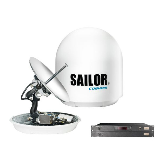
2.1.1 Overview The SAILOR 100 GX is a unique stabilized maritime GX antenna system operating in the Ka- band (19.2 to 30 GHz). It is used with the Global Xpress service from Inmarsat, delivering consistent high-performance download speeds of up to 50 Mbps and 5 Mbps over the uplink. - Page 18 SAILOR 100 GX system The following figure shows the SAILOR 100 GX system. Above Deck Unit (ADU) Antenna Control Unit (ACU) GX Modem Unit (GMU) Figure 2-2: ADU, ACU and GMU SAILOR 100 GX features Single 50 Ohm coax cable for the ADU.
-
Page 19: Above Deck Unit (Adu)
2.1.2 Above Deck Unit (ADU) The SAILOR 100 GX ADU is a 103 cm stabilized tracking antenna, consisting of a suspended antenna with a standard global RF configuration. It is stabilized by heavy duty vibration dampers in 3-axis (plus skew) and can be used in environments with elevations of -25° to + 125°. - Page 20 SAILOR 100 GX system Modules in the SAILOR 100 GX ADU Figure 2-4: Above Deck Unit modules 1/2 1. GNSS module. 2. VSAT Interface Module (VIM). 3. Pedestal Control Module (PCM). 4. Service switch. In switch-off position the Motor Driver modules and the BUC are turned off for safe conditions during service and repair.
- Page 21 SAILOR 100 GX system 8. Motor Driver Module for elevation (on the bottom) (DDM/SMD). 9. Elevation motor and encoder (not visible). 10. BUC Control Module (BCM). 11. Block Up Converter (BUC). 12. Low Noise Block downconverter (LNB). 13. Polariser. 14. Inertial Sensor Module (ISM).
-
Page 22: Antenna Control Unit (Acu)
SAILOR 100 GX system Four lifting brackets (included in the delivery) and reuse of packing material help getting the ADU safely into place. Satellite profile parameters are entered in the built-in web server of the ACU, using a PC. The system configuration is saved in two modules, there is no loss of data at repair. - Page 23 SAILOR 100 GX system ACU interfaces (AC powered) The ACU (SAILOR 7016C) has the following interfaces: Figure 2-7: ACU (connector panel) • N-connector for ADU cable (50 Ohm). • 2 x F connectors for Rx and Tx cables (75 Ohm) to modem.
-
Page 24: Gx Modem Unit (Modem)
For a list of satellite type approvals see Appendix E, Approvals. 2.1.6 Service activation Before you can start using the SAILOR 100 GX, you need to activate the system for the GX service. Contact your service provider for activation. Chapter 2: Introduction... -
Page 25: Part Numbers And Options
Part numbers and options Part numbers and options 2.2.1 Applicable model and part numbers The following model and part numbers are available for the SAILOR 100 GX system: Part number Description 407009C-00500 Above Deck Unit (ADU) for DC power 407009C-00501... - Page 26 Part numbers and options 2-10 Chapter 2: Introduction 98-141779-C...
-
Page 27: Installation
Chapter 3 Installation This chapter has the following sections: • What’s in the box • Site preparation • Installation of the ADU • Installation of the ACU • Installation of the modem • To connect the ADU, ACU and modem What’s in the box 3.1.1 To unpack... -
Page 28: Initial Inspection
What’s in the box 3.1.2 Initial inspection Inspect the shipping cartons and wooden box immediately upon receipt for evidence of damage during transport. If the shipping material is severely damaged or water stained, request that the carrier's agent be present when opening the cartons and wooden box. Save all box packing material for future use. -
Page 29: Site Preparation
1. Mount the ADU on stiffened structures with a minimum of exposure to vibrations. You do not have to align the ADU with the bow-to-stern line of the ship. When configuring the SAILOR 100 GX system, the azimuth calibration provides the correct azimuth of the ADU. -
Page 30: Obstructions (Adu Shadowing)
Site preparation 3.2.2 Obstructions (ADU shadowing) The ADU is stabilized in 3-axis (plus skew) and can be used in environments with elevations of -25° to + 125° to allow for continuous pointing even in heavy sea conditions. The ADU beam is approximately 1 m in diameter for the first 30 m from the ADU. Beyond 30 m the beam gradually widens so that it is approximately 5 m in diameter at 100 m distance. -
Page 31: Blocking Zones With Azimuth And Elevation
Site preparation 3.2.3 Blocking zones with azimuth and elevation Your installation may require that you set up blocking zones for the ADU, i.e. areas where the ADU will not transmit and areas where transmit power is potentially dangerous for persons frequently being in these zones. You can set up 8 blocking zones. Each blocking zone is set up with azimuth start and stop, and elevation angle. -
Page 32: Safe Access To The Adu (Radiation Hazard)
Site preparation 3.2.4 Safe access to the ADU (radiation hazard) The ADU radiates up to 54.5 dBW EIRP. This translates to a minimum safety distance of 30 m from the ADU while it is transmitting, based on a radiation level of 10 W/m MICROWAVE RADIATION NO PERSONNEL within safety distance of 30 m, based on 10 W/m... -
Page 33: Ship Motion And Offset From The Ship's Motion Centre
Site preparation 3.2.5 Ship motion and offset from the ship’s motion centre When installing the ADU you must consider the mounting height carefully. The higher up the ADU is mounted, the higher is the linear g force applied to the ADU. The g force also depends on the roll period of the ship, see Table 3-1. -
Page 34: Mast Foundation And Height
Site preparation 3.2.6 Mast foundation and height The ADU mast must be designed to carry the weight of the ADU (126 kg), plus the weight of the mast flange. The mast must also be able to withstand on-board vibrations and wind speeds up to 110 knots on the radome, even in icing conditions. - Page 35 Site preparation CAUTION! Avoid sharp edges where the flange is in direct contact with the radome. Round all edges as much as possible to avoid damaging the surface of the radome. 3. Allow sufficient space so the nut is free of the welded seam and there is room for tools (min.
- Page 36 Site preparation Mast length and diameter The placement of the ADU must ensure a rigid structural connection to the hull or structure of the ship. Parts of the ship with heavy resonant vibrations are not suitable places for the ADU. A small platform or short mast shall provide rigid support for the ADU fastening bolts and a rigid interface to the ship.
- Page 37 Site preparation Bracing and rigid masts can still not prevent vertical vibration if the mast is Note attached to a deck plate that is not rigid. Make every effort to mount the mast on a surface that is well supported by ribs. If this is not possible, provide extra deck plate propping.
- Page 38 Site preparation Outer Max. free Outer Wall Thickness Diameter Mast with 3 braces mast length Diameter Thickness for brace for brace (steel), (m) (mm) (mm) (mm) (mm) 30-40° Table 3-3: Mast dimensions with 3 braces Max. free Outer Thickness Outer Wall mast Diameter...
-
Page 39: Interference From Radar, Gps, L-Band And Other Transmitters
(below approximately 10 m) between radar antenna and the SAILOR 100 GX ADU. Therefore it is recommended to ensure as much vertical separation as possible when the SAILOR 100 GX ADU has to be placed close to a radar antenna. - Page 40 S band. If the d min. separation listed below is applied, antenna damage is normally avoided. “d min.” is defined as the shortest distance between the radar antenna (in any position) and the surface of the SAILOR 100 GX ADU. X-band (~ 3 cm / 10 GHz) damage distance SAILOR 100 GX ADU...
- Page 41 Even at distances greater than “d min.” in the previous section the radar might still be able to degrade the performance of the SAILOR 100 GX system. The presence of one or more S or X-band radars within a radius up to 100 m may cause a minor degradation of the Ka- band connection.
- Page 42 Site preparation Other transmitters See the following figure for minimum recommended distance to transmitters in the frequency range below 1000 MHz. Figure 3-13: Recommended distance to transmitters (m) for frequencies below 1000 MHz 3-16 Chapter 3: Installation 98-141779-C...
-
Page 43: Condensation, Water Intrusion And Deposits
Site preparation 3.2.8 Condensation, water intrusion and deposits In some weather conditions there may occur condensation inside the radome. The drain tube is designed to lead any water away from inside the radome. Observe the following guidelines for condensation and water intrusion: 1. -
Page 44: Installation Of The Adu
Installation of the ADU Installation of the ADU 3.3.1 Overview The following sections describe the installation and grounding of the antenna. The ADU is shipped fully assembled. You have to install it on the mast and attach the ADU cable. WARNING! Use a strong webbed sling with a belt to lift the ADU without damaging the radome. -
Page 45: Installation Procedure
Installation of the ADU • Maximum allowed cable loss 20 dB at 1950 MHz. This is to ensure optimum performance of the system. Installation procedure To install the ADU, do as follows: 1. Install the mast with the mast flange and have the 4 M12 bolts ready. 2. - Page 46 Installation of the ADU Figure 3-17: Mounting the ADU on the mast flange 10. Put the coaxial ADU cable through the protection plate as shown in the following figure and connect the N connector of the ADU cable to the ADU. 3-20 Chapter 3: Installation 98-141779-C...
- Page 47 Installation of the ADU 11. Select a suitable size for the cable gland: 16–20 mm diameter or 19–23 mm diameter. See also N-connector interface on the ADU on page A-10 for a more detailed drawing how to connect the N-connector on the ADU. Protection plate N connector Figure 3-18: Connecting the ADU cable...
-
Page 48: To Open And Remove The Service Hatch
Installation of the ADU 3.3.3 To open and remove the service hatch Through the service hatch you can access the antenna modules. You can remove the hatch for better mobility when servicing the antenna. Do as follows to open and remove the service hatch: 1. -
Page 49: To Ground The Adu
Installation of the ADU 3.3.4 To ground the ADU The ADU must be grounded using one of the mounting bolts. To ground the ADU do as follows: 1. Clean the metal underneath the head of at least one bolt of insulating protective coating and use a serrated washer to obtain a good ground connection 2. -
Page 50: Alternative Adu Cable
Installation of the ADU 3.3.5 Alternative ADU cable The maximum allowed RF loss in the antenna cable is 20 dB RF loss @ 1950 MHz and maximum 35 dB RF loss @ 4450 MHz. You can verify the cable attenuation margin with the cable calibration, see Cable calibration on page 6-11 for more details. -
Page 51: Installation Of The Acu
Installation of the ACU Installation of the ACU The following sections describe the installation and grounding of the ACU. 3.4.1 To install the ACU To install the ACU, do as follows: 1. Slide the ACU into a 1U space in a 19” rack. 2. -
Page 52: Installation Of The Modem
Installation of the modem Installation of the modem The following sections describe the installation and how to ground the modem. 3.5.1 To install the modem To install the modem, do as follows: 1. Slide the modem into a 1U space in a 19” rack, preferably directly below or above the ACU. -
Page 53: To Connect The Adu, Acu And Modem
To connect the ADU, ACU and modem To connect the ADU, ACU and modem The following sections show how to connect the ADU, ACU and the modem. 3.6.1 ACU with AC power (SAILOR 7016C) 1. Connect the antenna cable to Antenna at the ACU and the antenna. Service port for control PC Figure 3-25: Connection between ADU, ACU and modem (AC powered) -
Page 54: Acu With Dc Power (Sailor 7016B)
To connect the ADU, ACU and modem 3.6.2 ACU with DC power (SAILOR 7016B) 1. Connect the antenna cable to Antenna at the ACU and the antenna. Service port for control PC Figure 3-26: Connection between ADU, ACU and modem (DC powered) 2. -
Page 55: Interfaces Of The Acu
Chapter 4 Interfaces This chapter has in the following sections: • Interfaces of the ACU • Interfaces of the modem Interfaces of the ACU 4.1.1 LEDs, display, keypad and connectors The following figure shows the LEDs, display and the keypad of the ACU. For an explanation of the texts in the display see ACU display and keypad on page 6-33. -
Page 56: Ac Input Connector
Interfaces of the ACU Figure 4-3: ACU (connector panel) with DC power The connector LAN on the front panel is typically connected to the service port at LAN3 with a straight Ethernet cable. Then you can access the service port from the front of the ACU. -
Page 57: Adu Connector
Interfaces of the ACU DC input: Female plug (Weidmuller, Part number 1930050000) for wires up to AWG10/6 mm (included in the delivery). Outline (on the ACU) Pin function Wire color Left Vin+ Right Vin- Black Table 4-2: DC Input plug, outline and pin assignment 1. -
Page 58: Rx In And Tx Out Connectors
Interfaces of the ACU 4.1.5 Rx In and Tx Out connectors The ACU has an Rx Out and a Tx In connector. Use these connectors to connect the ACU to the modem. Outline (on the ACU) Pin number Pin function Inner conductor: reference clock, Rx/Tx Outer conductor: GND (Shield) -
Page 59: And Rs-422 Connectors
Interfaces of the ACU NMEA 0183 The NMEA 0183 connection supports EN 61162-1 (baud rate 4800, format 8N1) and EN 61162-2 (baud rate 38400, format 8N1). The ACU detects the baud rate automatically, you cannot configure this interface. Supported NMEA sentences: •... -
Page 60: Lan1 - 4 Connectors
LAN connector of the ACU for system control. 4. Use Port 4 (network 3) to connect the SAILOR 100 GX to the vessel’s LAN For more details about the LAN networks see To configure the LAN network on page 6-20. -
Page 61: Interfaces Of The Modem
Interfaces of the modem Interfaces of the modem The following sections describe the connectors of the modem and how to connect to the ACU, power and other equipment. 4.2.1 Connector panel The following figure shows the connector panel of the modem. Figure 4-5: Connector panel of the modem 4.2.2 Rx In and Tx Out connectors... -
Page 62: And Rs-422 Connectors
Interfaces of the modem 4.2.3 RS-232 and RS-422 connectors The modem has two RS-232 and one RS-422 connector for control information to and from the ACU. See section To connect the ADU, ACU and modem on page 3-27 for details how to connect the ACU to the modem. -
Page 63: Lan Connectors (8 + 2)
Interfaces of the modem 4.2.4 LAN connectors (8 + 2) The modem has 8 Ethernet connectors (type RJ45). Port 1 connects to the ACU and is used for modem control. The other ports are not used. The maximum cable length per connection is 100 m. - Page 64 Interfaces of the modem 4-10 Chapter 4: Interfaces 98-141779-C...
-
Page 65: Power And Startup
Chapter 5 Power and startup This chapter has the following sections: • Only DC powered ACU: Power source • Only DC powered ACU: Power cables • Only DC powered ACU: Power up Only DC powered ACU: Power source The ACU is powered with DC power. There are different options for the power supply: •... - Page 66 Only DC powered ACU: Power cables Example: 1 A and 50 mV. Source impedance: 50 mV/1 Amp = 50 mOhm. Figure 5-1: Measuring the ship source impedance If the total impedance is higher than the maximum stated further below in this Note section, the terminal may become unstable and start to on/off oscillate.
-
Page 67: Power Cable Of The Modem
• ADU POST • READY This may take some time (up to a couple of minutes). 3. The SAILOR 100 GX is ready to be calibrated (for first time power up) or receive data from the modem (when in normal operation). 98-141779-C... -
Page 68: Initialisation Steps In Daily Use
• POINTING ANTENNA • ACQUIRING SIGNAL • TRACKING 5.4.2 SAILOR 100 GX operational When the display shows TRACKING. MDM: NETOK and the LED Logon is steady green the system is operational. Figure 5-4: ACU display, system operational Chapter 5: Power and startup... -
Page 69: Configuration
Introduction to the built-in web interface 6.1.1 Overview With the built-in web interface of the SAILOR 100 GX ACU you make a full configuration of the SAILOR 100 GX. You can use a standard Internet browser. Installation of software is not necessary. - Page 70 3. Connect a PC to LAN port 3: Service (standard Ethernet) of the ACU or to the front LAN connector of the ACU. Figure 6-1: LAN 3 connector used for configuration of the SAILOR 100 GX If you want to use another LAN port to access the web interface you must configure it as described in To configure the LAN network on page 6-20.
- Page 71 Introduction to the built-in web interface Figure 6-3: Dashboard (example) For a detailed introduction to the web interface see Overview and dashboard on page 6- 98-141779-C Chapter 6: Configuration...
-
Page 72: Heading Input And Position System
Make sure that the modem is switched off at this point. Switch on the Important modem after the cable calibration. Before the SAILOR 100 GX can be used you must select the heading input and the positioning system. You must be logged on as an administrator. See Administration on page 6-29. - Page 73 (fixed heading). 5. For GNSS System, select from GPS, Beidou, GPS and Beidou, GPS and GLONASS. The SAILOR 100 GX uses GPS by default 6. For Manual enter the latitude, longitude and altitude. 7. Click Apply.
- Page 74 Heading input and position system Background information on the acquisition process and search pattern With heading input or fixed heading 1. The antenna starts the acquisition and searches for 10 seconds at the expected position. If RX lock is detected the antenna goes to Tracking. 2.
-
Page 75: Calibration
Service profile to be used for the azimuth calibration. A cable calibration is required in order to record the cable characteristics of the antenna cable which is used in the SAILOR 100 GX fixed gain feature. See Fixed TX IF principle on page 6-13 for more information. After the calibration you can set up blocking zones for the specific installation. - Page 76 Calibration Satellite Position Frequency Satellite identifier 62.6 E 19.707 GHz GSC 180 W 19.707 GHz GSC 55 W 19.707 GHz GSC Table 6-3: Inmarsat GSC satellite information The calibration function is not able to verify the correctness or precision of Important the supplied longitude.
- Page 77 Calibration this feature you must have made a valid satellite profile and activate it. When the vessel leaves the harbour and gets line of sight to the GX satellite, the system automatically finds and tracks the satellite and makes the azimuth calibration. After a successful azimuth calibration the ACU will automatically disable the Azimuth calibration (active satellite profile) on the page SERVICE >...
-
Page 78: Service Profile For Calibration
Calibration 2. Select the service profile in the drop down list Satellite. All profiles with the modem Service modem are displayed in the list. If there is no profile in the list, you must set up one, see Service profile for calibration on page 6-10. 3. -
Page 79: Cable Calibration
Calibration 7. Click Apply to save the settings for this satellite profile for calibration. The system is ready for the azimuth calibration. 8. Click Start to start the azimuth calibration. 6.3.3 Cable calibration Make sure that the modem is not switched on at this point. The modem can Important be switched on after the cable calibration. -
Page 80: Manual One Touch Commissioning (Buc Calibration)
Calibration 6.3.4 Manual One Touch Commissioning (BUC calibration) When the modem starts up for the first time it will automatically register with the BUC and perform P1dB compression on multiple frequencies and thereafter register with the Inmarsat network. During the P1dB compression the antenna will point away from the satellite and transmit on 950 MHz to 1950 MHz in 50 MHz steps. -
Page 81: Operation In Gyro-Free Mode
(software upgrades, if available). 8. The web interface of the iDirect core module will indicate the modem in the network as well as the modem status in the display in the menu MODEM of the SAILOR 100 GX web interface. -
Page 82: Configuration With The Web Interface
Configuration with the web interface Configuration with the web interface 6.4.1 Overview and dashboard Topics in the web interface The site map gives an overview over the existing menus, submenus and topics. You can click on each menu in the site map to go directly to the page or display the respective submenu. - Page 83 Configuration with the web interface The web interface has the following sections: Figure 6-13: Web interface: DASHBOARD of SAILOR 100 GX (example) 1. The navigation pane holds the main menu. Clicking an item in the menu opens a submenu in the navigation pane or a new page in the contents section.
- Page 84 Configuration with the web interface To navigate the web interface • To expand a menu, click the menu in the navigation pane. • To access status and settings, click the relevant subject in the navigation pane or click the relevant icon in the icon bar. The status or settings are displayed in the contents section.
- Page 85 28.05 GHz (system hardware) ACU part name, Part names, serial numbers for ACU and ADU, software version of Antenna part name, the SAILOR 100 GX. ACU serial number, Antenna serial number, Software version Table 6-6: Web interface, DASHBOARD, first section a.
-
Page 86: To Set Up Blocking Zones (Rx And Tx)
Description BUC TX On or Off. Shows if the SAILOR 100 GX has enabled the BUC or not. It is the same TX ON/TX OFF as shown in the display of the ACU, see ACU display and keypad on page 6-33. - Page 87 Configuration with the web interface To define and set a blocking zone, do as follows: 1. Select SETTINGS > Blocking zones. 2. Select Active to enable the blocking zone. 3. Enter start and stop azimuth value in degrees for the blocking zone. Values allowed: 0 to 360 degrees.
-
Page 88: To Configure The Lan Network
Internet. It must be located behind a dedicated network security device such as a fire wall. If any ports of the SAILOR 100 GX are exposed to the Internet you must change the default passwords as anyone with access and malicious intent can render the SAILOR 100 GX inoperable. - Page 89 Configuration with the web interface Figure 6-17: Web interface: SETTINGS, Network (default settings) Make sure that the networks do not use IP address ranges that overlap. Important Make the necessary changes on this page and click Apply. Sections Preferred use NETWORK Host The host name is used for identifying the ACU in local networks and in name...
- Page 90 Configuration with the web interface Sections Preferred use LAN Port 2 LAN port 2 is used for Internet access or Inmarsat Network Service Device (NSD). LAN Port 3 LAN port 3 is the service port. The default IP address is http://192.168.0.1;...
-
Page 91: E-Mail Setup
Configuration with the web interface Zeroconf Settings On LAN ports 1,3 and 4 you can choose to add a zeroconf address in the network (169.254.0.0).This zeroconf address will be in addition to the existing static or DHCP IP address. One port at a time can be enabled. Zeroconf allows devices to connect to a network automatically. -
Page 92: Setup Of Reports, Syslog And Snmp Traps
Configuration with the web interface 6.4.5 Setup of reports, syslog and SNMP traps The antenna can send the following reports and messages: • Diagnostics report • Statistics report • Remote syslog • SNMP traps Figure 6-19: Web interface: SETTINGS, Reporting Diagnostics report The antenna can send automatically generated diagnostic reports at fixed intervals. - Page 93 8-3. Statistics report SAILOR 100 GX can send a statistics report at fixed intervals through an external Internet connection. This report contains historical information from the SAILOR 100 GX up to 1 month. It contains statistics data for the selected intervals. The report is sent as a zipped attachment to an e-mail address.
- Page 94 Configuration with the web interface Parameter recorded Description UTC. (s) UTC in seconds and date format for the data set. UTC (YYYY-MM-DD hh:mm) RSSI.Av Received signal strength (average, maximum and RSSI.Max minimum value) for the sampling interval. RSSI.Min POS.Lat (degree) Latitude value of position.
- Page 95 Configuration with the web interface 360° 000° 315° 45° 270° 90° Antenna 225° 135° 180° Covered area: If range > 0: Go from Min to Max counterclockwise If range < 0: Go from Min to Max clockwise Figure 6-20: Statistics — how to read data for a range To import the statistics report into spreadsheet applications, e.g.
- Page 96 Configuration with the web interface Figure 6-21: Statistics report (example, MS Excel 2007) Remote syslog You can set up the antenna to send each syslog message to a syslog server to advise the system administrator of the current status of the antenna. To set up sending syslog messages to a syslog server, do as follows: 1.
-
Page 97: Administration
Configuration with the web interface 3. Enter the IP address of the SNMP trap receiver/manager to which the SNMP traps will be sent. 4. Enter the Community name. This is the name of the SNMP trap receiver/manager. This is needed for authentication of the SNMP trap request. 5. - Page 98 Configuration with the web interface To change the password and log off ADMINISTRATION and User login you can change the password for the On the page currently logged in user (admin or guest) or you can log off. Figure 6-23: Web interface: ADMINISTRATION, change administrator logon and password To change the current password, do as follows 1.
- Page 99 Configuration with the web interface To set up user permissions for guest login You can manage user access to certain functions of the SAILOR 100 GX. You can allow or deny users that are not administrators (user name: guest, password: guest) to access certain functions and make these pages read-only.
- Page 100 To import and export a system configuration If you need to reuse a configuration in another SAILOR 100 GX system, you can save the current configuration to a configuration file. This file can then be loaded into another SAILOR 100 GX or be used as backup.
-
Page 101: Keypad And Menus Of The Acu
Signal strength Figure 6-27: Display and keypad of the ACU (example) 1. Current status of the SAILOR 100 GX: NOT READY (waiting for input from GNSS, e.g. GPS) ANTENNA INITIALIZING ANTENNA SW UPLOAD... - Page 102 Keypad and menus of the ACU SAFE MODE (error, followed by an error description) SERVICE SWITCH (service switch in ADU activated) READY (waiting for data from the modem or no satellite profile selected) POINTING ANTENNA (locating the satellite) ACQUIRING SIGNAL (acquiring the satellite signal) TRACKING (tracks the current satellite) AZIMUTH CALIBRATION TX CABLE CALIBRATION...
-
Page 103: Navigating The Menus
Keypad and menus of the ACU 6.5.2 Navigating the menus Use the keypad to navigate the menus. • Press OK or to select a menu item. • Use the arrow keys to go through the menu items or enter a number, digit by digit. •... - Page 104 Top-level menu Description MAIN View with current status of the SAILOR 100 GX. Example when logged on to the satellite: This view is displayed after a time out of 10 minutes. Press any key (except left arrow) to enter the menu at MAIN.
- Page 105 Current IP address for LAN 1 MASK 1 Current netmask for LAN 1 PORT 3 IP (LAN 3) Current IP address of the SAILOR 100 GX web interface (default: http://192.168.0.1) MASK 3 (LAN 3) Current netmask of the SAILOR 100 GX web interface (default: 255.255.255.0)
-
Page 106: Brightness Of The Display
Keypad and menus of the ACU SATELLITE menu Description LNB LO HIGH Current LNB Local Oscillator frequency, high band (GHz), selected in the satellite profile LNB LO LOW Current LNB Local Oscillator frequency, low band (GHz), selected in the satellite profile Table 6-19: SATELLITE menu of the ACU (Continued) EVENT menu Description... -
Page 107: Snmp Support
SNMP is always enabled on all Ethernet interfaces. The SNMP community string is public. The SAILOR 100 GX offers via SNMP most of the data that are available from the DASHBOARD web pages. Detailed documentation about supported OIDs can be found in the SAILOR 100 GX MIB file. - Page 108 SNMP support 6-40 Chapter 6: Configuration 98-141779-C...
- Page 109 Chapter 7 Installation check Now that you have installed the system, you can test it to verify it is ready for customer delivery. Follow the check lists below to test the system for proper operation. • Installation check list: Antenna •...
-
Page 110: Installation Check List: Antenna
Installation check list: Antenna Installation check list: Antenna Step Task Further information Done Check that the antenna is free of obstructions. See Obstructions (ADU shadowing) on page 3-4. Make sure there is sufficient space for access See To install the ADU on page 3-18. through the service hatch. -
Page 111: Installation Check List: Acu And Modem, Connectors And Wiring
Installation check list: ACU and modem, connectors and wiring Installation check list: ACU and modem, connectors and wiring Step Task Verification and further information Done Check that the ACU is grounded correctly, See To ground the ACU on page 3-25 and using the mounting bolts and washers. -
Page 112: Installation Check List: Functional Test In Harbor
Installation check list: Functional test in harbor Installation check list: Functional test in harbor Step Task Further information Done Check that the antenna is The logon LED in the ACU display must be tracking the satellite steady green and the display must show: TRACKING. -
Page 113: Chapter 8 Service
Chapter 8 Service This chapter has the following sections: • To get support • Software update • Satellite profiles and modem profiles • Status signalling with LEDs and status messages • Removal and replacement of the ACU • Removal and replacement of ADU modules •... -
Page 114: To Get Support
3. To download the MIB file click the link. 4. Click the link Legal notices to see the licence text for the source code of the parts of the SAILOR 100 GX software that falls under free and open source software. Chapter 8: Service... - Page 115 To get support To download diagnostics and statistics reports You can download a diagnostic report. The diagnostics report contains information relevant for the service personnel during troubleshooting. It is also useful documentation of the current setup. It contains all parameters set during configuration. You can add diagnostic log information from the modem and the BUC.
- Page 116 Important perform the self test. Rebooting the ACU will terminate all existing connections. You can reset the SAILOR 100 GX modem to factory defaults. See Reset to factory default - GMU on page 8-7. Proxy server settings in your browser If you are connecting your computer using a LAN or WLAN interface, the Proxy server settings in your browser must be disabled before accessing the web interface.
- Page 117 To get support 2. Clear the box labelled Use a proxy server for your LAN. 3. Click OK. When the proxy server settings are disabled, close and restart your browser. You may need to change this setting back on return to your Internet connection. 98-141779-C Chapter 8: Service...
-
Page 118: Reset To Factory Default
To get support 8.1.2 Reset to factory default You can reset the SAILOR 100 GX ADU and ACU to factory default. Warning! Reset to factory default will delete all settings, including Important satellite and VSAT modem profiles, blocking zones, network setup, user permissions and ACU display brightness settings. -
Page 119: Reset To Factory Default - Gmu
The ship must not move during the line-up procedure. Note The SAILOR 100 GX has been tested at the factory and online on a live satellite link. You can also make a line up and adjust the azimuth and elevation manually. Do as follows: 1. - Page 120 To get support 4. Wait until the text next to Status shows: Ready for activation. Step 3 Step 4 Figure 8-4: Web interface: SERVICE, Line up: Ready for activation 5. Click the button Activate lineup and wait until the Status text shows Antenna ready.
-
Page 121: Software Update
This is shown in the ACU display as ADU SW UPLOAD. To make a software update, do as follows: 1. Power up the SAILOR 100 GX system, i.e. switch on the ACU. Wait until the ACU has finished initializing. 2. Connect a PC to LAN interface 3 (Service port, standard Ethernet) of the ACU or to the front LAN connector of the ACU. - Page 122 Software update 4. Type in the user name admin and the password 1234 to access the Dashboard. 5. The web interface shows the DASHBOARD page. 6. Click SERVICE in the navigation pane. The UPLOAD page is displayed. Figure 8-8: Software update with the web interface 7.
- Page 123 Software update Software recovery procedure (SAFE MODE) To recover from a failed software upload, turn off the ACU and turn it on again. Then repeat the upload procedure as described in Software update on page 8-9. If this does not help use the following recovery procedure: 1.
-
Page 124: Software Update (Modem)
Software update To verify the software update (ADU and ACU) The software version can be viewed in the DASHBOARD window of the web interface. After completing the software update procedure, the ACU will perform a POST (Power On Self Test). When the POST has finished, the green Pass/Fail LED on the front of the ACU must become steadily green. -
Page 125: Satellite Profiles And Modem Profiles
Satellite profiles and modem profiles Satellite profiles and modem profiles 8.3.1 Satellite profiles A satellite profile with the GX Modem is already set up at the factory. You may add a satellite profile with the generic modem for troubleshooting purposes. This is done on the page Satellite profiles. -
Page 126: Modem Profiles
Satellite profiles and modem profiles 2. Enter or edit the Satellite profile name. It is helpful to assign a name containing the location where Note the Satellite profile is to be used (e.g. Gulf of Mexico or North Sea) and possibly the provider. 3. - Page 127 Satellite profiles and modem profiles Figure 8-15: Web interface: SETTINGS, Modem profile – supported modems 2. Fill in a modem profile name of your own choice. 3. Select one of the supported modems from the drop down list. Generic modem: If you have a modem that is not included in the list, select the generic modem.
-
Page 128: Status Signalling With Leds And Status Messages
For details on error messages after a POST or a self test see Event list on page 8-4. Means of signalling The SAILOR 100 GX provides various methods for signalling the system status. LEDs on the front panel of the ACU are used to signal: •... -
Page 129: Leds In The Acu
Status signalling with LEDs and status messages 8.4.2 LEDs in the ACU The ACU has 3 LEDs: on the front panel: Power, Logon and Fail/Pass LED. Behaviour Description Power Steady green Power supply OK Steady red Power supply failure No power Logon Flashing Current status is displayed:... -
Page 130: Removal And Replacement Of The Acu
Removal and replacement of the ACU Removal and replacement of the ACU There are no parts in the ACU that you can remove or replace. Contact your Cobham SATCOM service partner for further repair or replacement. 8-18 Chapter 8: Service... -
Page 131: Removal And Replacement Of Adu Modules
Removal and replacement of ADU modules Removal and replacement of ADU modules All replacement of modules must be carried out by a Cobham SATCOM service partner. The figure below shows the modules and their position. Some modules are equipped with LEDs for status information and troubleshooting. - Page 132 Removal and replacement of ADU modules 4. Service switch. In switch-off position the Motor Driver modules (DDM/SMD), the BCM and the BUC are turned off for safe conditions during service and repair. The switch must be in on position for normal ADU operation. 5.
- Page 133 Removal and replacement of ADU modules Figure 8-18: Above Deck Unit modules 2/2 16. Motor Driver Module for Azimuth (DDM/SMD). As in item 3 above. 17. Azimuth motor. 18. Azimuth encoder. 19. Rotary joint. The cable signals for the ADU (DC power, internal modem communication, TX IF, RX and L-band TX) to and from the ACU have to be ported from the stationary platform to the azimuth rotating part of the ADU.
-
Page 134: Troubleshooting
8.7.1 Overview This section describes an initial check of the primary functions of the SAILOR 100 GX system, and provides some guidelines for troubleshooting. Generally, if a fault occurs without any obvious reason, it is always recommended to observe the LEDs and the ACU display showing the active events. -
Page 135: Frequently Asked Questions
Frequently asked questions Frequently asked questions 8.8.1 Overview The following sections are a collection of frequently asked questions with answers. • Q1: What is OTC and what happens? • Q2: The antenna points towards the wrong Inmarsat GX satellite, what do I do? •... -
Page 136: The Questions
Frequently asked questions 8.8.2 The questions Q1: What is OTC and what happens? OTC stands for One Touch Commission. OTC is similar to a P1dB compression test for VSAT but on multiple frequencies. The GMU will instruct the antenna to point away from the Clark belt (geostationary satellites), disable the Power Amplifier (PA) of the BUC and use a built-in Power Detector to measure the gain of the system from GMU tx-connector up to BUC PA. - Page 137 Frequently asked questions Q4: How do I start a manual OTC procedure? You start a manual OTC procedure from the web server of the GMU. The GMU (iDirect Core Module) does NOT support Internet Explorer, use Mozilla Firefox or Chrome! 1.
- Page 138 Frequently asked questions Q8: How do I log in to the GMU Linux shell? Make an SSH connection (Freeware: PuTTY.exe) to the ACU on IP port number 8022. Example: ssh 192.168.0.1:8022 User and Password: root / iDirect or root / iDirect123! Q9: ACU stays in BUC CALIBRATION state almost forever, what can I do? Make a new manual OTC and wait until the GMU reboots and sends a new pointing request to the ACU.
- Page 139 Frequently asked questions Go to ADMINISTRATION - TERMINAL to upload the new TERMINAL_OPT.json file. Figure 8-22: TERMINAL_OPT.json configuration file See also Q5: What is the login to the GMU webserver? on page 8-25. Q12: BUC calibration reports: "ERROR: Not Enough Modem Power During Ramping, BUC Not ready For OTC".
- Page 140 Frequently asked questions 2. Select the tab for the user VLAN number. It is most likely VLAN 1010 or VLAN 3901. Figure 8-24: IP address of PC 3. On the PC configure the GW, DNS and subnet mask to the IP address and Subnet Mask shown in the VLAN tab.
- Page 141 Frequently asked questions Q15: I do not have Internet access using the IP address for the UserNET VLAN. Why? 1. Go to the ACU web server SETTINGS - NETWORK. 2. Scroll down to the bottom to find the VLAN table which shows the network configuration done over the air by the Inmarsat system to the GMU.
- Page 142 Frequently asked questions 7. Use the command help to show all available GMU commands. Q17: The antenna is pointing in a wrong direction, what is wrong? You have probably not made an azimuth calibration yet, or maybe moved the antenna recently during a stationary test setup.
- Page 143 Frequently asked questions Q19: After successful azimuth calibration the antenna is still pointing in a wrong direction, what is wrong? You have made a successful azimuth calibration, but the antenna status stays in the status ACQUISITION. The reason for this may be that the antenna has found another GX satellite than the one you intended it to use for the azimuth calibration.
- Page 144 Frequently asked questions Azimuth calibration value Azimuth calibration Azimuth calibration Azimuth calibration must be in the range of value must be in the value must be in the value must be in the -10° to +10°. range of range of range of +170°...
- Page 145 Frequently asked questions 'Bad’ calibration Expected Azimuth Calibration value Between +170° and -170° Actual Azimuth calibration value -45.5° Position Copenhagen Satellite selected 62.6E Satellite found Table 8-5: Example of a bad calibration 0° -45.5° Service hatch -90° 90° Mast +-180° Figure 8-31: Example of a bad calibration How to correct the issue 1.
- Page 146 Frequently asked questions Q20: Why do I get the 08A02-0 ADM WARNING GX Core Module temperature? This warning is triggered by a temperature sensor in the GMU. The ambient temperature of the GMU is approaching the temperature limits of -25°C or +55°C. If the situation gets worse the GMU might automatically switch OFF in order to protect the electronics.
-
Page 147: To Return Units For Repair
To return units for repair To return units for repair Should your Cobham SATCOM product fail, please contact your dealer or installer, or the nearest Cobham SATCOM partner. You will find the partner details on www.cobham.com/satcom where you also find the Cobham SATCOM Self Service Center web-portal, which may help you solve the problem. - Page 148 To return units for repair 8-36 Chapter 8: Service 98-141779-C...
-
Page 149: Appendix A Technical Specifications
Appendix A Technical specifications This appendix has the following sections: • SAILOR 100 GX system components • Outline drawings SAILOR 100 GX system components A.1.1 General specifications Item Specification Frequency band Ka-Band (Inmarsat GX) 19.2 to 20.2 GHz 29.0 to 30.0 GHz Reflector size 103 cm (40.6 inch) -
Page 150: Adu
SAILOR 100 GX system components A.1.2 Item Specification antenna Antenna type, pedestal 3-axis (plus skew) stabilised tracking with integrated GNSS (GPS, GLONASS, Beidou) Antenna type, reflector system Reflector/sub-reflector, ring focus Transmit gain 47.5 dBi typ. @ 29.5 GHz (excluding radome) Receive gain 44.0 dBi typ. - Page 151 SAILOR 100 GX system components Item Specification Satellite acquisition Automatic Vibration, operational Sine: EN 60945 (8.7.2), DNV No.2.4 Class A, MIL-STD-167-1 (5.1.3.3.5) Random: Cobham Maritime Operational Vibration, survival Sine: EN 60945 (8.7.2) dwell, MIL-STD-167-1 (5.1.3.3.5) dwell. EN 60721-3-6 class 6M3 Shock MIL-STD-810F 516.5 (Proc.
-
Page 152: Acu
SAILOR 100 GX system components A.1.3 Item Specification Dimensions, rack mount 1 U, 19 inch H x W x D 4.4 x 48 x 33 cm (1.75 x 19 x 13 inch) Weight 4.5 kg (10 lbs) Connections ACU-GMU Mechanical and electrical connections pre-installed Ambient temperature Operational: -25°C to +55°C... -
Page 153: Gmu
SAILOR 100 GX system components A.1.4 Item Specification Dimensions, rack mount 1 U, 19 inch 4.4 x 48 x 33 cm (1.75 x 19 x 13 inch) H x W x D Weight 3.5 kg (7.7 lbs) Ambient temperature Operational: -25°C to +55°C Storage: -40°C to +85°C... -
Page 154: Outline Drawings
Outline drawings Outline drawings A.2.1 Figure A-1: Outline drawing: ADU Appendix A: Technical specifications 98-141779-C... -
Page 155: Acu
Outline drawings A.2.2 ACU with AC power (SAILOR 7016C) Figure A-2: Outline drawing: ACU, AC powered (SAILOR 7016C) 98-141779-C Appendix A: Technical specifications... -
Page 156: Modem
Outline drawings ACU with DC power (SAILOR 7016B) Figure A-3: Outline drawing: ACU, DC powered (SAILOR 7016B) A.2.3 Modem Appendix A: Technical specifications 98-141779-C... - Page 157 Outline drawings Figure A-4: OUtline drawing, GMU 98-141779-C Appendix A: Technical specifications...
-
Page 158: N-Connector Interface On The Adu
Outline drawings A.2.4 N-connector interface on the ADU Figure A-5: N-Connector interface on the ADU A-10 Appendix A: Technical specifications 98-141779-C... -
Page 159: Appendix B Ground And Rf Protection
• Jumper cable for grounding Why is a ground connection required? You must ground the SAILOR 100 GX system for at least two reasons: • Safety: Lightning protection of persons and equipment. • Protection: ESD (ElectroStatic Discharge) protection of equipment. -
Page 160: Recommendations
Recommendations Recommendations B.2.1 To ground the ACU To ground the ACU do as follows: 1. Ground the ACU to the ship/hull. For this purpose you may use a short ADU cable and a grounding kit. 2. Further, the ACU must be grounded at its grounding stud in order to ensure proper grounding if the short ADU cable is disconnected. -
Page 161: To Ground The Adu
Recommendations Per used jumper cable the maximum cable length of the cable to the antenna is reduced by: • Enviroflex 400: 1.25 m • SPUMA 400-FR: 6 m • SUCOFEED 1/2" FR: 10 m B.2.2 To ground the ADU To ground the ADU do as follows: 1. -
Page 162: Alternative Ground For Steel Hulls
Alternative ground for steel hulls Alternative ground for steel hulls The following guidelines assume a two-wire, isolated grounding arrangement; that is no part of the circuit, in particular the battery negative, is connected to any ground potential or equipment. B.3.1 To ground the ACU To ground the ACU do as follows: 1. - Page 163 Alternative ground for steel hulls The ADU must be electrically isolated at its mounting bolts Note by means of shoulder bushings and washers ensuring the isolated RF ground - see Isolation of the ADU from the mounting base on page B-9. Figure B-3: Grounding at a dedicated RF ground (alternative) 98-141779-C Appendix B: Ground and RF protection...
-
Page 164: Alternative Ground For Aluminum Hulls
Alternative ground for aluminum hulls Alternative ground for aluminum hulls The following guidelines assume a two-wire, isolated grounding arrangement; that is no part of the circuit, in particular the battery negative, is connected to any ground potential or equipment. B.4.1 To ground the ACU To ground the ACU do as follows: 1. -
Page 165: Alternative Ground For Fiber Glass Hulls
Alternative ground for fiber glass hulls Alternative ground for fiber glass hulls B.5.1 To ground the ACU To ground the ACU do as follows: 1. Preferably ground the ACU with the short ADU cable and a grounding kit (available from Thrane &... -
Page 166: Separate Ground Cable
Separate ground cable Separate ground cable B.6.1 To make a ground cable When dealing with electrical installations in a marine environment, all wiring must be done with double insulated, tinned strands, high quality and if exposed also UV resistant cables. This shall also apply to the separate ground cable mentioned in the previous paragraphs. -
Page 167: Isolation Of The Adu From The Mounting Base
Separate ground cable 4. If the ADU is to be isolated from the mounting base, use shoulder bushings and washer, see figure B-7, Isolation of the ADU from the mounting base on page B-9. 5. At the other end, connect the ground cable as described in To ground the ACU on page B-2. -
Page 168: Rf Interference
RF interference Interference induced from nearby high-power RF transmitters might cause system failures and in extreme cases permanent damage to the SAILOR 100 GX equipment. If there are problems with interference from HF transmitters, do as follows: 1. Mount ferrite clamps on the coax cable in order to provide suppression of induced RF. -
Page 169: Jumper Cable For Grounding
Jumper cable for grounding Jumper cable for grounding Figure B-9: Jumper cable for grounding (specifications) 98-141779-C Appendix B: Ground and RF protection B-11... - Page 170 Jumper cable for grounding B-12 Appendix B: Ground and RF protection 98-141779-C...
-
Page 171: Appendix C System Messages
• CM (Continuous Monitoring) – automatically performed while the system is in operation. When the SAILOR 100 GX detects an event that requires your action, it issues an event message and the red Fail/Pass LED in the LED panel of the ACU is lit. As long as an event is active, it is shown in the ACU display, the Control Panel and the web interface (in HELPDESK >... -
Page 172: List Of Adu Events
List of ADU events List of ADU events Error code Unit Severity Description Explanation (ID) 0A001-0 Antenna ERROR Production data Production data is invalid. 0A002-0 Antenna ERROR XIM internal Antenna configuration data stored in the PCM module is invalid. 0A003-0 Antenna ERROR XIM external Antenna configuration data stored in the VIM/TIM module is invalid. - Page 173 List of ADU events Error code Unit Severity Description Explanation (ID) 0A01E-0 Antenna ERROR Sensor sanity Too many invalid values measured by the ISM during initialisation. Check for vibrations or malfunctioning ISM. 0A021-0 Antenna ERROR Azi axis calibration Azimuth axis zero reference not found. Check belt and zero reference module.
- Page 174 List of ADU events Error code Unit Severity Description Explanation (ID) 0A039-0 Antenna WARNING GNSS device warning Local GNSS device warning. 0A03A-0 Antenna WARNING GNSS device error Local GNSS device error. 0A03B-0 Antenna ERROR Azi DDM shutdown The azimuth motor control has detected one of the following situations: Extreme temperature, voltage, current or velocity.
- Page 175 List of ADU events Error code Unit Severity Description Explanation (ID) 0A04F-0 Antenna WARNING Heading data Heading information is missing in the antenna. 0A050-0 Antenna ERROR Azi DDM Communication error between PCM and azimuth communication DDM. Check SUB-D connectors and cables. 0A051-0 Antenna ERROR Xel DDM Communication error between PCM and cross-...
- Page 176 List of ADU events Error code Unit Severity Description Explanation (ID) 0A059-0 Antenna WARNING Azi cal. limits Check limits of the calibration result for the azimuth axis are exceeded. Pointing performance may be degraded. Info: 0x00000040: End stop detected before expected limit 0x00000100: Zero width is low 0x00000200: Zero width is high...
- Page 177 List of ADU events Error code Unit Severity Description Explanation (ID) 0A066-0 Antenna ERROR OMT error Problem with OMT. Temperature out of range or OMT cable may be broken. 0A067-0 Antenna WARNING Automatic stow The antenna automatically stowed because it detected significant movement.
-
Page 178: List Of Acu Events
List of ACU events List of ACU events Error code ACU PCB Severity Description Explanation (ID) 08060-0 ADM WARNING Antenna modem ACU/Antenna communication error detected (framing and parity). If the situation is persistent, check if cable specifications comply (length and attenuation). - Page 179 List of ACU events Error code ACU PCB Severity Description Explanation (ID) 08078-0 ADM WARNING VMU TX frequency The satellite modem did not provide a Tx frequency, invalid or it is invalid. A default Tx frequency is assumed, but this may degrade Tx performance. To remove this warning re-configure the modem to provide the correct Tx frequency.
- Page 180 List of ACU events Error code ACU PCB Severity Description Explanation (ID) 08109-0 ADM ERROR Antenna XIM data There is a mismatch in the antenna configuration data. Either the PCM or the VIM in the antenna are malfunctioning or one of them has been replaced. In the latter case, select which is the original device in the web interface and restart the system.
- Page 181 List of ACU events Error code ACU PCB Severity Description Explanation (ID) 08A02-0 ADM WARNING GX Core Module The Core Module temperature is out of range. This temperature may affect performance, and the Core Module will be shut down if the situation gets worse. If the "GX core module heating"...
- Page 182 List of ACU events Error code ACU PCB Severity Description Explanation (ID) 0B060-0 PSM WARNING NMEA 0183 parse Parse errors detected on the NMEA 0183 interface. error Check NMEA 0183 cable, signal levels etc. 0B061-0 PSM WARNING Power supply ACU Power supply temperature is high. Improve temperature ventilation or move to a cooler area.
-
Page 183: Appendix D Command Line Interface
Appendix D Command line interface Introduction After you have done the initial configuration and connected the SAILOR VSAT system to your network, you can use Telnet to configure the SAILOR VSAT system. You can also set up VSAT modem parameters. Note that the following sections cover the command line interface for all SAILOR VSAT antennas. -
Page 184: Help
Supported commands D.1.2 Help If you enter help directly at the prompt UCLI:/$ all available commands are listed. Additionally any command will take help as first argument and display detailed information of the specific command. D.1.3 Conventions The command description below uses the following special typography: Convention Description Information that is displayed on the screen. -
Page 185: Config
Supported commands D.2.1 config Command Description Shows the sub commands available, including a short config description. config pending_list Shows the number of pending changes. config current_list Shows the values for the current satellite profile, antenna and some tracking information. Discards all pending changes. config discard Use this command to save and activate the pending config activate... -
Page 186: Help
Supported commands D.2.5 help Command Description Shows a list of commands available, including a short description. help help satellite Shows the sub commands and description for the command satellite. Shows the sub commands and a short description for the help modem command modem. -
Page 187: D.2.7 Satellite
Supported commands D.2.7 satellite Command Description Shows the name of the currently active satellite satellite name profile. Shows or sets the longitude position of the satellite, satellite lon in degrees. • 1.0W or 1.0E or -1.0 for west and 1.0 for east satellite lon 1W Shows or sets an additional skew offset of the satellite skew... - Page 188 Supported commands Command Description Shows or sets the Rx frequency and LNB Lo satellite rx_rf_freq frequency. • Ku band: satellite rx_rf_freq RF frequency: 10.7 – 12.75 GHz. 12.123456 9.75 LNB Lo frequency: 9.6 GHz – 11.3 GHz. The SAILOR VSAT system supports any LNB Lo. •...
-
Page 189: Status
Command Description Shows the sub commands available, including a short status description. Shows the current status of the SAILOR 100 GX. status system Shows the current values for all tracking parameters: status track_all • vessel heading • azimuth relative •... -
Page 190: System
Shows or sets the receiver bandwidth or mode, the way track mode the SAILOR 100 GX tracks the satellite: • narrow (recommended, uses the built-in 300 kHz track mode dvb filter of the SAILOR 100 GX) • rssi (uses the RSSI signal from the VSAT modem) •... -
Page 191: Zone
Supported commands Command Description Shows or sets the DVB NID to be verified by the built-in track dvb_nid DVB-S2 tracking receiver, when using tracking mode DVB. It configures the NID used to verify and track a track dvb_nid 0 transponder. •... - Page 192 Supported commands D-10 Appendix D: Command line interface 98-141779-C...
-
Page 193: Appendix E Approvals
This appendix lists the approvals for SAILOR 100 GX: • CE (R&TTE) CE (R&TTE) The SAILOR 100 GX is CE certified (R&TTE directive) as stated in the “Declaration of Conformity with R&TTE Directive”, enclosed in copy on the next page. 98-141779-C... - Page 194 CE (R&TTE) Appendix E: Approvals 98-141779-C...
- Page 195 CE (R&TTE) 98-141779-C Appendix E: Approvals...
- Page 196 CE (R&TTE) Appendix E: Approvals 98-141779-C...
-
Page 197: Glossary
Glossary Glossary ADU Bus Slave Antenna Control Unit ACU Digital Module. A main processor board in the ACU. Antenna Module Bus Block Up Converter - The BUC can be thought of the “transmitter”, and its actions are effectively the direct opposite to the LNB. The BUC consists of the Up Converter and HPA. Conformité... - Page 198 Glossary FleetBroadband FPGA Field Programmable Gate Array GX Modem Unit GNSS Global Navigation Satellite System, e.g. GPS. General Public License Global Signaling Channel. HeaDing True, NMEA sentence. HTTPS HyperText Transfer Protocol Secure. International Electrotechnical Commission. The international standards and conformity assessment body for all fields of electrotechnology.
- Page 199 Glossary Management Information Base Network IDentification NMEA National Marine Electronics Association (standard). A combined electrical and data specification for communication between marine electronic devices such as echo sounder, sonars, anemometer (wind speed and direction), gyrocompass, autopilot, GPS receivers and many other types of instruments. It has been defined by, and is controlled by, the U.S.-based National Marine Electronics Association.
- Page 200 Glossary Single Motor Driver Module SNMP Simple Network Management Protocol. An Internet-standard protocol for managing devices on IP networks. It is used mostly in network management systems to monitor network-attached devices for conditions that warrant administrative attention. Secure Shell. A network protocol for secure data communication, remote shell services or command execution and other secure network services between two networked computers that it connects via a secure channel over an insecure network.
-
Page 201: Index
Index Index antenna , 3-17 drainage , 4-2 AC connector , B-3 grounding recommendations access , 3-3 installation location , 6-31 limit , B-9 isolation from mounting base acquisition , 3-8 mast design , 6-6 gyro-free , 3-4 obstructions , 6-7 search pattern , 3-22 opening... - Page 202 Index cable size connector , A-10 , 4-2 N-connector, ADU , 4-3 cable type , 4-6, 4-9 , 4-2 calibration , 4-2 DC Input , 6-7 azimuth , 4-6, 4-9 , 6-7, 6-11 cable , 4-9 management PC , 6-10 elevation requirements , 4-4 NMEA 0183/2000...
- Page 203 Index GPS receiver , 3-15 distance from antenna elevation angle , B-1 grounding , 8-14 minimum , 3-25 , 8-14 elevation cutoff , 3-23 , 6-23 E-mail setup , B-6 aluminum hulls , C-1 error codes , B-3 antenna , 6-8 calibration , B-8 cable...
- Page 204 Index IP address mast , 6-2, 6-10, 8-7, 8-9 , 3-12 for web interface 2 braces , 6-22 , 3-12 static 3 braces , 3-8 design , 3-8 flange thickness , 3-8 flatness jumper cable , 3-8 foundation , B-11 grounding , 3-8 gusset plates...
- Page 205 Index , 3-22 opening antenna RF interference , B-10 options recommendations , 2-9 order number RF loss , 3-19 order number ADU cable, maximum , 2-9 options roll period , 2-9 , 3-7 order numbers limitations , 6-12 , 3-7 mounting height outline drawing , 3-7...
- Page 206 Index , 3-17 , 3-26 smoke deposits SMTP track , 6-23 , D-8 server command line interface , 6-23 , 2-9 SMTP login TT number , 6-39 SNMP TX gain , 6-39 , 6-13 community string fixed , 3-26 SNMP traps type label , 6-28 setup...
- Page 207 98-141779-C www.cobham.com/satcom...
Need help?
Do you have a question about the SAILOR 100 GX and is the answer not in the manual?
Questions and answers