Table of Contents
Advertisement
Advertisement
Table of Contents

Related Manuals for COBHAM SAILOR 6000


Summary of Contents for COBHAM SAILOR 6000
- Page 1 SAILOR 6000 GMDSS Console system Installation manual...
- Page 3 SAILOR 6000 GMDSS Console system Installation manual Document number: 98-131571-B Release date: August 26, 2013 98-131571-B...
- Page 4 Anyone relying on this information should acquire the most current version e.g. from cobham.com/satcom or from the distributor. Thrane & Thrane is not responsible for the content or accuracy of any translations or reproductions, in whole or in part, of this manual from any other source.
-
Page 5: Table Of Contents
Table of Contents Chapter 1 General information 1.1 Introduction ............................1-1 Chapter 2 Installation 2.1 Dimensions ............................2-1 2.2 Drilling and cutting template ....................2-3 2.2.2 Tabletop mounting for 3 x 400mm section...............2-4 2.2.3 Bulkhead mounting for 2 x 400mm section ..............2-4 2.2.4 Bulkhead mounting for 3 x 400mm section ..............2-5 2.2.5 Earth stubs mounting ......................2-5 2.2.6 Placement of connection boards and moxa switches ..........2-6 2.3 Mounting the console onto the bulkhead ................2-6 2.4 Paper roll .............................2-9... - Page 6 Table of Contents 4.2.3 Internal cables 3 section console w/ MF/HF, 2 x mini-C and VHF ....4-5 4.2.4 Internal cables 2 section console w/ MF/HF and VHF ..........4-6 4.2.5 Internal cables 1 section console w/ MF/HF and VHF ..........4-7 4.3 External cabling ..........................4-8 4.3.1 External cabling - Light, Ethernet switch and position source ......4-8 4.3.2 External cabling - VHF ......................4-9 4.3.3 External cabling - MF/HF .....................4-10...
-
Page 7: Chapter 1 General Information
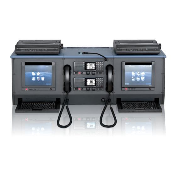
Chapter 1 Chapter 1: General information 1 General information Introduction With the System 6000 GMDSS console, all the communication equipment of the ship can be combined in one small, compact console. One of the main purposes of the console is to make the best possible use of the limited space on board a ship. Further- more, the fact that all the equipment is kept in the same place makes installation easy and fast. - Page 8 Introduction Chapter 1: General information 98-131571-B...
-
Page 9: Chapter 2 Installation
Chapter 2 2 Installation Dimensions Console type numbers and part numbers refer to console hardware only, i.e. an empty console with only dimable light and connection board(s) installed. Equipment illustrated for reference only. Type 6334C 1645mm 380mm 2 pcs. SAILOR 630x MF/HF Control Unit 3 pcs. - Page 10 Dimensions Type 6334B 1 pcs. SAILOR 630x MF/HF Control Unit 1 pcs. SAILOR 62xx VHF Radio 1445mm 380mm 2 pcs. SAILOR H1252B USB/Parallel Printer 2 pcs. SAILOR 6006 Message Terminal MF/HF 1 pcs. TT-3670 IP Handset Mini-C Mini-C Weight: excl. units 50 kg incl. units 71 kg 99-132162...
-
Page 11: Drilling And Cutting Template
Drilling and cutting template Type 6330 SAILOR 6330 Console connection box Drilling and cutting template The console can be placed and mounted, in several different ways, to ensure optimal integration into the user environment. 2.2.1 Tabletop mounting for 2 x 400mm section Drilling template for 400mm section. -
Page 12: Tabletop Mounting For 3 X 400Mm Section
Drilling and cutting template 2.2.2 Tabletop mounting for 3 x 400mm section Drilling template for 400mm section. Cut for cable entry Cut for cable entry Cut for cable entry 4 mounting holes (ø6) 4 mounting holes (ø6) 4 mounting holes (ø6) NB! The table must be sufficiently supported to carry the console. -
Page 13: Bulkhead Mounting For 3 X 400Mm Section
Drilling and cutting template 2.2.4 Bulkhead mounting for 3 x 400mm section Drilling template for 400mm section. Earth stubs entry. Earth stubs entry. Earth stubs entry. 99-132409 To avoid vibration noise, the console should be fastened with screws onto the bulkhead. ** Space from last left- and righthand section to wall. (22.5 + spacing = 25mm) 2.2.5 Earth stubs mounting Earth stubs entry. -
Page 14: Placement Of Connection Boards And Moxa Switches
Mounting the console onto the bulkhead 2.2.6 Placement of connection boards and moxa switches Connection Board (1) Moxa switches Connection Board (2) (1) (2) Earth stubs entry. Earth stubs entry. Earth stubs entry. 99-132542 Mounting the console onto the bulkhead When the console is placed on a table, the back of the console can be attached onto the bulkhead. This allows for free access to the connection board and wiring while installing. 1 Remove the rear (back cover) panels, by removing all 6 screws in each panel. - Page 15 Mounting the console onto the bulkhead Remove all key-hole screws from the back. Using a hacksaw, cut away the back part, of the bottom plate, by following the pre-cut lines. Do this on sections, where connection boards are fitted. 6 Mount all key-hole screws, from the inside of the console. 98-131571-B Chapter 2: Installation...
- Page 16 Mounting the console onto the bulkhead Fasten the console to the bulkhead, with 2 screws per section. Loosen key-hole screws and lift up the front part. Lift here At this point connection board wiring may be done while having free access to the connection boards. 10 Fit the front part back onto the key-hole screws. 11 Fasten key-hole screws. Fasten the console to the table, with four screws per section Reinstall the plate, removed in step 3.
-
Page 17: Paper Roll
Control Units Paper roll Clearance required above console to open top for access to printer paper roll. 99-133321 Control units 98-131571-B Chapter 2: Installation... -
Page 18: Message Terminal
Message Terminal Message Terminal Power Converter Install the SAILOR 6090 Power Converter on the dividing support frame in the console. Chapter 2: Installation 98-131571-B 2-10... -
Page 19: Factory Configuration Of The Console
Factory configuration of the console 2.8 Factory configuration of the console When the 6000 GMDSS Console system is ordered along with the relevant equipment sets and Service Pack part number (Service Pack denotes factory installation of units in console) the configuration of the equipment will be as per the following notation: In consoles with two handsets and hence two radio control units, the left side handset is always associated with the upper most control unit (MF/HF CU). Supplied with the Console accessory kit are self adhesive labels which may be used to mark the respective handsets for MF/HF and VHF, for ease of identification (Fig. 1). 1245mm MF/HF MF/HF 2 MF/HF Mini-C... - Page 20 Factory configuration of the console With one 6006 mini-C and the full MF/HF Radiotelex installed (Fig. 3) the MF/HF Control unit is installed as the upper most unit being part of System #1 or primary GMDSS equipment with associated Radiotelex Message terminal/keyboard and printer installed in the left hand side of the console. The #1 VHF is installed below the MF/HF Control Unit as part of the #1 System or primary GMDSS equipment. The 6006 mini-C is installed in the right hand side of the console being part of System #2 or duplication GMDSS equipment. The two Message Terminals (Fig. 3) are configured with the Radiotelex application software program and the Capsat application software program respectively. 1245mm 380mm Radiotelex printer Printer MF/HF Telex Mini-C 99-132163 Fig.
-
Page 21: Chapter 3 Electrical Installation
Chapter 3 3 Electrical installation Grounding cables Grounding of all external cable screens to the console is important in order to reduce risc of noise and inter- ference in the GMDSS installation. The screen of each external cable must be properly terminated to the support bracket by means of a cable lug properly secured to the support bracket with a screw. 99-127906 All internal cable screens are grounded to the support bracket using tie wraps. 99-127907 98-131571-B Chapter 2: Electrical Installation... -
Page 22: Console Light
Console light Console light The intention is to supply the console workplace, with sufficient ambient light for working. If desired, the light can be turned off completely, so that it does not distract the ship operator, for example during night time. However when required the light can be turned on quickly, by means of a switch. By turning the dimming potentiometer clockwise, the light intensity increases, and correspondingly turning the potentiometer counter clockwise decreases the light intensity. The light can be switched off, by turning the potentiometer fully counter clockwise past the click. The gooseneck lamp is fed by a regulated DC voltage. The max. voltage supplied to the gooseneck lamp is around 12VDC. The gooseneck lamp comprise a 3 pin XLR-plug with a release button. Pin 2 carries positive supply voltage (+), pin 3 is connected to DC-. Pin 1 is not connected. The gooseneck lamp supplied with the console is of the type providing white light. A gooseneck lamp of red light type is available from the Thrane & Thrane eShop identified as P/N S-29-127565-A. -
Page 23: Connection Board
Connection board Connection board The connectors on the Connection board are grouped in relation to products. Each connector has been given a unique name and designator in order to clearly identify the connector. Also where the wires are mounted into terminal strips, each connection has been named. The first digit of a designa- tor, is a consecutive number, and the second digit is a digit only used for connections belonging to that group. Every designator starts with a „J“, to indicate that this is a type of connector. For example, the first connector for VHF connection carries the designator „J20“, the second connector „J21“... -
Page 24: Schematic Connection Board
Scematic connection board Schematic connection board Chapter 3: Electrical Installation 98-131571-B... -
Page 25: Mf/Hf Can-Bus Termination
MF/HF CAN-bus termination MF/HF CAN-bus termination The jumper W1 terminates the MF/HF CAN-bus. If an external CU is connected to the console connection board and the cable is more than 6 m long, remove the jumper W1. The termination must then be connected to the CU at the most distant point from the transceiver. -
Page 26: Mini-C Can-Bus Termination
mini-C CAN-bus termination mini-C CAN-bus termination In case the mini-C CAN-bus is to be terminated in the console, i.e. no TCU (6194) connected install inline termination connector at J41. Inline Micro termination connector is available from Thrane & Thrane, identified as P/N 406100-932. Chapter 3: Electrical Installation 98-131571-B... -
Page 27: Chapter 4 Installation Cables
Chapter 4 4 Installation cables Console wiring system The internal wiring of the console has been grouped and numbered in the following drawings, so that each cable is easily identified by its unique identifier. Numbering The numbering is grouped in three digits, as indicated below. The type of signal carried is also indicated in the table listing the internal cables. -
Page 28: Internal Cable Overview
C9.3.17 Cable, 4 pole Light Control 37-126772 DC supply C9.3.18 Cable, 2 pole Light / Gooseneck 37-126773 DC supply C9.3.19 Power Cable SAILOR 6197 Switch 37-131395 DC supply Additional cables can be ordered at Cobham SATCOM eshop. Chapter 4: Installation cables 98-131571-B... -
Page 29: Internal Cables 4 Section Console W/2 X Mf/Hf Radiotelex And Mini-C
Internal cable overview 4.2.1 Internal cables 4 section console w/2 x MF/HF Radiotelex and mini-C (sea area A4) 98-131571-B Chapter 4: Installation cables... -
Page 30: Internal Cables 3 Section Console W/Mf/Hf Radiotelex, Mini-C And Vhf
Internal cable overview 4.2.2 Internal cables 3 section console w/MF/HF Radiotelex, mini-C and VHF Chapter 4: Installation cables 98-131571-B... -
Page 31: Internal Cables 3 Section Console W/ Mf/Hf, 2 X Mini-C And Vhf
Internal cable overview 4.2.3 Internal cables 3 section console w/ MF/HF, 2 x mini-C and VHF 98-131571-B Chapter 4: Installation cables... - Page 32 Internal cable overview 4.2.4 Internal cables 2 section console w/ MF/HF Radio Telex and VHF C7.2.11 Light Printer Light Control C7.2.05 C7.2.04 NMEA LIGHT Thrane & Thrane 38-130999-F Ext. CU Gooseneck 0183 TEST VHF & MF/HF 1 SHLD 1 24VDC+ 2 GND Dimmer 1 NMEA+...
-
Page 33: Internal Cables 1 Section Console W/ Mf/Hf And Vhf
Internal cable overview 4.2.5 Internal cables 1 section console w/ MF/HF and VHF Light Light Control C7.2.05 C7.2.04 NMEA LIGHT Thrane & Thrane 38-130999-F Ext. CU Gooseneck 0183 TEST VHF & MF/HF 1 SHLD 1 24VDC+ 2 GND Dimmer 1 NMEA+ 2 24VDC- 3 +24V 2 NMEA-... -
Page 34: External Cabling
External cabling External cabling 4.3.1 External cabling - Light, Ethernet switch and position source SAILOR 6081 (Optional up to 3 additional 6080) Power Supply & Charger Power Supply Position source NMEA LIGHT Thrane & Thrane 38-130999-F Ext. CU Gooseneck 0183 24V DC+ TEST NMEA+... -
Page 35: External Cabling - Vhf
External cabling 4.3.2 External cabling - VHF Connection CU - AUX Connector Board J21 LTW 12 pin Description Wire color VDR+ Mixed Rx/Tx for record Violet VDR- Mixed Rx/Tx for record Cyan AUX 0C Yellow DSC Call Grey DSC Alarm Pink -Battery External Speaker + Black... -
Page 36: External Cabling - Mf/Hf
External cabling 4.3.3 External cabling - MF/HF Connection Connection Connection CU - AUX Connector Wire Board J36 Board J33 Board J70 LTW 10 pin Description color NMEA+ Brown SAILOR 630x MF/HF Control Unit NMEA- Blue 2182 Select White Green Yellow Ext. -
Page 37: External Cabling - Mini-C And Power Supply
SAILOR 6081 (Optional up to 3 x 6080) Power Supply & Charger Power Supply & Charger 99-132824-B For further installation details, please refer to individual product manuals and cable plans available for download at the Cobham SATCOM extranet. 98-131571-B Chapter 4: Installation cables 4-11... - Page 38 External cabling 4-12 Chapter 4: Installation cables 98-131571-B...
- Page 40 98-131571-B www.cobham.com/satcom...
Need help?
Do you have a question about the SAILOR 6000 and is the answer not in the manual?
Questions and answers