COBHAM SAILOR 100 GX Installation Manual
Hide thumbs
Also See for SAILOR 100 GX:
- Installation manual (207 pages) ,
- Technical manual (252 pages) ,
- Installation manual (6 pages)

Related Manuals for COBHAM SAILOR 100 GX


Summary of Contents for COBHAM SAILOR 100 GX
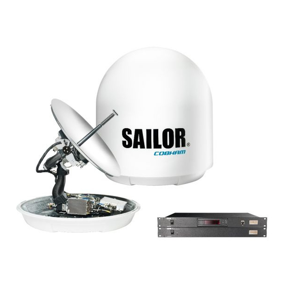
- Page 1 SAILOR 100 GX SAILOR 100 GX High Power SAILOR 100 GX-R2, 4.5 W and 9.0 W Installation manual COBHAM PUBLIC...
- Page 2 This gives you temporary administrator access for 1 hour or until next restart 4. Open an Internet browser to access the web interface of the SAILOR 100 GX: IP address: http://192.168.0.1. (default on LAN Port 3), user name: admin, password: leave empty or type in new (minimum 8 characters).
- Page 3 SAILOR 100 GX including SAILOR 100 GX High Power, GX-R2 4.5W and GX-R2 9.0W Installation manual Document number: 98-141779-G Release date: 16 February 2021...
- Page 4 SW Technology/GPL Compliance, Cobham SATCOM (Thrane & Thrane A/S), Lundtoftegaardsvej 93D 2800 Lyngby DENMARK Write "source for product SAILOR 100 GX" in the memo line of your payment. This offer is valid to anyone in receipt of this information. http://www.cobham.com/communications-and-connectivity/satcom/free-and-open-source-software- foss/ 98-141779-G...
- Page 5 Deck Unit’s mounting plane. Refer to the drawing below. Safety distance: SAILOR 100 GX and SAILOR 100 GX-R2 4.5W: 30 m, 10 W/m SAILOR 100 GX High Power and SAILOR 100 GX-R2 9.0W: 44 m, 10 W/m MICROWAVE RADIATION No personnel within safety distance 98-141779-G...
- Page 6 ACU and Above Deck Unit can be extended if it complies with the specified data concerning cable losses etc. Rx and Tx cables for the SAILOR 100 GX system are shielded and should not be affected by magnetic fields. However, try to avoid running cables parallel to high power and AC/RF wiring as this might cause malfunction of the equipment.
- Page 7 Record of Revisions Rev. Description Release Date Initials Original document 22 September 2014 The following sections have been edited: Quick guide, 3.3.4, 5.3.2, 6.1.2, 6.2.1, 6.2.3, 6.2.5, App. D 15 December 2014 The following figures have been edited: 6-3, 6-5, 6-14, 6-18 The following tables have been edited: 6-1, 6-8, 6-14, 6-19, 7-3 The following sections have been added: 3.5.3, 3.6.1, 4.1.2, 6.2, 8.1.2, 8.1.3, 8.1.4, 8.8...
-
Page 8: Table Of Contents
About this manual Intended readers ......................1-1 Manual overview .......................1-1 Software version .......................1-2 Typography ...........................1-2 Precautions ..........................1-2 Chapter 2 Introduction SAILOR 100 GX system ....................2-1 2.1.1 Overview ..........................2-1 2.1.2 Above Deck Unit (ADU) ....................2-3 2.1.3 Antenna Control Unit (ACU) ..................2-8 2.1.4 GX Modem Unit (modem) ....................2-9... - Page 9 I/O connector for Tx Mute and Rx Lock (future use) ........4-8 Chapter 5 Power and start up Power-up procedure .......................5-1 5.1.1 Initialisation steps in daily use ..................5-2 5.1.2 SAILOR 100 GX operational ...................5-2 Chapter 6 Configuration Introduction to the built-in web interface ..........6-1 6.1.1 Overview ..........................6-1 6.1.2 Connecting to the web interface ................6-1...
- Page 10 Table of contents Heading input and position system ..............6-4 Calibration ..........................6-8 6.3.1 Azimuth calibration ......................6-8 6.3.2 Service profile for calibration ..................6-11 6.3.3 Cable calibration .......................6-12 6.3.4 Manual OTC (BUC calibration) and GX modem access ......... 6-13 Operation in gyro-free mode ................6-16 6.3.5 6.3.6 Fixed TX IF principle .......................
- Page 11 8.8.2 The questions ........................8-21 To return units for repair ..................8-32 Appendix A Technical specifications SAILOR 100 GX specifications ................A-2 SAILOR 100 GX-R2 4.5W or 9.0W specifications ........A-4 Patents ............................A-5 Outline drawings .......................A-6 A.4.1 ADU ............................A-6 A.4.2 ACU ............................A-7 A.4.3...
- Page 12 Table of contents Appendix C Ground and RF protection Why is a ground connection required? ............C-1 C.1.1 Safety ............................C-1 C.1.2 ESD Protection ........................C-1 Recommendations ......................C-1 C.2.1 To ground the ACU ......................C-1 C.2.2 To ground the ADU ......................C-3 Alternative ground for steel hulls ................C-4 C.3.1 To ground the ACU ......................C-4 C.3.2...
- Page 13 ............................E-8 E.2.9 system ............................E-8 E.2.10 track ............................E-9 E.2.11 zone ............................E-10 Appendix F Approvals CE (RED) ........................... F-1 Inmarsat SAILOR 100 GX ADS ................F-3 Japan approval (SAILOR 100 GX) ................. F-4 Glossary ................................Glossary-1 Index ..................................Index-1 98-141779-G...
-
Page 14: Chapter 1 About This Manual
407090G-00500 SAILOR 100 GX High Power 407090K-00500 SAILOR 100 GX-R2 4.5W 407090L-00500 SAILOR 100 GX-R2 9.0W The term SAILOR 100 GX is used in general. If necessary, the explicit names are used. 1.2 Manual overview This manual has the following chapters: •... -
Page 15: Software Version
Software version 1.3 Software version This manual is intended for SAILOR 100 GX with software version 1.64 (ADU and ACU). 1.4 Typography In this manual, typography is used as indicated below: Bold is used for the following purposes: • To emphasize words. -
Page 16: Introduction
2.1 SAILOR 100 GX system 2.1.1 Overview The SAILOR 100 GX is a unique stabilized maritime GX antenna system operating in the Ka- band (19.2 to 30 GHz). It is used with the Global Xpress service from Inmarsat, delivering consistent high-performance download speeds of up to 50 Mbps and 5 Mbps over the uplink. - Page 17 SAILOR 100 GX system Above Deck Unit (ADU) Antenna Control Unit (ACU) GX Modem Unit (GMU) Figure 2-2: ADU, ACU and GMU 2.1.1.1 SAILOR 100 GX features Single 50 Ohm coax cable between ADU and below deck equipment. One-Touch Commissioning. ...
-
Page 18: Above Deck Unit (Adu)
SAILOR 100 GX system 2.1.2 Above Deck Unit (ADU) The SAILOR 100 GX ADU is a 103 cm stabilized tracking antenna, consisting of a suspended antenna with a standard global RF configuration. It is stabilized by heavy duty vibration dampers in 3-axi (plus skew)s and can be used in environments with elevations of -25° to + 125°. - Page 19 SAILOR 100 GX system 2.1.2.1 Modules in the SAILOR 100 GX ADU Figure 2-4: Above Deck Unit modules 1/2 1. GNSS module. 2. VSAT Interface Module (VIM). 3. Pedestal Control Module (PCM). 4. Service switch. In switch-off position the Motor Driver modules and the BUC are turned off for safe conditions during service and repair.
- Page 20 SAILOR 100 GX system 7. Zero Reference Module (x3) (ZRM) (not visible on photo), (2 in the figure above, 1 in the figure below). 8. Motor Driver Module for elevation (on the bottom) (DDM/SMD). 9. Elevation motor and encoder (not visible).
- Page 21 SAILOR 100 GX system 2.1.2.2 Modules in the SAILOR 100 GX-R2 ADU Figure 2-6: Above Deck Unit modules 1/2 1. GNSS module. 2. VSAT Interface Module (VIM). 3. Pedestal Control Module (PCM). 4. Service switch. In switch-off position the Motor Driver modules is turned off for safe conditions during service and repair.
- Page 22 SAILOR 100 GX system 10. BUC Control Module (BCM). 11. GX-R2 Transceiver. 12. Inertial Sensor Module (ISM). 13. Elevation locking pin to lock the antenna dish in a fixed position. Figure 2-7: Above Deck Unit modules 2/2 14. Motor Driver Module for Azimuth (DDM/SMD).
-
Page 23: Antenna Control Unit (Acu)
SAILOR 100 GX system hatch on site. The ADU software is updated automatically when you make a software update of the ACU. 2.1.3 Antenna Control Unit (ACU) The ACU is the central control unit in the system. It contains all user interfaces and manages all communication between the ADU and the connected modem, a connected PC and an optional FleetBroadband service communication line. -
Page 24: Gx Modem Unit (Modem)
For a list of satellite type approvals see Appendix F, Approvals. 2.1.6 Service activation Before you can start using the SAILOR 100 GX, you need to activate the system for the GX service. Contact your service provider for activation. 98-141779-G... -
Page 25: Part Numbers And Options
Part numbers and options 2.2 Part numbers and options The following model and part numbers are available for the SAILOR 100 GX system: Part number Description 407009C-00501 Above Deck Unit (ADU) 407009G-00500 Above Deck Unit, High Power 407009K-00500 Above Deck Unit, GX-R2 4.5W 407009L-00500 Above Deck Unit, GX-R2 9.0W... -
Page 26: Chapter 3 Installation
Chapter 3 Installation This chapter has the following sections: • What’s in the box • Site preparation • Installation of the ADU • Installation of the ACU • Installation of the modem • To connect the ADU, ACU and modem 3.1 What’s in the box 3.1.1 To unpack Unpack the modem, ADUand ACU. -
Page 27: Tools Needed
What’s in the box WARNING! To avoid electric shock, do not apply power to the system if there is any sign of shipping damage to any part of the front or rear panel or the outer cover. Read the safety summary at the front of this manual before installing or operating the system. -
Page 28: Site Preparation
1. Mount the ADU on stiffened structures with a minimum of exposure to vibrations. You do not have to align the ADU with the bow-to-stern line of the ship. When configuring the SAILOR 100 GX system, the azimuth calibration provides the correct azimuth of the ADU. -
Page 29: Obstructions (Adu Shadowing)
Site preparation Cobham SATCOM recommends that the radome should NOT be modified or changed to another type. Exchanging or modifying the radome will not void the general warranty for material and workmanship etc. but the performance cannot be guaranteed, and the satellite operator approvals will not be valid. -
Page 30: Blocking Zones With Azimuth And Elevation
Site preparation 3.2.3 Blocking zones with azimuth and elevation Your installation may require that you set up blocking zones for the ADU, i.e. areas where the ADU will not transmit and areas where transmit power is potentially dangerous for persons frequently being in these zones. You can set up 8 blocking zones. Each blocking zone is set up with azimuth start and stop, and elevation angle. -
Page 31: Safe Access To The Adu (Radiation Hazard)
Site preparation 3.2.4 Safe access to the ADU (radiation hazard) The ADU radiates up to 53.5 dBW EIRP, for High Power 56.6 dBW EIRP at 29.5 GHz.This translates to a minimum safety distance of 30 m, for High Power 55 m, from the ADU while it is transmitting, based on a radiation level of 10 W/m MICROWAVE RADIATION NO PERSONNEL within safety... -
Page 32: Adu Mast Design: Mast Foundation And Height
Site preparation Even though it is recommended to mount the ADU high, keep the distance between the ADU and the ship’s motion centre as short as possible. Maximum antenna mounting height (h max) Min. roll period Full performance Potential risk of damage 12 m (39 ft) 16 m (53 ft) 27 m (89 ft) - Page 33 Site preparation 3.2.6.1 ADU mast flange For best performance provide a mast flange with a minimum of four gusset plates. To prepare the mast flange do as follows: 1. Fit the top of the ADU mast with a flange with clearance holes matching the bushings in the radome and with minimum 4 gusset plates.
- Page 34 Site preparation 3. Allow sufficient space so the nut is free of the welded seam and there is room for tools (min. 50 mm). Clearance hole for M12 bolts Figure 3-8: ADU mast flange, distance to the welded seam 4. Use the dimensions in the following figure to prepare the mast flange for mounting of the ADU.
- Page 35 Site preparation Free mast length Figure 3-10: Free mast length and example bracing for a tall mast Make sure that there is free space below the drain tube. See also Condensation, Note water intrusion and deposits on page 3-15. The tables in the next sections give suggested design values for the free mast length. The tables list the values for steel masts.
- Page 36 Site preparation Outer Max. free Outer Wall Thickness Diameter Mast with 3 braces mast length Diameter Thickness for brace for brace (steel), (m) (mm) (mm) (mm) (mm) 30-40° Table 3-3: Mast dimensions with 3 braces Max. free Outer Thickness Outer Wall mast Diameter...
-
Page 37: Interference From Radar, Gps, L-Band And Other Transmitters
Due to near field effects the benefit of this vertical separation could be reduced at short distances (below approximately 10 m) between radar antenna and the SAILOR 100 GX ADU. 2. Provide as much vertical separation as possible when the SAILOR 100 GX ADU has to be placed close to a radar antenna. Radar Min. - Page 38 Even at distances greater than “d min.” in the previous section the radar might still be able to degrade the performance of the SAILOR 100 GX system. The presence of one or more S or X-band radars within a radius up to 100 m may cause a minor degradation of the Ka- band connection.
- Page 39 3.2.7.5 L-band antennas If L-band antennas are installed on the same vessel, keep a minimum distance of 3 meters from the SAILOR 100 GX ADU to the L-band antenna. 3.2.7.6 Other transmitters See the following figure for minimum recommended distance to transmitters in the frequency range below 1000 MHz.
-
Page 40: Condensation, Water Intrusion And Deposits
Site preparation 3.2.8 Condensation, water intrusion and deposits In some weather conditions there may occur condensation inside the radome. The drain tube is designed to lead any water away from inside the radome. Observe the following guidelines for condensation and water intrusion: 1. -
Page 41: Installation Of The Adu
Installation of the ADU 3.3 Installation of the ADU 3.3.1 Prerequisites • Ensure that the crane hook has a closing mechanism to prevent accidental slippage of the lifting straps. • Check for potential interference, read more in Interference from radar, GPS, L-band and other transmitters on page 3-12. -
Page 42: To Install The Adu
Installation of the ADU 3.3.3 To install the ADU 3.3.3.1 Prerequisites • Make sure that there is sufficient space underneath the ADU to open the service hatch. Through this hatch you access the ADU modules for service and maintenance. Figure 3-15: Free space for access to the service hatch •... - Page 43 Installation of the ADU Figure 3-16: ADU installation, webbed sling attached to the 4 lifting brackets 5. Attach two tag lines of suitable length to 2 lifting brackets and man them. 6. With a crane lift the ADU off the wooden platform and move it on top of the mast. Maintain vertical orientation of the ADU center line.
- Page 44 Installation of the ADU Figure 3-17: Mounting the ADU on the mast flange 9. Attach the N connector of the ADU cable to the ADU and fasten it with 2.5 Nm N connector Figure 3-18: Connecting the ADU cable 10. Ensure that the connector assembly is properly protected against seawater and corrosion.
-
Page 45: To Open The Service Hatch
Installation of the ADU 3.3.4 To open the service hatch Through the service hatch you can access the antenna modules. You can remove the hatch for better mobility when servicing the antenna. Figure 3-19: To open the service hatch To open the service hatch in order to access the antenna modules do as follows : 1. -
Page 46: Alternative Adu Cable
Installation of the ADU Figure 3-20: ADU, thread for optimum grounding If the ADU cannot or should not be electrically connected directly to the mounting surface, you can use a separate grounding cable to make the connection between the ADU and the common ground to which the ACU is also connected. - Page 47 Installation of the ADU Cable type Thickness Absolute max. length (m) Absolute max. length (ft) LMR-600-50 1/2” 150 m 490 ft LDF4.5-50 Andrew 5/8” 270 m 810 ft Table 3-7: ADU cable types and maximum lengths (Continued) If you want to use an alternative ADU cable make sure that the following requirements are fulfilled: 1.
-
Page 48: Installation Of The Acu
Installation of the ACU 3.4 Installation of the ACU The following sections describe the installation and grounding of the ACU. 3.4.1 To install the ACU To install the ACU, do as follows: 1. Slide the ACU into a 1U space in a 19” rack. 2. -
Page 49: Installation Of The Modem
Installation of the modem 3.5 Installation of the modem The following sections describe the installation and how to ground the modem. 3.5.1 To install the modem To install the modem, do as follows: 1. Slide the modem into a 1U space in a 19” rack, preferably directly below or above the ACU. -
Page 50: To Connect The Adu, Acu And Modem
To connect the ADU, ACU and modem Model: TT–7023A Prod.:YYYY/WW SAILOR GX Modem Unit P/N 407023A-T19 S/N: xxxxxxxxxx Rev.: X.XX Provisioning Key: CQACJAIFGYQ54=== Terminal Type: TNT-MAR-SCM-1000300 Compass Safe Distance: 0.4m Thrane & Thrane A/S, Denmark Figure 3-23: Provisioning key and terminal type (example) 3.6 To connect the ADU, ACU and modem The following sections show how to connect the ADU, ACU and the modem. - Page 51 To connect the ADU, ACU and modem 3-26 Chapter 3: Installation 98-141779-G...
-
Page 52: Interfaces Of The Acu
Chapter 4 Interfaces This chapter has the following sections: • Interfaces of the ACU • Interfaces of the modem 4.1 Interfaces of the ACU 4.1.1 LEDs, display, keypad and connectors The following figure shows the LEDs, display and the keypad of the ACU. For an explanation of the texts in the display see ACU display and keypad on page 6-38. -
Page 53: Ac Input Connector
Interfaces of the ACU 4.1.2 AC input connector Connect the power cable to the AC power connector. Outline (on the ACU) Voltage range 100–240 VAC Earth Table 4-1: AC power connector 4.1.3 ADU connector The coax cable from the ACU to the ADU is used to power the ADU, supply a reference clock, handle all communication between ACU and ADU, and deliver the Rx and Tx signals. -
Page 54: Nmea 0183 Connector
Interfaces of the ACU 4.1.5 NMEA 0183 connector Outline (on the ACU) Pin function Wire color Not connected – NET-H (NMEA 2000) White NET-L (NMEA 2000) Blue NET-S (NMEA 2000) NET-C (NMEA 2000) Black Not connected – RS-232 RX (NMEA 0183) –... -
Page 55: And Rs-422 Connectors
Interfaces of the ACU 4.1.6 RS-232 and RS-422 connectors The ACU has an RS-232 and RS-422 connector. They are used for GX modem control). Outline (on the ACU) Pin function Not connected Ground Receive Signal Strength Indicator Table 4-5: RS-232 connector, male, outline and pin assignment, ACU Outline (on the ACU) Pin function Ground... -
Page 56: Lan1 - 4 Connectors
LAN connector of the ACU for system control. 4. Use Port 4 (network 3) to connect the SAILOR 100 GX to the vessel’s LAN. For more details about the LAN networks see To configure the LAN network on page 6-24. -
Page 57: Interfaces Of The Modem
Interfaces of the modem 4.2 Interfaces of the modem The following sections describe the connectors of the modem and how to connect to the ACU, power and other equipment. 4.2.1 Connector panel The following figure shows the connector panel of the modem. Tx Mute &... -
Page 58: And Rs-422 Connectors
Interfaces of the modem 4.2.3 RS-232 and RS-422 connectors The modem has two RS-232 and one RS-422 connector for control information to and from the ACU. See section To connect the ADU, ACU and modem on page 3-25 for details how to connect the ACU to the modem. -
Page 59: Lan Connectors (8 + 2)
Interfaces of the modem 4.2.4 LAN connectors (8 + 2) The modem has 8 Ethernet connectors (type RJ45). Port 1 connects to the ACU and is used for modem control. The other ports are not used. The maximum cable length per connection is 100 m. -
Page 60: Power And Start Up
• READY This may take some time (up to a couple of minutes). 3. The SAILOR 100 GX is ready to be calibrated (for first time power up) or receive data from the modem (when in normal operation). The LEDs Power and Fail/Pass are steady green, the LED Logon is off. For further information on status indicators see Status signalling with LEDs and status messages on page 8-16. -
Page 61: Initialisation Steps In Daily Use
• Antenna POST • READY • POINTING ANTENNA • ACQUIRING SIGNAL • TRACKING 5.1.2 SAILOR 100 GX operational When the display shows TRACKING. MDM: NETOK and the LED Logon is steady green the system is operational. Main NAV:GH MDM: NETOK LAN: 1 –... -
Page 62: Configuration
6.1 Introduction to the built-in web interface 6.1.1 Overview With the built-in web interface of the SAILOR 100 GX ACU you make a full configuration of the SAILOR 100 GX. You can use a standard Internet browser. Installation of software is not necessary. - Page 63 3: Service port 4: Ship’s network Figure 6-1: LAN 3 connector used for configuration of the SAILOR 100 GX If you want to use another LAN port to access the web interface you must configure it as described in To configure the LAN network on page 6-24.
- Page 64 Introduction to the built-in web interface 6. Type in the new password (minimum 8 characters) and click Change. No old password is required. After 1 hour or a restart the new administrator password is required. With the guest login (user name: guest, password: configured by the administrator) you can protect the system from accidental changes of the configuration.
-
Page 65: Heading Input And Position System
Make sure that the modem is switched off at this point. Switch on the Important modem after the cable calibration. Before the SAILOR 100 GX can be used you must select the heading input and the positioning system. You must be logged on as an administrator. See Administration on page 6-33. - Page 66 GPS source is required. 5. For GNSS System, select from GPS, Beidou, GPS and Beidou, GPS and GLONASS. The SAILOR 100 GX uses GPS by default 6. For Manual enter the latitude, longitude and altitude. 7. Click Apply.
- Page 67 Heading input and position system If the external GPS input is lost or GPS invalid the ACU will fall back to built-in GNSS but generate following warning message: 8084-0 Terminal WARNING External GPS data (00000041) About the acquisition process and search pattern With heading input or fixed heading 1.
- Page 68 Heading input and position system Acquisition time Activity Initial search 10 s Scan box pattern Validate result (10 s per 10 - 30 s result) Max. total time 25 - 45 s Table 6-2: Acquisition time 98-141779-G Chapter 6: Configuration...
-
Page 69: Calibration
Service profile to be used for the azimuth calibration. A cable calibration is required in order to record the cable characteristics of the antenna cable which is used in the SAILOR 100 GX fixed gain feature. See Fixed TX IF principle on page 6-16 for more information. After the calibration you can set up blocking zones for the specific installation. - Page 70 Calibration Satellite Position Frequency Satellite identifier GX1 –IOR 62.6 E 19.707 GHz GSC GX2 –AOR 55 W 19.707 GHz GSC GX3 –POR 179.6 E 19.707 GHz GSC GX4 –IOR 56.6 E 19.707 GHz GSC GX5 –EME 11.0 E 19.701 GHz GSC Table 6-3: Inmarsat GSC satellite information The calibration function is not able to verify the correctness or precision of Important...
- Page 71 Calibration Error code Explanation No signal received. Check that there is free line of sight. Try again or try with another satellite. RF setup error, e.g. missing or invalid TX frequency. Invalid satellite, e.g. satellite not visible. Unknown error Table 6-4: Possible error codes during calibration (Continued) Automatic azimuth calibration with an active satellite profile You can enable automatic azimuth calibration, even if there is no line of sight to an azimuth calibration satellite or GX service satellite from the place of installation.
-
Page 72: Service Profile For Calibration
Calibration 5. Select Enable in the section Azimuth calibration (active satellite profile). To be able to use this feature there must be a valid satellite profile and you must activate it in SETTINGS > Satellite profiles. 6. Click Apply. 7. Switch on the modem. Azimuth calibration with a service profile 1. -
Page 73: Cable Calibration
Calibration Figure 6-8: Service profile for calibration 6. Enter the data for the satellite that you want to use as a calibration reference. Note the following calibration requirements: Elevation angle: 5 – 70 degrees. Not allowed for calibration: Inclined orbit. Satellite identifier: GSC, NID, Orbital position (DVB-S, DVB-S2) . -
Page 74: Manual Otc (Buc Calibration) And Gx Modem Access
Calibration Figure 6-9: Web interface: SERVICE, Calibration, cable attenuator margin 2. Wait for the calibration to finish. After finished calibration a message with the result of the calibration is displayed in the field Result.This screen shows how much attenuation margin is left for the antenna cable. This indicates whether the antenna cable and connectors are in good condition and well crimped. - Page 75 Calibration To make a manual OTC for the modem, do as follows: WARNING! For your safety: Active RF transmission may occur during an OTC procedure. Software updates may also occur, yet the system is in receive- only mode during such auto-updates. You must use the Internet browser Firefox.
- Page 76 Calibration 6. Click Start. One Touch Commissioning takes place. When commissioning is completed the antenna will search for the I5 satellite with the highest elevation. 7. The antenna will find the satellite and the modem will perform the necessary steps to enter the network (software upgrades, if available).
-
Page 77: Operation In Gyro-Free Mode
6.3.6 Fixed TX IF principle The SAILOR 100 GX uses a TX IF gain concept. After calibration it provides a fixed average gain from the TX-port of the ACU to the input of the BUC. Advantages of the fixed TX IF gain principle are: •... -
Page 78: Configuration With The Web Interface
Configuration with the web interface 6.4 Configuration with the web interface 6.4.1 Overview and dashboard Topics in the web interface The site map gives an overview over the existing menus, submenus and topics. You can click on each menu in the site map to go directly to the page or display the respective submenu. - Page 79 Configuration with the web interface The web interface has the following sections: Figure 6-14: Web interface: DASHBOARD of SAILOR GX (example) 1. The navigation pane holds the main menu. Clicking an item in the menu opens a sub- menu in the navigation pane or a new page in the contents section. 2.
- Page 80 Configuration with the web interface To navigate the web interface • To expand a menu, click the menu in the navigation pane. • To access status and settings, click the relevant subject in the navigation pane or click the relevant icon in the icon bar. The status or settings are displayed in the contents section.
- Page 81 28.05 GHz (system hardware) ACU part name, Antenna part Part names, serial numbers for ACU and ADU, software name, ACU serial number, version of the SAILOR 100 GX. Antenna serial number, Software version Table 6-6: Web interface, DASHBOARD, first section a.
- Page 82 Description BUC TX On or Off. Shows if the SAILOR 100 GX has enabled the BUC or not. It is the same TX ON/TX OFF as shown in the display of the ACU, see ACU display and keypad on page 6-38.
-
Page 83: To Set Up Blocking Zones (Rx And Tx)
Configuration with the web interface 6.4.2 To set up blocking zones (RX and TX) You can define blocking zones, i.e. No TX and RX zones by entering azimuth and elevation angles for each blocking zone. The system’s blocking map is built up over some weeks and shows where the actual blocking zones are. - Page 84 Configuration with the web interface 3. Enter start and stop azimuth values in degrees for the blocking zone. Values allowed: 0 to 360 degrees. Enter clockwise. 360° 000° 315° 45° Blocking zone: 270° 90° Antenna 315° - 45° 225° 135° 180°...
-
Page 85: To Configure The Lan Network
Configuration with the web interface Optimization of the blocking zones The blocking map is intended as a tool to optimise the blocking zones in order to reduce the antenna’s downtime. It shows the active blocking zones and an automatic evaluation of the antenna reception. - Page 86 Internet. It must be located behind a dedicated network security device such as a fire wall. If any ports of the SAILOR 100 GX are exposed to the Internet you must change the default passwords as anyone with access and malicious intent can render the SAILOR 100 GX inoperable.
- Page 87 Configuration with the web interface Make the necessary changes on this page and click Apply. Sections Preferred use NETWORK Host The host name is used for identifying the ACU in local networks and in name reports. The default host name is acu. You can change the name. Letters (a-z), digits (0-9) and hyphen (-) are allowed.
-
Page 88: E-Mail Setup
Configuration with the web interface static IP address. Then set the default gateway source to static and enter the IP address of the default gateway. To remove the default gateway set it to 0.0.0.0. Alternatively, if the DHCP server is able to provide a default gateway address and you have selected DHCP client above, then select the same LAN as your default gateway source. -
Page 89: Setup Of Reports, Syslog And Snmp Traps
Configuration with the web interface • STARTTLS can upgrade the connection to SSL or TLS, it is not dependent on a port as SMTPS. SSL and TLS connections are encrypted, just as HTTPS, the data of the connection cannot be (easily) read. 4. - Page 90 8-3. Statistics report SAILOR 100 GX can send a statistics report at fixed intervals through an external Internet connection. This report contains historical information from the SAILOR 100 GX up to 1 month. It contains statistics data for the selected intervals. The report is sent as a zipped attachment to an e-mail address.
- Page 91 Description ADU SN ADU serial number SW ver. Software version System type SAILOR 100 GX Table 6-11: Statistics report, header record (Continued) Parameter recorded Description UTC. (s) UTC in seconds and date format for the data set. UTC (YYYY-MM-DD hh:mm) RSSI.Av...
- Page 92 Configuration with the web interface Parameter recorded Description Pos Ok (%) Valid position, in percent of the sampling interval. VMU Connection (%) Link with modem, in percent of the sampling interval. Blocking (%) Ship in blocking zone, in percent of the sampling interval.
- Page 93 Configuration with the web interface Figure 6-23: Statistics report (example, MS Excel 2007) Remote syslog You can set up the antenna to send each syslog message to a syslog server to advise the system administrator of the current status of the antenna. To set up sending syslog messages to a syslog server, do as follows: 1.
- Page 94 Configuration with the web interface 6.4.6 Administration In this section of the web interface you can configure the following administrative settings: • To change the password and log out • To set up user permissions for guest login • To import and export a system configuration •...
-
Page 95: Administration
Configuration with the web interface To change the password and log out ADMINISTRATION and User login you can change the password for the On the page currently logged in user (admin) or you can log out. Figure 6-25: Web interface: ADMINISTRATION, change administrator logon and password To change the current password, do as follows: 1. - Page 96 2. Click Change. At the next logon the new password is required. To set up user permissions for guest login You can manage user access to certain functions of the SAILOR 100 GX. You can allow or deny users that are not administrators (user name: guest, password: configured by the administrator) to access certain functions and make these pages read-only.
- Page 97 Configuration with the web interface Figure 6-27: Web interface: ADMINISTRATION, User permissions Study this screen thoroughly and decide which actions in the SAILOR Important 100 GX system configuration guest users (user name: guest) can access. If you select No, the affected pages are read-only, guest users cannot change the settings.
- Page 98 Configuration with the web interface To import and export a system configuration If you need to reuse a configuration in another SAILOR 100 GX system, you can save the current configuration to a configuration file. This file can then be loaded into another SAILOR 100 GX or be used as backup.
-
Page 99: Keypad And Menus Of The Acu
LAN: 1 – 3 4 TRACKING Signal strength Figure 6-29: Display and keypad of the ACU (example) Current status of the SAILOR 100 GX: NOT READY (waiting for input from GNSS, e.g. GPS) ANTENNA INITIALIZING ANTENNA SW UPLOAD ANTENNA POST ERROR... -
Page 100: Navigating The Menus
Keypad and menus of the ACU 3. NAV: Navigational information First letter: G (Valid GPS signal received from the GPS module) or g (No valid GPS fix) Second letter: H (Valid ship heading data received from the ship’s gyro) or h (No valid heading data). - Page 101 DEFAULT GATEWAY Figure 6-30: Antenna Control Unit, menu tree Top-level menu Top-level menu Description MAIN View with current status of the SAILOR 100 GX. Example when logged on to the satellite: Main NAV:GH MDM: NETOK LAN: 1 – 3 4 TRACKING This view is displayed after a time out of 10 minutes.
- Page 102 Keypad and menus of the ACU Top-level menu Description SATELLITE Current satellite information. This information is selected using the web interface. EVENTS System events. Active events are shown as: X ACTIVE EVENTS in the MAIN display. Press OK to update the list. Table 6-14: Top-level menus of the ACU (Continued) Menu descriptions ANTENNA menu...
- Page 103 Current IP address for LAN 1 MASK 1 Current netmask for LAN 1 PORT 3 IP (LAN 3) Current IP address of the SAILOR 100 GX web interface (default: http://192.168.0.1) MASK 3 (LAN 3) Current netmask of the SAILOR 100 GX web interface (default: 255.255.255.0)
-
Page 104: Brightness Of The Display
Keypad and menus of the ACU SATELLITE menu Description LNB LO HIGH Current LNB Local Oscillator frequency, high band (GHz), selected in the satellite profile LNB LO LOW Current LNB Local Oscillator frequency, low band (GHz), selected in the satellite profile Table 6-18: SATELLITE menu of the ACU (Continued) EVENT menu Description... -
Page 105: Power-Cycle Of The Acu And Adu
Keypad and menus of the ACU 6.5.5 Power-cycle of the ACU and ADU To power cycle the ACU and ADU do the following: 1. Press and hold until the ACU display shuts down and the ACU and ADU reboots. Main NAV:GH MDM: NETOK LAN: 1 –... -
Page 106: Snmp Support
SNMP is always enabled on all Ethernet interfaces. The SNMP community string is public. The SAILOR 100 GX offers via SNMP most of the data that are available from the DASHBOARD web pages. Detailed documentation about supported OIDs can be found in the SAILOR 100 GX MIB file. -
Page 107: Chapter 7 Installation Check
Chapter 7 Installation check Now that you have installed the system, you can test it to verify it is ready for customer delivery. Follow the check lists below to test the system for proper operation. • Installation check list: Antenna •... - Page 108 Installation check list: Antenna Step Task Further information Done Check that the ADU is grounded correctly, See To ground the ADU on page 3-20 using the mounting bolts. and Ground and RF protection on page C-1. Table 7-1: Installation check list: Antenna (Continued) Chapter 7: Installation check 98-141779-G...
-
Page 109: Installation Check List: Acu, Modem, Connectors And Wiring
Installation check list: ACU, modem, connectors and wiring 7.2 Installation check list: ACU, modem, connectors and wiring Step Task Verification and further information Done Check that the grounding of the ACU is See To ground the ACU on page 3-23 and correctly, using the mounting bolts and Ground and RF protection on page C-1. -
Page 110: Installation Check List: Functional Test In Harbor
Installation check list: Functional test in harbor 7.3 Installation check list: Functional test in harbor Step Task Further information Done Check that the antenna is The logon LED in the ACU display must be steady green and the display must show: TRACKING. tracking the satellite Check in the web interface: DASHBOARD:... -
Page 111: Chapter 8 Service
Chapter 8 Service This chapter has the following sections: • To get support • Software update • Satellite profiles and modem profiles • Status signalling with LEDs and status messages, s • Removal and replacement of the ACU • Removal and replacement of ADU modules •... -
Page 112: To Get Support
3. Click the link Download MIB file to download the MIB file. 4. Click the link Legal notices to see the license text for the source code of the parts of the SAILOR 100 GX software that falls under free and open source software. Chapter 8: Service... - Page 113 To get support 8.1.1.2 To download diagnostics and statistics reports You can download a diagnostics report. This report contains information relevant for the service personnel during troubleshooting situations. It is also useful documentation of the current setup. The report contains all parameters set during configuration. You can add diagnostic log information from the modem and the BUC.
- Page 114 8.1.1.4 Self test You can start a self test of the SAILOR 100 GX ADU and ACU. The self test checks all vital parts of the antenna and ACU. You can restart the antenna or the terminal (ADU and ACU).
- Page 115 1. Click the menu item SERVICE. Self test 2. Click the menu item Warning! The SAILOR 100 GX will reboot to perform the self test. Important Rebooting the ACU will terminate all existing connections. Figure 8-3: Web interface: SERVICE, Self test 3.
-
Page 116: Reset To Factory Default And Clear Event History
Internet connection. 8.1.2 Reset to factory default and clear event history You can reset the SAILOR 100 GX ADU and ACU to factory default. A reset to factory default will delete all settings, including satellite and... -
Page 117: Reset To Factory Default - Gmu
To get support Figure 8-4: Web interface: ADMINISTRATION > Factory default, ADU and ACU To reset to factory default settings, do as follows: 1. Click the menu item ADMINISTRATION > Factory default. 2. Click Reset to factory default. Calibration data for azimuth and cable calibration are not reset during factory Note default. - Page 118 To get support To reset the GMU to factory default, do as follows: 1. Click the menu item SERVICE > Modem. Figure 8-5: Web interface: SERVICE > Modem, Factory default 2. Click Reset Modem. 3. To power cycle the GMU push the power switch. For details about Modem access configuration see Modem access configuration on page 6-15.
-
Page 119: Software Update
This is shown in the ACU display as ANTENNA SW UPLOAD. To make a software update, do as follows: 1. Power up the SAILOR 100 GX system, i.e. switch on the ACU. Wait until the ACU has finished initializing. 2. Connect a PC to LAN interface 3 (Service port, standard Ethernet) of the ACU or to the front LAN connector of the ACU. - Page 120 Software update Figure 8-7: Software update with the web interface 7. Click Browse... and locate the new software file. 8. Click Upload. Do not browse away from the upload page. This will terminate the Important upload process. Wait for the browser to reload automatically. 9.
- Page 121 Software update 6. Set the IP address of the PC to static: IP:192.168.0.2, Subnet: 255.255.255.0 7. Open an Internet browser and type http://192.168.0.1 (Default IP address of the ACU) Figure 8-9: Upload software to terminal (Safe mode) 8. Click Browse... and locate the software file. 9.
- Page 122 Software update Figure 8-10: Verifying software update 8.2.2.3 Software update (modem) The modem detects automatically whether a software upgrade is needed. If yes, software upgrade is done automatically via the satellite link. You can see the current software version in the GMU web interface. 8-12 Chapter 8: Service 98-141779-G...
-
Page 123: Satellite Profiles And Modem Profiles
Satellite profiles and modem profiles 8.3 Satellite profiles and modem profiles 8.3.1 Satellite profiles A satellite profile with the GX Modem is already set up at the factory. You may add a satellite profile with the generic modem for troubleshooting purposes. This is done on the page Satellite profiles. -
Page 124: Modem Profiles
Satellite profiles and modem profiles 3. Select a modem profile. The page automatically displays the parameters available for the selected modem profile. For instructions how to add a modem profile see Modem profile – New entry and Edit on page 8-14. 4. - Page 125 Satellite profiles and modem profiles Figure 8-14: Web interface: SETTINGS, Modem profile – supported modems 2. Fill in a modem profile name of your own choice. 3. Select one of the supported modems from the drop down list. Generic modem: If you have a modem that is not included in the list, select the generic modem.
-
Page 126: Status Signalling With Leds And Status Messages
For details on error messages after a POST or a self test see Event list on page 8-4. 8.4.2 Means of signalling The SAILOR 100 GX provides various methods for signalling the system status. LEDs on the front panel of the ACU are used to signal: •... -
Page 127: Leds In The Acu
Status signalling with LEDs and status messages 8.4.4 LEDs in the ACU The ACU has 3 LEDs: on the front panel: Power, Logon and Fail/Pass LED. Behaviour Description Power Steady green Power supply OK Steady red Power supply failure No power Logon Flashing Current status is displayed:... -
Page 128: Removal And Replacement Of The Acu
Removal and replacement of the ACU 8.5 Removal and replacement of the ACU There are no parts in the ACU that you can remove or replace. Contact your Cobham SATCOM service partner for further repair or replacement. 8.6 Removal and replacement of ADU modules All replacement of modules must be carried out by a Cobham SATCOM service partner. -
Page 129: Troubleshooting Basics
8.7 Troubleshooting basics 8.7.1 Overview This section describes an initial check of the primary functions of the SAILOR 100 GX system, and provides some guidelines for troubleshooting. Generally, if a fault occurs without any obvious reason, it is always recommended to observe the LEDs and the ACU display showing the active events. -
Page 130: Frequently Asked Questions
Frequently asked questions 8.8 Frequently asked questions 8.8.1 Overview The following sections are a collection of frequently asked questions with answers. • Q1: What is OTC and what happens? • Q2: The antenna points towards the wrong Inmarsat GX satellite, what do I do? •... -
Page 131: The Questions
Frequently asked questions 8.8.2 The questions 8.8.2.1 Q1: What is OTC and what happens? OTC stands for One Touch Commission. OTC is similar to a P1dB compression test for VSAT but on multiple frequencies. The GMU will instruct the antenna to point away from the Clark belt (geostationary satellites), disable the Power Amplifier (PA) of the BUC and use a built-in Power Detector to measure the gain of the system from GMU tx-connector up to BUC PA. - Page 132 Frequently asked questions 8.8.2.4 Q4: How do I start a manual OTC procedure? You start a manual OTC procedure from the web server of the GMU. The GMU (iDirect Core Module) does NOT support Internet Explorer, use Mozilla Firefox or Chrome! 1.
- Page 133 Frequently asked questions 8.8.2.8 Q8: How do I log in to the GMU Linux shell? Make an SSH connection (Freeware: PuTTY.exe) to the ACU on IP port number 8022. Example: ssh 192.168.0.1:8022 User and Password: root / iDirect or root / iDirect123! 8.8.2.9 Q9: ACU stays in BUC CALIBRATION state almost forever, what can I do? Make a new manual OTC and wait until the GMU reboots and sends a new pointing request to the ACU.
- Page 134 Frequently asked questions Go to ADMINISTRATION - TERMINAL to upload the new TERMINAL_OPT.json file. Figure 8-19: TERMINAL_OPT.json configuration file See also Q5: What is the login to the GMU web server? on page 8-22. 8.8.2.12 Q12: BUC calibration reports: ERROR: Not Enough Modem Power During Ramping, BUC Not ready For OTC.
- Page 135 Frequently asked questions 2. Select the tab for the user VLAN number. It is most likely VLAN 1010 or VLAN 3901. Figure 8-21: IP address of PC 3. On the PC configure the GW, DNS and subnet mask to the IP address and Subnet Mask shown in the VLAN tab.
- Page 136 Frequently asked questions 8.8.2.15 Q15: I do not have Internet access using the IP address for the UserNET VLAN. Why? 1. Go to the ACU web server SETTINGS - NETWORK. 2. Scroll down to the bottom to find the VLAN table which shows the network configuration done over the air by the Inmarsat system to the GMU.
- Page 137 Frequently asked questions 7. Use the command help to show all available GMU commands. 8.8.2.17 Q17: The antenna is pointing in a wrong direction, what is wrong? You have probably not made an azimuth calibration yet, or maybe moved the antenna recently during a stationary test setup.
- Page 138 Frequently asked questions 8.8.2.19 Q19: After successful azimuth calibration the antenna is still pointing in a wrong direction, what is wrong? You have made a successful azimuth calibration, but the antenna status stays in the status ACQUISITION. The reason for this may be that the antenna has found another GX satellite than the one you intended it to use for the azimuth calibration.
- Page 139 Frequently asked questions 0° 0° 0° 0° Service hatch -90° 90° Mast -90° Mast 90° 90° 90° Mast -90° 90° Mast Service hatch +-180° +-180° Stern +-180° +-180° Azimuth calibration value Azimuth calibration Azimuth calibration Azimuth calibration must be in the range of value must be in the value must be in the value must be in the...
- Page 140 Frequently asked questions 'Bad’ calibration Expected Azimuth Calibration value Between +170° and -170° Actual Azimuth calibration value -45.5° Position Copenhagen Satellite selected 62.6E Satellite found Table 8-5: Example of a bad calibration 0° -45.5° Service hatch -90° 90° Mast +-180° Figure 8-28: Example of a bad calibration 8.8.2.22 How to correct the issue 1.
- Page 141 Frequently asked questions At high temperature check that the GMU has approximately 4-5 cm free space at the sides in the 19" rack cabinet and is not blocked by supporting rails. Ensure sufficient airflow in the 19" rack cabinet. The hysteresis for switch ON again is approximately 3°C. 8.8.2.25 Q22: Why do I get the 08A04-0 ADM WARNING iDirect modem;...
-
Page 142: To Return Units For Repair
COBHAM SYNC PARTNER PORTAL, which may help you solve the problem. Your dealer, installer or Cobham SATCOM partner will assist you whether the need is user training, technical support, arranging on-site repair or sending the product for repair. Your dealer, installer or Cobham SATCOM partner will also take care of any warranty issue. -
Page 143: Appendix A Technical Specifications
Appendix A Technical specifications This appendix has the following sections: • SAILOR 100 GX specifications • SAILOR 100 GX specifications • Patents • SAILOR 100 GX-R2 4.5W or 9.0W specifications 98-141779-G... -
Page 144: Sailor 100 Gx Specifications
SAILOR 100 GX specifications A.1 SAILOR 100 GX specifications SYSTEM SPECIFICATIONS Frequency band Ka-band (Inmarsat GX) Reflector size 103 cm / 40.6” Type approvals Inmarsat Certification Compliant with CE (Maritime), ETSI, FCC System power supply range 100-240 VAC, 50-60 Hz... - Page 145 SAILOR 100 GX specifications Input power 100 - 240 VAC, 175 W typical, 370 W peak Modem control Generic, OpenAMIP, Custom protocol User interface Webserver, OLED display (red), 5 pushbuttons, 3 discrete indicator LEDs and On/Off switch Temperature control Built-in fan...
-
Page 146: Sailor 100 Gx-R2 4.5W Or 9.0W Specifications
SAILOR 100 GX-R2 4.5W or 9.0W specifications A.2 SAILOR 100 GX-R2 4.5W or 9.0W specifications SYSTEM SPECIFICATIONS Frequency band Ka-band (Inmarsat GX-R2) Reflector size 103 cm / 40.6” Type approvals Inmarsat Certification Compliant with CE (Maritime), ETSI, FCC System power supply range... -
Page 147: Patents
Patents Input power 100 - 240 VAC, 175 W typical, 370 W peak Modem control Generic, OpenAMIP, Custom protocol User interface Webserver, OLED display (red), 5 pushbuttons, 3 discrete indicator LEDs and On/Off switch Temperature control Built-in fan Blocking zones Programmable, 8 zones with azimuth and elevation Real-time blocking map recorder Remote access and management... -
Page 148: Outline Drawings
Outline drawings A.4 Outline drawings A.4.1 ADU Figure A-1: Outline drawing: ADU Appendix A: Technical specifications 98-141779-G... -
Page 149: Acu
Outline drawings A.4.2 ACU Figure A-2: Outline drawing: ACU, (SAILOR 7016C) 98-141779-G Appendix A: Technical specifications... -
Page 150: Modem
Outline drawings A.4.3 Modem Figure A-3: OUtline drawing, GMU Appendix A: Technical specifications 98-141779-G... -
Page 151: X7 Modem Buc & Console To Acu Cable
X7 Modem BUC & Console to ACU cable A.5 X7 Modem BUC & Console to ACU cable Figure A-4: X7 Modem BUC & Console to ACU cable 98-141779-G Appendix A: Technical specifications... -
Page 152: Appendix B Antenna Diversity Solution (Ads)
• Configuration of the dual antenna mode • Flow chart for dual antenna mode Introduction The SAILOR VSAT Antenna Diversity Solution (ADS) from Cobham SATCOM has the following unique features: • Simple installation due to single cable antenna system. • Cost effective solution using cables and COTS RF splitters, no need for additional 19"... -
Page 153: Installation Of The Dual-Antenna Mode
GPS redundancy through support using the slave GPS. Installation of the dual-antenna mode Parts needed The following parts are needed for the SAILOR 100 GX ADS: • 1 x 407090C/407090G SAILOR 100 GX system (Master System) • 1 x 407090C/407090G SAILOR 100 GXADU (Slave Above Deck Unit) •... - Page 154 Installation of the dual-antenna mode System overview A Master ACU and a Slave ACU are defined in the system. The modem is connected to and configured as modem in the Master ACU. The Slave ACU is configured as a slave unit by selecting the Master antenna as modem.
- Page 155 Installation of the dual-antenna mode Cable. Connect cables GX specific Purpose GMU LAN Port 1 to Master ACU LAN port 1 Modem M&C connection Master ACU LAN Port 2 to Cisco router Inmarsat payload Master ACU LAN Port 3 to Cisco router Inmarsat payload Master ACU LAN 4 to Slave ACU LAN1 Master/slave/GMU...
- Page 156 Installation of the dual-antenna mode From PDU – A1 SEV-10-101 GX Modem Unit: SEV-14-001 SEV-14-002 SEV-10-004 SEV-14-102 SEV-12-202 SEV-12-201 SEV-03-001 SEV-14-101 SEV-13-008 Pin 9: GYRO+ Pin 10: GYRO- GX ACU1 (407016C) From Router Gig0/3/6 SEV-13-006 - Master: To RF Bracket SEV-14-004 STB GX Antenna TX/RX and Power...
-
Page 157: Configuration Of The Dual Antenna Mode
Configuration of the dual antenna mode Configuration of the dual antenna mode B.3.1 Dual antenna mode Prerequisites Do not power up the GMU at this point in time. Important Before setting up the dual-antenna system and powering the modem set the following items: 1. -
Page 158: To Configure The Master Acu
Configuration of the dual antenna mode Figure B-4: Web interface, DASHBOARD of the Master and Slave antenna The dual-antenna system switches between the 2 antennas in the following scenarios: • When in a programmed blocking zone. • When the signal of the active antenna is blocked for more than 2 minutes •... -
Page 159: To Configure The Slave Acu
Configuration of the dual antenna mode 3. Select Enable and click Apply. Figure B-6: Setup of the Master ACU This SAILOR VSAT is now ready to act as Master ACU. B.3.3 To configure the Slave ACU The Slave ACU must be configured to use the Master ACU as a VSAT modem. The VSAT modem profile must point to the IP address of the Master ACU, which is the IP address 192.168.1.2 of LAN 2 port to where the Master/Slave communication cable is connected. - Page 160 Configuration of the dual antenna mode 6. Click Apply. Figure B-8: Setup of the Slave ACU 1/3 7. Add a satellite profile that uses the modem profile Dual Antenna Master, go to SETTINGS > Satellite profiles > New entry. 8. Enter the satellite profile name, for example: Dual ADU. 9.
-
Page 161: To Set Up Blocking Zones For Dual Antenna Setup
Configuration of the dual antenna mode B.3.4 To set up blocking zones for dual antenna setup It is recommended to define the following 3 types of blocking zones in each SAILOR VSAT system: 1. Actual blocking zones on the vessel (No TX) 2. - Page 162 Configuration of the dual antenna mode 2. Be patient. The OTC procedure will take at least 16 minutes. Interrupting the process before it has completed will cause the process to Important restart. 3. If for some reason you make a TX cable calibration again, the system will request the operator to initiate a manual OTC procedure.
-
Page 163: Flow Chart For Dual Antenna Mode
Flow chart for dual antenna mode Flow chart for dual antenna mode Figure B-12: Flow chart OTC procedure: During start up the Modem sends a command to select antenna 1 (master) and checks whether the OTC calibration data is up to date. If not, OTC is started on antenna 1. -
Page 164: Cable For Antenna Diversity System
Cable for Antenna Diversity System Cable for Antenna Diversity System Figure B-13: Cable for ADS 1/3 98-141779-G Chapter B: Antenna Diversity Solution (ADS) B-13... - Page 165 Cable for Antenna Diversity System Figure B-14: Cable for ADS 2/3 B-14 Chapter B: Antenna Diversity Solution (ADS) 98-141779-G...
- Page 166 Cable for Antenna Diversity System Figure B-15: Cable for ADS 3/3 98-141779-G Chapter B: Antenna Diversity Solution (ADS) B-15...
-
Page 167: Appendix C Ground And Rf Protection
• Jumper cable for grounding C.1 Why is a ground connection required? You must ground the SAILOR 100 GX system for at least two reasons: • Safety: Lightning protection of persons and equipment. • Protection: ESD (Electro Static Discharge) protection of equipment. -
Page 168: To Ground The Acu
Recommendations 2. Further, the ACU must be grounded at its grounding stud in order to ensure proper grounding if the short ADU cable is disconnected. For further information, see To ground the ACU on page 3-23. If you use the Extended cable support, make the ground connections through the cable support. -
Page 169: To Ground The Adu
Recommendations C.2.2 To ground the ADU To ground the ADU do as follows: 1. Ground the ADU to the ship/hull via one or more of its mounting bolts. 2. Make sure to remove painting, dirt, grease etc. at the mounting holes in order to make good electrical contact to the hull. -
Page 170: Alternative Ground For Steel Hulls
Alternative ground for steel hulls C.3 Alternative ground for steel hulls The following guidelines assume a two-wire, isolated grounding arrangement; that is no part of the circuit, in particular the battery negative, is connected to any ground potential or equipment. C.3.1 To ground the ACU To ground the ACU do as follows: 1. - Page 171 Alternative ground for steel hulls The ADU must be electrically isolated at its mounting bolts Note by means of shoulder bushings and washers ensuring the isolated RF ground - see Isolation of the ADU from the mounting base on page C-10. Figure C-3: Grounding at a dedicated RF ground (alternative) 98-141779-G Appendix C: Ground and RF protection...
-
Page 172: Alternative Ground For Aluminum Hulls
Alternative ground for aluminum hulls C.4 Alternative ground for aluminum hulls The following guidelines assume a two-wire, isolated grounding arrangement; that is no part of the circuit, in particular the battery negative, is connected to any ground potential or equipment. C.4.1 To ground the ACU To ground the ACU do as follows: 1. - Page 173 Alternative ground for aluminum hulls 3. Route the ground cable parallel and in close proximity to the shielded coax cable hence connecting the ADU to the ACU Grounding kit. Use a heavy gauge wire with tinned strands (min. 6 mm ) for this purpose.
-
Page 174: Alternative Ground For Fibre Glass Hulls
Alternative ground for fibre glass hulls C.5 Alternative ground for fibre glass hulls C.5.1 To ground the ACU To ground the ACU do as follows: 1. Preferably ground the ACUwith the short ADU cable and a grounding kit (available from Thrane &... -
Page 175: Separate Ground Cable
Separate ground cable C.6 Separate ground cable C.6.1 To make a ground cable When dealing with electrical installations in a marine environment, all wiring must be done with double insulated, tinned strands, high quality and if exposed also UV resistant cables. This shall also apply to the separate ground cable mentioned in the previous paragraphs. -
Page 176: Isolation Of The Adu From The Mounting Base
Separate ground cable 4. If the ADU is to be isolated from the mounting base, use shoulder bushings and washer, see figure C-7, Isolation of the ADU from the mounting base on page C-10. 5. At the other end, connect the ground cable as described in To ground the ACU on page C-1. -
Page 177: Rf Interference
C.7 RF interference Interference induced from nearby high-power RF transmitters might cause system failures and in extreme cases permanent damage to the SAILOR 100 GX equipment. If there are problems with interference from HF transmitters, do as follows: 1. Mount ferrite clamps on the coax cable in order to provide suppression of induced RF. -
Page 178: Jumper Cable For Grounding
Jumper cable for grounding C.8 Jumper cable for grounding Figure C-9: Jumper cable for grounding (specifications) C-12 Appendix C: Ground and RF protection 98-141779-G... -
Page 179: Appendix D System Messages
• CM (Continuous Monitoring) – automatically performed while the system is in operation. When the SAILOR 100 GX detects an event that requires your action, it issues an event message and the red Fail/Pass LED in the LED panel of the ACU is lit. As long as an event is active, it is shown in the ACU display, the Control Panel and the web interface (in HELPDESK >... -
Page 180: List Of Events
List of events D.2 List of events List of 26-01-21 Error code Unit Severity Description Explanation 08060-0 ADM WARNING Antenna modem ACU/Antenna communication error detected (framing and parity). If the situation is persistent, check if cable specifications comply (length and attenuation). - Page 181 List of events Error code Unit Severity Description Explanation 08074-0 ADM WARNING Master connection The system is configured as a dual antenna slave, but it was not possible to connect to the dual antenna master. Check that the IP address entered in the modem profile is correct and check that the master and slave systems are physically connected as described in the manual.
- Page 182 List of events Error code Unit Severity Description Explanation 0807E-0 ADM WARNING Keyline signal The keyline signal on the dual antenna master does not match the keyline signal on the slave. Check that the keyline splitter cable is connected to the RS422 connectors.
- Page 183 List of events Error code Unit Severity Description Explanation 08109-0 ADM ERROR Antenna XIM data There is a mismatch in the antenna configuration data. Either the PCM or the VIM in the antenna are malfunctioning or one of them has been replaced. In the latter case, select which is the original device in the web interface and restart the system.
- Page 184 List of events Error code Unit Severity Description Explanation 08A01-0 ADM WARNING GX Core Module There is a problem with the Core Module heater. heater Check and replace if necessary. 08A02-0 ADM WARNING GX Core Module The Core Module temperature is out of range. This temperature may affect performance, and the Core Module will be shut down if the situation gets worse.
- Page 185 List of events Error code Unit Severity Description Explanation 0A006-0 Antenna ERROR PCM FPGA load The PCM FPGA cannot be initialised and loaded correctly. 0A007-0 Antenna ERROR XIM FPGA load The VIM FPGA cannot be initialised and loaded correctly. 0A008-0 Antenna ERROR XIM production Production/calibration data stored in the VIM module is invalid.
- Page 186 List of events Error code Unit Severity Description Explanation 0A025-0 Antenna ERROR Antenna calibration One or more errors occurred during antenna start-up Info: 0x00000001: Timeout (calibration did not complete in time) 0x00000010: Azimuth axis 0x00000020: Cross-elevation axis 0x00000040: Elevation axis 0x00000080: Polarisation axis 0A028-0 Antenna ERROR Demodulator load...
- Page 187 List of events Error code Unit Severity Description Explanation 0A040-0 Antenna WARNING VIM cable attn The output power cannot be controlled correctly. Check the Tx chain. 0A043-0 Antenna WARNING LNB voltage low The voltage for the LNB is too low probably caused by a malfunctioning VIM or LNB.
- Page 188 List of events Error code Unit Severity Description Explanation 0A056-0 Antenna WARNING Xel DDM warning The cross-elevation motor controller has temporarily observed an unusual situation for temperature, voltage, current or velocity. No user interaction required. 0A057-0 Antenna WARNING Ele DDM warning The elevation motor controller has temporarily observed an unusual situation for temperature, voltage, current or velocity.
- Page 189 List of events Error code Unit Severity Description Explanation 0A062-0 Antenna WARNING High elevation The antenna cannot perform acquisition in gyro-free mode because the elevation is too high. 0A063-0 Antenna WARNING BCM warning The BCM has observed an unusual situation with regards to the PLL.
- Page 190 List of events Error code Unit Severity Description Explanation 0B060-0 PSM WARNING NMEA 0183 parse Parse errors detected on the NMEA 0183 interface. error Check NMEA 0183 cable, signal levels etc. 0B061-0 PSM WARNING Power supply ACU Power supply temperature is high. Improve temperature ventilation or move to a cooler area.
-
Page 191: Appendix E Command Line Interface
Appendix E Command line interface E.1 Introduction After you have done the initial configuration and connected the SAILOR VSAT system to your network, you can use Telnet to configure the SAILOR VSAT system. You can also set up VSAT modem parameters. Note that the following sections cover the command line interface for all SAILOR VSAT antennas. -
Page 192: Help
Supported commands E.1.2 Help If you enter help directly at the prompt UCLI:/$ all available commands are listed. Additionally any command will take help as first argument and display detailed information of the specific command. E.1.3 Conventions The command description below uses the following special typography: Convention Description Information that is displayed on the screen. -
Page 193: Config
Supported commands E.2.1 config Command Description Shows the sub commands available, including a short config description. config pending_list Shows the number of pending changes. config current_list Shows the values for the current satellite profile, antenna and some tracking information. Discards all pending changes. config discard Use this command to save and activate the pending config activate... -
Page 194: Exit
Supported commands E.2.4 exit Command Description Exits the connection to the SAILOR VSAT system. exit Table E-5: UCLI command: exit E.2.5 help Command Description Shows a list of commands available, including a short help description. help satellite Shows the sub commands and description for the command satellite. -
Page 195: Modem
Supported commands E.2.6 modem Command Description Shows a list of sub commands available, including a short modem description. Shows the VSAT modem name of the currently active satellite modem name profile (entered in the web interface). Shows the currently active VSAT modem model (selected in the modem model web interface). - Page 196 Supported commands Command Description Shows or sets the current RX polarization: satellite rx_pol • v (vertical) satellite rx_pol v • h (horizontal) • l (left) • r (right) Shows or sets the current TX polarization: satellite tx_pol • v (vertical) satellite tx_pol v •...
- Page 197 Supported commands Command Description Shows or sets the IF Rx frequency together with satellite rx_if_freq the LNB Lo frequency. • Ku band: satellite rx_if_freq IF frequency within 950 MHz – 2150 MHz. 1200.123 9.75 LNB Lo frequency within 9.6 GHz – 11.3 GHz. The SAILOR VSAT system supports any LNB Lo.
-
Page 198: Status
E.2.8 status Command Description Shows the sub commands available, including a short status description. Shows the current status of the SAILOR 100 GX. status system Shows the current values for all tracking parameters: status track_all • vessel heading • azimuth relative •... -
Page 199: Track
Shows or sets the receiver bandwidth or mode, the way track mode the SAILOR 100 GX tracks the satellite: • narrow (recommended, uses the built-in 300 kHz track mode dvb filter of the SAILOR 100 GX) • rssi (uses the RSSI signal from the VSAT modem) •... -
Page 200: Zone
Supported commands E.2.11 zone Command Description Shows the sub commands, unit and zone description for the command zone. Sets the azimuth angles of the blocking zone zone <id> azimuth <start for one zone. angle> <end angle> • Valid zones: 0 to 7 •... -
Page 201: Appendix F Approvals
• Inmarsat SAILOR 100 GX ADS • Japan approval (SAILOR 100 GX) F.1 CE (RED) The SAILOR 100 GX is CE certified (RED directive) as stated in the “Declaration of Conformity with RED Directive”, enclosed in copy on the next page. 98-141779-G... - Page 202 Document no.: 99-157422-I Thrane & Thrane A/S trading as Cobham SATCOM. Registered no.: DK - 65 72 46 18. Registered address: Lundtoftegaardsvej 93 D, 2800 Kgs. Lyngby, Denmark Date: 27 January 2021 This memo, which may contain confidential information, is intended solely for the use of the individual(s) or organisation to whom it is addressed.
-
Page 203: Inmarsat Sailor 100 Gx Ads
Inmarsat SAILOR 100 GX ADS F.2 Inmarsat SAILOR 100 GX ADS 98-141779-G Appendix F: Approvals... -
Page 204: Japan Approval (Sailor 100 Gx
Japan approval (SAILOR 100 GX) F.3 Japan approval (SAILOR 100 GX) Appendix F: Approvals 98-141779-G... -
Page 205: Glossary
Glossary Glossary ADU Bus Slave Antenna Control Unit ACU Digital Module. A main processor board in the ACU. Antenna Diversity Solution Antenna Module Bus Continuous Monitoring COTS Commercial Off The Shelf DC-Motor Driver Module DHCP Dynamic Host Configuration Protocol. A protocol for assigning dynamic IP addresses to devices on a network. - Page 206 Glossary HTTPS HyperText Transfer Protocol Secure. IMSO International Mobile Satellite Organisation. An intergovernmental organisation that oversees certain public satellite safety and security communication services provided via the Inmarsat satellites. Inertial Sensor Module Keyboard and Display Module of the ACU Local Area Network Load Equivalent Number LGPL Lesser General Public License...
- Page 207 Glossary 300 gigahertz including the frequencies used for communications signals (radio, television, cell-phone and satellite transmissions) or radar signals. Radio Frequency Interference. A non-desired radio signal which creates noise or dropouts in the wireless system or noise in a sound system. ROSS Roaming Oceanic Satellite Server Single Motor Driver Module...
- Page 208 Glossary Zero Reference Module Glossary-4 98-141779-G...
-
Page 209: Index
Index Index antenna , 3-15 drainage , 4-2 AC connector , C-3 grounding recommendations access , 3-3 installation location , 6-35 limit , C-10 isolation from mounting base acquisition , 3-7 mast design , 6-6 gyro-free , 3-4 obstructions , 6-8 search pattern , 3-20 opening... - Page 210 Index cable type connector , 4-5, 4-8 , 4-2 , 4-2 calibration , 6-8 azimuth , 4-5, 4-8 , 6-13 , 4-8 management PC , 6-8, 6-12 cable , 4-3 NMEA 0183/2000 , 6-12 elevation requirements , 4-4, 4-7 RS-232 , 6-9 error codes , 4-4, 4-7...
- Page 211 Index , 8-7 reset elevation angle GPS receiver , 8-14 minimum , 3-14 distance from antenna , 8-14 elevation cutoff , C-1 grounding , 6-27 E-mail setup , 3-23 , D-1 error codes , 3-20 , 6-9 calibration , C-6 aluminum hulls , 8-4, D-1 error messages...
- Page 212 Index IP address mast , 6-2, 6-11, 8-9 , 3-11 for web interface 2 braces , 6-26 , 3-11 static 3 braces , 3-7 design , 3-8 flange thickness , 3-8 flatness jumper cable , 3-7 foundation , C-12 grounding , 3-8 gusset plates , 3-7...
- Page 213 Index outline drawing , A-7 ACU, AC , 8-10 safe mode , A-6 , -iii safety summary samples , 6-29 statistics , 6-29 , 8-16 sampling interval PAST satellite permissions , E-5 , 6-36 command line interface user , 8-16 satellite data Person Activated Self Test , 8-14...
- Page 214 Index , 6-26 static IP address statistics , 4-2, 4-6, 4-8 VMU connector , 6-29 sampling frequency VSAT modem , 6-27 send by e-mail , 8-15 supported types , 6-29, 6-30 statistics report , 6-31 example , 6-28 setup , D-1 warning messages status , 8-4...
- Page 215 98-141779-G www.cobham.com/satcom COBHAM PUBLIC...
Need help?
Do you have a question about the SAILOR 100 GX and is the answer not in the manual?
Questions and answers