Table of Contents
Advertisement
Advertisement
Table of Contents
Troubleshooting

Related Manuals for COBHAM AVIATOR 700S


Summary of Contents for COBHAM AVIATOR 700S
- Page 1 AVIATOR 700S Installation Manual Cobham Public...
- Page 3 AVIATOR 700S System Installation Manual Document number: 98-158751-C Release date: 10 November 2023...
- Page 4 STC package. Cobham Aerospace Communications is not responsible for the content or accuracy of any translations or reproductions, in whole or in part, of this manual from any other source. In the event of any discrepancies, the English version shall be the governing text.
- Page 5 • Wording issues in chapter 5 • §6.2: delete RF cable DC resistance, precise that RF losses are measured on all coaxial cables • §6.3/6.5: put a reference for Aviator 700S User Manual • §7.1.1: update Technical support information • Glossary: add ACR, ADIRU, AMU, ATSU, LGCIU, LGERS, RMP and TCP •...
- Page 6 DOCUMENT APPROVAL AND VALIDATION Name Signature Date Edited Ludovic LEGEAY 11/10/2023 Approved Engineering Rabah BOUDA 16/11/2023 Manager Approved System Bo DYSSEGARD Nov 21 2023 Engineering Approved Program Kim HARDER Nov 15 2023 Management 11/21/23 Approved Engineering Dave HOLLOWAY Approved QA Nathaniel HAYES 11/21/23 98-158751-C...
-
Page 7: Table Of Contents
About this manual Purpose ....................1-1 Organization ..................1-1 Precautions: Warnings, Cautions and Notes ........1-2 Chapter 2 Introduction General description ................2-1 2.1.1 The AVIATOR 700S System ...............2-1 2.1.2 Maintenance interfaces (ACD) .............2-7 2.1.3 Power supply input ................2-7 2.1.4 Interface to the SCM ................2-7 2.1.5 Interface to the DLNA ................2-7... - Page 8 Recommended cables for Ethernet ............4-38 4.4.7 Recommended cables for discrete signals ...........4-39 4.4.8 Recommended cable between the SCM and the CSDU .....4-39 Verifying the installation ..............4-39 Activation of airtime services .............4-39 4.6.1 ID numbers for the AVIATOR 700S system ........4-39 Chapter : 98-158751-C...
- Page 9 Chapter 5 Setup of the system Software upload ..................5-1 5.1.1 Overview ....................5-1 5.1.2 Uploading software ................5-2 SATCOM system ready for use ............5-2 Chapter 6 Verification Basic check flow ..................6-1 6.1.1 Check procedures ..................6-1 Pre-Installation Check ................6-2 Functional Test, on Ground ..............6-3 6.3.1 Before you start ..................6-3 6.3.2...
- Page 10 Disposal of electrical and electronic equipment .......7-11 Appendix A Equipment specifications Introduction ..................A-1 SDU-5045 Compact Satellite Data Unit ..........A-2 SCM-5055 Configuration Module ............A-4 HPA-5015 Multi-Carrier High Power Amplifier ......A-5 Appendix B System messages BITE error codes ..................B-1 B.1.1 List of BITE error codes ..............B-1 Appendix C DO-160G specifications General DO-160 information ..............C-1...
-
Page 11: About This Manual
The chapters of this Installation Manual have the following information: • Introduction An overview of the AVIATOR 700S system and services. • Equipment drawings Outline drawings of the units, trays and connectors of the AVIATOR 700S system. • Installation Wiring drawings, installation instructions and wiring requirements. • Configuration A description of how to set up the AVIATOR 700S system. -
Page 12: Precautions: Warnings, Cautions And Notes
WARNING! Make sure that system power is off before you disconnect the LRU mating connectors. CAUTION! Do not use materials that are not equivalent to materials specified by Cobham. Materials that are not equivalent can cause damage to the equipment and can void the warranty. Weights and measurements Weights and measurements are in metric values (SI) with imperial metrics in parentheses. -
Page 13: Introduction
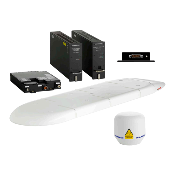
ARINC 781/741 compliant High Gain Antenna (HGA). It delivers secure ACARS services over a robust IP data link together with dual cockpit voice channels. The AVIATOR 700S System is a dual-channel system for cockpit and cabin use and complies with ARINC Characteristic 781 Mark 3 Aviation Satellite Communication Systems. The system provides services in the L-band (1525 to 1559 MHz for the receive channel and 1626.5 to 1660.5 MHz for the transmit channel). - Page 14 • Diplexer/Low Noise Amplifier (DLNA) Type F • ARINC 781/741 compliant with High Gain Antenna (HGA) The CSDU is the master of the AVIATOR 700S System and controls the associated units in the system. The SCM is powered by the CSDU.
- Page 15 General description Compact Satellite Data Unit (CSDU) The AVIATOR 700S Compact Satellite Data Unit (CSDU) is a 2 MCU LRU with an ARINC 600 connector. It is a highly secure system with complete aircraft network segregation for the Aircraft Control Domain (ACD) over the Aircraft Information Service Domain (AISD) and also Passenger Information and Entertainment Services Domain (PIESD).
- Page 16 General description Cockpit interfaces System function Interfaces Cockpit Voice 2x 4-Wire DO-214A, for Cockpit Audio for AMS 1x Discrete input ARINC 781, for Mic-on for/PTT for ACP 1x Discrete input ARINC 781, for Call Place/End for ACP 1x Discrete input ARINC 781, for Cockpit Voice Go Ahead Chime reset for ACP 1x Discrete output, for Call Light for ACP 2x Discrete relay contacts ARINC-781, for Chime signal for ACP...
- Page 17 General description Maintenance interfaces System function Interfaces BITE 1x ARINC 429 output for CFDS 1x ARINC 429 input for CFDS 1x Discrete ARINC 781 output, hardware provisioned for System Fail Data Loading 1x Ethernet for Data Loader A615A 1x Discrete input ARINC 781 for Data Loader Link A 1x ARINC 429 output for Data Loader A615 1x ARINC 429 input for Data Loader A615 Support...
- Page 18 AVIATOR 700S system can be displayed in the MCDU display. Other user interfaces The AVIATOR 700S system has a dedicated AISD Ethernet interface for EFB or other cockpit application requiring IP data communication services. It has also a dedicated PIESD Ethernet interface for voice and data communications for passengers.
-
Page 19: Maintenance Interfaces (Acd)
General description Configuration files for the AVIATOR 700S system The configuration files (Secure ORT and User ORT) for the AVIATOR 700S system are uploaded to the CSDU with an ARINC 615A (Ethernet) or ARINC 615-3 (ARINC 429) compliant data loader. Refer to the ORT Tool User Guide [9]. There are two configuration files: •... -
Page 20: Electrical Interfaces - Overview
3 x Status LED on Front Panel Figure 2-2: Electrical interfaces - overview The interfaces greyed out are disabled or not in use in the AVIATOR 700S Note software. This can be due to interfaces not being supported or reserved for future use. -
Page 21: Part Numbers
Part numbers Part numbers This installation manual is for the AVIATOR 700S system and is applicable to the type and part numbers below: Type number Part number Component name SDU-5045 405045-vvccc Compact Satellite Data Unit (CSDU) SCM-5055 405055-vvccc Compact SDU Configuration Module (SCM), external... - Page 22 Part numbers 2-10 Chapter 2: Introduction 98-158751-C...
-
Page 23: Equipment Drawings
Chapter 3 Equipment drawings This chapter has the following sections. • SDU-5045 Compact Satellite Data Unit • SCM-5055 SDU Configuration Module • HPA-5015 Multi-Carrier High Power Amplifier • DLNA Type F • CSDU/MCHPA tray • CSDU tray connector • MCHPA tray connector The following pages show copies of outline drawings of important system units relevant for the installation. -
Page 24: Sdu-5045 Compact Satellite Data Unit
SDU-5045 Compact Satellite Data Unit SDU-5045 Compact Satellite Data Unit Figure 3-1: Outline Drawing: CSDU (1/2) Chapter 3: Equipment drawings 98-158751-C... - Page 25 SDU-5045 Compact Satellite Data Unit Figure 3-2: Outline Drawing: CSDU (2/2) 98-158751-C Chapter 3: Equipment drawings...
-
Page 26: Scm-5055 Sdu Configuration Module
SCM-5055 SDU Configuration Module SCM-5055 SDU Configuration Module Figure 3-3: Outline drawing SCM-5055 (1/2) Chapter 3: Equipment drawings 98-158751-C... - Page 27 SCM-5055 SDU Configuration Module Figure 3-4: Outline drawing SCM-5055 (2/2) 98-158751-C Chapter 3: Equipment drawings...
-
Page 28: Hpa-5015 Multi-Carrier High Power Amplifier
HPA-5015 Multi-Carrier High Power Amplifier HPA-5015 Multi-Carrier High Power Amplifier Figure 3-5: Outline Drawing: MCHPA (1/2) Chapter 3: Equipment drawings 98-158751-C... - Page 29 HPA-5015 Multi-Carrier High Power Amplifier Figure 3-6: Outline Drawing: MCHPA (2/2) 98-158751-C Chapter 3: Equipment drawings...
- Page 30 DLNA Type F DLNA Type F Figure 3-7: Outline Drawing: DLNA Chapter 3: Equipment drawings 98-158751-C...
-
Page 31: Csdu/Mchpa Tray
CSDU/MCHPA tray CSDU/MCHPA tray Figure 3-8: Outline drawing: CSDU/MCHPA tray 98-158751-C Chapter 3: Equipment drawings... -
Page 32: Csdu Tray Connector
CSDU tray connector CSDU tray connector Figure 3-9: CSDU ARINC 600 tray connector 3-10 Chapter 3: Equipment drawings 98-158751-C... -
Page 33: Mchpa Tray Connector
MCHPA tray connector MCHPA tray connector Figure 3-10: MCHPA ARINC 600 tray connector 98-158751-C Chapter 3: Equipment drawings 3-11... - Page 34 MCHPA tray connector 3-12 Chapter 3: Equipment drawings 98-158751-C...
-
Page 35: Installation
AVIATOR 700S System. Interconnect harness wiring and physical mounting must satisfy all applicable regulations. Also see the accompanying HGA Installation Manual [8] for the antenna and also DLNA Installation Manual, which is part of the AVIATOR 700S system. The information, drawings and wiring diagrams in this manual are intended as a reference for engineering planning only. - Page 36 HGA BITE A429 B, MP08D BP5 +115 VAC Line (Hot) Aircraft ARINC 429 IRS/AHRS A429 A, MP02A BP1 +115 VAC Navigation outputs IRS/AHRS A429 B, MP02B Neutral (Cold) BP3 Chassis Ground Figure 4-1: AVIATOR 700S system (minimum, AC powered) Chapter 4: Installation 98-158751-C...
-
Page 37: Mounting Considerations
Overview For optimum system performance you must follow some guidelines on where to install the components of the AVIATOR 700S system. Installation and placement details are included in this section. For information on requirements to cables refer to the individual sections in Electrical installation and wiring on page 4-6. -
Page 38: Scm-5055 Scm
Mounting considerations 2. Mount according to Amphenol ARINC 600 Document SL-379-3. 3. Mount ground PIN to MP04G on ARINC 600 Connector Chassis Ground: ARINC 600 pin BP3 Amphenol contact part number: AC-781212-304. Fit to wire AWG12 & AWG14 Total max resistance: 25 mOhm. Shield from fluid drippage To fulfill DO-160G Waterproofness Cat. -
Page 39: Hpa-5015 Mchpa
Mounting considerations 4.2.4 HPA-5015 MCHPA Installation Install the MCHPA in one of the locations described below: • Temperature/Non-temperature controlled locations and forced airflow cooling (Tray with fan/plenum) • Temperature/Non-temperature controlled location and supplied airflow cooling (Tray integrated onto a shelf rack system) •... -
Page 40: Electrical Installation And Wiring
Electrical installation and wiring Electrical installation and wiring 4.3.1 Wiring symbols Throughout the wiring section these common symbols are used: Coax Shield Ground (fuselage) Twisted Twisted and shielded Each wiring drawing in this chapter only shows the connections referred to Important in that particular section. -
Page 41: Wiring - Overview
Electrical installation and wiring 4.3.2 Wiring – overview CSDU Ethernet 1 from CSDU to EFB 1 TX+ TP03A (+TX) Ethernet 1 from CSDU to EFB 1 TX- TP04B (-TX) SDU-5045 Ethernet 1 from EFB to CSDU 1 RX+ TP03B (+RX) Ethernet 1 from EFB to CSDU 1 RX- TP04A (-RX) Data from MCDU 1... -
Page 42: To Wire The Csdu With Ac Input
Electrical installation and wiring 4.3.3 To wire the CSDU with AC input ARINC-781 compliant. The aircraft power bus provides the electric power required to operate the CSDU, and a chassis connection to the aircraft chassis and the installation tray. The +115 VAC power wire must include a circuit breaker capable of carrying the required current continuously under the required environmental conditions. - Page 43 Electrical installation and wiring Description of the CSDU power supply +115 VAC Power (BP1, BP5) The target line impedance should be as low as possible; 1 Ohm preferred maximum; should not exceed 4 Ohms. Required current capability for the Circuit Breaker: 99 W @ 90 VAC which equals 1.1 A at the required environmental conditions.
-
Page 44: To Wire The Mchpa With Ac Input
Electrical installation and wiring 4.3.4 To wire the MCHPA with AC input ARINC-781 compliant. The aircraft power bus provides the electric power required to operate the MCHPA, and a chassis connection to the aircraft chassis and the installation tray. The +115 VAC power wire must include a circuit breaker capable of carrying the required current continuously under the required environmental conditions. - Page 45 Electrical installation and wiring Description of the MCHPA power supply +115 VAC Power (BP1, BP7) The target line impedance should be as low as possible; 1 Ohm preferred maximum; should not exceed 4 Ohms. Required current capability for the Circuit Breaker: 300 W @ 90 VAC which equals 3.33 A at the required environmental conditions.
-
Page 46: To Wire The Scm
Electrical installation and wiring 4.3.5 To wire the SCM Wiring diagram The following drawing shows the wiring of the SCM to the CSDU. The SCM connector pin-out is compliant with ARINC-781. 10 meter Interconnecting Cable: Carlisle (Tensolite) P/N NF24Q100-01 100Base-T Ethernet Cable. 100ohm ±10%, 13pF/ft, AVG24 DB15 FEMALE (Rear view) -
Page 47: To Wire The Mcdu 1, 2 And 3
4.3 for the maximum loss requirement at 1.6 GHz. Wiring diagram See Figure 4-1: AVIATOR 700S system (minimum, AC powered) for the wiring for an AVIATOR 700S System with the HPA-5015 MCHPA For the requirements to RF cable see Recommended RF cables on page 4-38 on pin TP71. -
Page 48: To Wire The Cmu 1 And 2
Electrical installation and wiring 4.3.8 To wire the CMU 1 and 2 ARINC-781 compliant. Description The Communications Management Unit (CMU) or equivalent is responsible for integrating data communications or datalinks on the aircraft. The CMU manages communication across multiple subnetworks, including VHF and SATCOM networks. Wiring diagram See Wiring –... -
Page 49: To Wire Irs/Gnss
Electrical installation and wiring Description of the cockpit audio 1 and 2 There are two 4-wire interfaces to be connected to a headset. Wiring diagram See Wiring – overview on page 4-7 Pins for cockpit audio 1 and 2 CSDU pin Description MP04A Cockpit audio input 1. -
Page 50: To Wire Eicas/Fws
Electrical installation and wiring Wiring diagram See Wiring – overview on page 4-7 Pins for antenna BITE CSDU pin Description MP08C Data from antenna BITE. A. (A429 input) MP08D Data from antenna BITE. B. (A429 input) 4.3.13 To wire EICAS/FWS ARINC-781 compliant. -
Page 51: To Wire Airborne Data Loader
Electrical installation and wiring CSDU Pin Description MP03C Cockpit Voice Call Light output 1. Cockpit Voice discrete output MP03E ACARS Service Available discrete output (spare) MP03H Cockpit Voice Call Light output 2. Cockpit Voice discrete output MP04C Cockpit Voice Mic On input 1. Cockpit Voice discrete input MP04E Spare MP04H... -
Page 52: To Wire Antenna Multi Control
Electrical installation and wiring CSDU pin Description MP09K To airborne data loader B 4.3.16 To wire Antenna multi control ARINC-781 compliant. Description of the antenna multi control Arinc 429 output to control High Gain Antenna. Wiring diagram See Wiring – overview on page 4-7 Pins for antenna multi control CSDU pin Description... -
Page 53: To Wire Ethernet 11 (Aisd#2 Or Efb2)
Electrical installation and wiring • Ethernet Port Definition: Electronic Flight Bag 1 • Security Domain: Airline Information Services Domain (AISD) Ethernet 11 (AISD#2): Description of Ethernet 1 (AISD#1 or EFB 1) The EFB 1 interface is for cockpit (AISD) applications which require an IP data connection, for example for EFB connectivity. -
Page 54: To Wire Ethernet 3 (Adl In Acd)
Electrical installation and wiring 4.3.20 To wire Ethernet 3 (ADL in ACD) ARINC-781 compliant. Description • Ethernet Port Definition: Airborne Data Loader • Security Domain: Aircraft Control Domain (ACD) Wiring diagram See Wiring – overview on page 4-7 Pins for Ethernet 3 (ACD) Quadrax connector CSDU pin Description MP 1T 1 Ethernet 3 from CSDU to ADL + MP 1T 2 Ethernet 3 from ADL to CSDU +... -
Page 55: To Wire Ethernet 4 (Acd#1)
Electrical installation and wiring • Security Domain: Passenger Information Entertainment Services Domain (PIESD) Description of Ethernet 12 (PIESD#2) This interface is for cabin (PIESD) applications. Future use of the Cabin 2 interface is Crosstalk master/slave interface to other CSDU. Wiring diagram See Wiring –... -
Page 56: To Wire The Maintenance Interfaces
Electrical installation and wiring Description This interface is test purposes only and is only accessible when the aircraft is in Flight Test mode. Wiring diagram See Wiring – overview on page 4-7 Pins for Ethernet 5 (ACD#2) CSDU pin Description MP06E Ethernet 5 (Spare) from CSDU to User + (ACD#2) - Page 57 Electrical installation and wiring The following list shows the pins used for the Micro USB interface (Front connector on the CSDU). Pin Name Description +5 VDC Data - Data + Not Used Signal ground Description of the maintenance interfaces on the CSDU Use the maintenance interface on the front of the CSDU or the AISD 1/EFB 1 (Ethernet 11) interface for maintenance purposes.
- Page 58 Electrical installation and wiring The front panel status LEDs (see Status signalling with LEDs on page 7-8) will display the following: • Steady red: A fault, which may degrade the system operation, is present in the CSDU. • Flashing short green/long pause: Power On Self-Test (POST) or Person Activated Self-Test (PAST) is in progress.
-
Page 59: Csdu Arinc 600 Connector Block
Electrical installation and wiring 4.3.26 CSDU ARINC 600 connector block ARINC 600 connector drawing - overview Size 2 Shell receptacle Top Plug (TP): Insert arrangement 08 Pin 71 Receptacles A B C D E F G H J K 1 Size 1 Coax cavity 50 Size 22 sockets •... - Page 60 Electrical installation and wiring ARINC 600 connector drawings with functions The following drawing shows the top plug, middle plug and bottom plug of the SDU rear receptacle with pin functions. For wiring details of this connector see Electrical installation and wiring on page 4-6. The pins in grey colour are not used or empty cavity and not connected inside Note CSDU.
- Page 61 Electrical installation and wiring Call Resv Ext Call Data from Data from Multi-Control Multi-Control Data from Data from Place/End SCM P wr Reset Place/End MCDU 1 MCDU 1 Output Output MCDU 2 MCDU 2 Discrete +8 to 15V Discrete Discrete Input 1 Input Input 2...
- Page 62 Electrical installation and wiring 115V COLD No Connect No Connect No Connect No Connect Chassis GROUND No Connect 115v Ant. DLNA Control Figure 4-12: CSDU Bottom Plug in rear receptacle with pin functions 4-28 Chapter 4: Installation 98-158751-C...
- Page 63 Electrical installation and wiring Pin-out for CSDU rear receptacle (top plug) Pin name Pin name TP04F No Connect TP71 RF TX or RX/TX, to HPA TP04G No Connect TP01A ATE pin 1 TP04H Empty Cavity TP01B ATE pin 2 TP04J Ethernet 11 from EFB2 to CSDU- (AISD#2) TP01C ATE pin 3...
- Page 64 Electrical installation and wiring Pin-out for CSDU rear receptacle (middle plug) Pin name and description Pin name and description MP04B Cockpit audio input 1 Low MP01A Data from MCDU 1 A MP04C Cockpit Voice Mic On Input 1 MP01B Data from MCDU 1 B MP04D SDU Data to SCM B MP01C...
- Page 65 Electrical installation and wiring Pin name and description Pin name and description MP10D Data from BSU HPA Mute B MP07A AES ID input A MP10E LGA LNA On/Off Control discrete output MP07B AES ID input B MP10F BITE Input from LGA LNA MP07C Spare discrete input #4 MP10G...
- Page 66 Electrical installation and wiring Pin-out for CSDU rear receptacle (bottom plug) Pin name and description 115 V COLD. 115 VAC power return 28 V HOT. 28 VDC power (No Connect - Provision only) Chassis Ground 28 V GND. 28 VDC power return (No Connect - Provision only) 115V HOT.
-
Page 67: Mchpa Arinc 600 Connector Block
Electrical installation and wiring 4.3.27 MCHPA ARINC 600 connector block ARINC 600 connector drawing - overview Figure 4-13: MCHPA ARINC 600 connector specifications Other pins are not used by MCHPA. Note 98-158751-C Chapter 4: Installation 4-33... - Page 68 Electrical installation and wiring Pin-out for MCHPA rear receptacle (top plug) Pin name Pin name TP04F No Connect TP71 RF IN from CSDU TP04G No Connect TP01A No connect TP04H No connect TP01B No connect TP04J No connect TP01C No connect TP04K No connect TP01D...
- Page 69 Electrical installation and wiring Pin-out for MCHPA rear receptacle (middle plug) Pin name Pin name MP04F No Connect MP71 RF OUT to DLNA MP04G No Connect MPMP01A No connect MP04H No connect MP01B No connect MP04J No connect MP01C No connect MP04K No connect MP01D...
- Page 70 Electrical installation and wiring Pin-out for MCHPA rear receptacle (bottom plug) Pin name and description 115 V HOT. 115 VAC power 115 V COLD. 115 VAC power return Chassis Ground No Connect BP10 BP11 BP12 BP13 4-36 Chapter 4: Installation 98-158751-C...
-
Page 71: Recommended Cables
Recommended cables Recommended cables 4.4.1 Introduction This section lists recommended cables and allowed cable lengths for the cables in the AVIATOR 700S system. For specific cable requirements see the applicable section in 4.3 Electrical Important installation and wiring. 4.4.2 Allowed cable lengths for power cables... -
Page 72: Recommended Power Cables
Manufacturer: Carlisle (Thermax) MIL-DTL-22759/86-18 Manufacturer: Carlisle (Thermax) MIL-DTL-22759/86-12 4.4.4 Recommended RF cables Recommended cables for AVIATOR 700S must be compliant with ARINC Characteristic 781-7 [3]. 4.4.5 Recommended cables for ARINC 429 The cables for the ARINC 429 interfaces must be twisted and shielded. They must conform to the standards for aeronautical use. -
Page 73: Recommended Cable Between The Scm And The Csdu
Verifying the installation You must perform certain check procedures during and after installation of the AVIATOR 700S system. The first check procedures are performed after wiring, but before inserting LRUs.For information on the required and recommended check procedures, refer to Verification on page 6-1. - Page 74 Activation of airtime services SwiftBroadband USIM cards The AVIATOR 700S system is delivered with four USIM cards permanently installed in the SCM. The USIM cards are pre-authenticated by Inmarsat and identified by their unique IMSI (International Mobile Subscriber Identity) number. The length of the IMSI is 15 digits.
-
Page 75: Setup Of The System
Chapter 5 Setup of the system This chapter has the following sections: • Software upload • SATCOM system ready for use Line of sight Note You can configure the system while the aircraft is in the hangar. Note that you cannot typically check the satellite communication while the aircraft is still in the hangar. -
Page 76: Uploading Software
2. Upload the files using a compliant data loader, see the data loader’s instruction manual. SATCOM system ready for use Having installed the AVIATOR 700S system and loaded the necessary software, verify that the system is fully operational. Line of sight during operation! -
Page 77: Verification
4. Interference Test. After the functional test, make an interference test. This test is to verify that transmission from the AVIATOR 700S system has no effect on the avionics of the aircraft, particularly navigation equipment. Refer to Interference Test on page 6-4. -
Page 78: Pre-Installation Check
Pre-Installation Check Pre-Installation Check It is recommended to check the installation before inserting LRUs. The following list provides some of the most important issues, but other additional checks may be relevant for the specific installation. Reference Value/ Item Description of Check ... -
Page 79: Functional Test, On Ground
Check that the Fail/Pass LED is green Check that the Logon LED is green MCDU Make an aircraft to ground call AVIATOR 700S headsets #1 to User Manual [7] Make a ground to aircraft call AVIATOR 700S User Manual [7]... -
Page 80: Interference Test
It is recommended to do an interference test to ensure that transmission from the AVIATOR 700S system does not influence any of the primary avionics on the aircraft. This test is not a replacement for any EMC tests in connection with e.g. an... -
Page 81: Functional Test, Airborne
Item Description of Check Reference Comment MCDU Make an air to ground call and AVIATOR 700S headsets #1 keep it up during a 360 turn. User Manual [7] to #2 Make a ground to air call AVIATOR 700S User Manual [7]... - Page 82 Functional test, airborne Chapter 6: Verification 98-158751-C...
-
Page 83: Maintenance And Troubleshooting
Maintenance requirements and instructions for continued airworthiness of the Cobham Aerospace Communications units in the AVIATOR 700S System are defined here. The AVIATOR 700S System (CSDU, SCM and MCHPA) requires no periodic scheduled servicing tasks. When replacing the CSDU, it is important to leave the SCM installed in the Note aircraft, because the SCM contains the aircraft-specific configuration data. -
Page 84: Maintenance Instructions
7.1.2 Maintenance instructions Documentation Maintenance information for the AVIATOR 700S System is contained in this manual. Place the wiring diagram information in this manual in the aircraft operator's appropriate aircraft wiring diagram manuals. Inoperative units If a system component is inoperative, remove or replace the unit. - Page 85 Continued Airworthiness Not required MCHPA Not required Table 7-1: Periodic scheduled maintenance tasks The recommended periodic scheduled inspection tasks to be added to the aircraft operator's appropriate aircraft maintenance program are as follows: CSDU Not required Not required MCHPA Not required Table 7-2: Periodic scheduled inspection tasks The recommended periodic scheduled preventative maintenance tasks to be added to the aircraft operator's appropriate aircraft maintenance program are as follows:...
-
Page 86: Helpdesk
Helpdesk Helpdesk If this manual does not provide the remedies to solve your problem, you may want to contact your Airtime Provider or your local distributor. 7.2.1 System support If you need assistance with problems caused by the CSDU, SCM or MCHPA, call a distributor in your area. -
Page 87: Software Update
Software update Software update See Software upload in chapter 5. To exchange an LRU This document describes the procedures for removal and re-installation of the AVIATOR 700S LRUs: • CSDU (405045-vvccc). • SCM (405055-vvccc). • MCHPA (405015-vvccc). 7.4.1 Time required The time required for removal and re-installation of an LRU is estimated to 15 minutes. -
Page 88: Removal And Re-Installation Of The Scm (Scm-5055)
To exchange an LRU 7.4.4 Removal and re-installation of the SCM (SCM-5055) Removal 1. Ensure that power is removed from the SATCOM system before removing the SCM. 2. Release the screw-locks on the D-sub connector and remove the 15 pin D-sub connector from the SCM. -
Page 89: Troubleshooting
CSDU. Also, during operation a Continuous Monitoring BITE function is performed. Each LRU in the AVIATOR 700S system has its own BITE function but they are all controlled and monitored by the CSDU in the system. -
Page 90: Status Signalling With Leds
Troubleshooting 7.5.2 Status signalling with LEDs LEDs on CSDU During the power-up procedure all LEDs on the front plate are orange. If all 3 LEDs on the front stay orange after power up, check the AC supply of the CSDU. If the wiring is good, the CSDU software may be corrupted. -
Page 91: Initial Troubleshooting
Troubleshooting 7.5.3 Initial troubleshooting Overview This section describes an initial check of the primary functions of the AVIATOR 700S System, and provides some guidelines for troubleshooting, if one of the checks should fail. Means available for troubleshooting The following means are available for troubleshooting: •... -
Page 92: Returning Units For Repair
Should you need to send the product for repair, please read the below information before packing the product. The shipping carton has been carefully designed to protect the AVIATOR 700S and its accessories during shipment. This carton and its associated packing material should be used when repacking for shipment. - Page 93 Disposal of electrical and electronic equipment Disposal of electrical and electronic equipment Old electrical and electronic equipment marked with this symbol can contain substances hazardous to human beings and the environment. Never dispose these items together with unsorted municipal waste (household waste). In order to protect the environment and ensure the correct recycling of old equipment as well as the re-utilization of individual components, use either public collection or private collection by the local distributor of old electrical and...
- Page 94 Disposal of electrical and electronic equipment 7-12 Chapter 7: Maintenance and troubleshooting 98-158751-C...
- Page 95 Appendix A Equipment specifications Introduction This appendix has the following sections: • SDU-5045 Compact Satellite Data Unit • SCM-5055 Configuration Module • HPA-5015 Multi-Carrier High Power Amplifier Important note! The information, drawings, and wiring diagrams contained in this manual are intended as a reference for engineering planning only.
- Page 96 Transparency time 200 ms Typical Power Consumption: AC: 44 W CSDU alone in a Class 6 system Power provided for SCM: 4.5 W (AVIATOR 700S) Maximum heat dissipation <50 W Connectors Rear: ARINC 600 Attachment 11 Front: micro USB (for maintenance).
- Page 97 SDU-5045 Compact Satellite Data Unit Characteristics Specification Maximum resistance, AC input < 1.0 Ohm Altitude For installation in non-pressurized locations: Max. 55000 ft (Cat-F2) Decompression For installation in pressurized locations: 55000 ft (Cat. A2) Overpressure For installation in pressurized locations: -15000 ft (Cat.
- Page 98 SCM-5055 Configuration Module SCM-5055 Configuration Module Characteristics Specification Dimensions (L x W x H) 114.30 mm x 101.60 mm x 25.78 mm (4.50" x 4.00" x 1.015") Weight 200 ± 30 g • Controlled and Non-controlled temperature Mounting locations with convection airflow cooling •...
- Page 99 HPA-5015 Multi-Carrier High Power Amplifier HPA-5015 Multi-Carrier High Power Amplifier Characteristics Specification Dimensions 2 MCU ARINC 600 enclosure 323.00 mm x 61.00 mm x 199.70 mm (12.72" x 2.40" (L x W x H) x 7.86") Weight The maximum weight of the MCHPA is 5.0 kg (11 lbs) Mounting Mount in an ARINC 600 2 MCU tray.
- Page 100 HPA-5015 Multi-Carrier High Power Amplifier Characteristics Specification Relative humidity 95% non-condensing at +50°C Environmental categories See appendix C, DO-160G specifications, Multi- Carrier High Power Amplifier (MCHPA) on page C- Table A-3: MCHPA specifications Chapter A: Equipment specifications 98-158751-C...
-
Page 101: Appendix B System Messages
System messages This appendix has the following sections: • BITE error codes The AVIATOR 700S system shows system messages in connected display units (e.g. MCDU) or in the security and system log files of the CSDU when extracted in maintenance-allowed mode. - Page 102 BITE error codes Fault Fault message FDCE Failure cause Consequences on the system message subject type 1 code MCDU1 SATCOM system receives an MCDU1 is unusable for Loss of (2CA1) ARINC 429 message from MCDU1 control/status of the SATCOM with a SSM set to NCD/FW/FT system.
- Page 103 BITE error codes Fault Fault message FDCE Failure cause Consequences on the system message subject type 1 code MCDU2(2CA SATCOM system receives an MCDU2 is unusable for Loss of 2)/SDU1(5RV ARINC 429 message from MCDU2 control/status of the SATCOM 1)/WRG with a SSM set to Silent system ATSU2(1TX2...
- Page 104 BITE error codes Fault Fault message FDCE Failure cause Consequences on the system message subject type 1 code SCM1 The SCM is overheated Probable loss of communications SATCO (78RV1)/ M Fault OVER TEMPERA HPA-HI The HPA is overheated Probable loss of communications SATCO GAIN(7RV1)/ M Fault...
- Page 105 BITE error codes Fault Fault message FDCE Failure cause Consequences on the system message subject type 1 code SDU1(5RV1)/ Discrete Output failure No light indication of incomming No light call on channel 2 or No light indication indication of incomming call on channel 1 incoming call on...
-
Page 106: Bite Error Codes
BITE error codes Chapter B: System messages 98-158751-B... -
Page 107: General Do-160 Information
C.1.1 Certifying agency Approval of the installation of the AVIATOR 700S system is not authorized by this installation manual. Acceptance for the installation and use of the AVIATOR 700S system and its associated components must be obtained through the appropriate offices of the FAA or other certifying agency. - Page 108 Compact Satellite Data Unit (CSDU) Compact Satellite Data Unit (CSDU) Part Number: SDU-5045 DO160 G section Category and Environmental variable requirements (Unless otherwise specified) Temperature and Altitude [(A2F2)Z] Ground Survival Low Temperature Test - 4.5.1 55°C Short-Time Operating Low Temperature 4.5.1 Test -40°C Operating Low Temperature Test -40°C...
- Page 109 Compact Satellite Data Unit (CSDU) DO160 G section Category and Environmental variable requirements (Unless otherwise specified) High-Level, Short Duration Vibration H(R) Explosion Atmosphere Waterproofness Fluids Susceptibility Sand & Dust Fungus Resistance Salt Fog Magnetic Effect Power Input A(WF)HLPI Voltage Spike Audio Frequency Conducted Susceptibility AC Power...
- Page 110 Compact Satellite Data Unit (CSDU) DO160 G section Category and Environmental variable requirements (Unless otherwise specified) Lightning Direct Effects Icing Electrostatic Discharge Fire, Flammability Federal Aviation Regulation FAR 25.853(a) & Appendix F, part I, §(a)(1)(ii) FAR 25.853(a) & Appendix F, part I, §(a)(1)(v) FAR 25.869 (a)(1) &...
- Page 111 Configuration Module (SCM) Configuration Module (SCM) Part Number: SCM-5055 DO160 G section Category and Environmental variable requirements (Unless otherwise specified) Temperature and Altitude Ground Survival Low Temperature Test - 4.5.1 55°C Short-Time Operating Low Temperature 4.5.1 Test -40°C Operating Low Temperature Test -40°C 4.5.2 Ground Survival High Temperature Test 4.5.3...
- Page 112 Configuration Module (SCM) DO160 G section Category and Environmental variable requirements (Unless otherwise specified) Bench Handling Shocks MIL-STD 810G, Method 516.6, Proc. VI Vibration Standard Random Vibration S(B3) High-Level, Short Duration Vibration H(R) Explosion Atmosphere Waterproofness Fluids Susceptibility Sand & Dust Fungus Resistance Salt Fog Magnetic Effect...
- Page 113 Configuration Module (SCM) DO160 G section Category and Environmental variable requirements (Unless otherwise specified) Electrostatic Discharge (DO-160) Fire, Flammability (DO-160) Federal Aviation Regulation FAR 25.853(a) & Appendix F, part I, §(a)(1){ii) FAR 25.853(a) & Appendix F, part I, §(a)(1)(v) FAR 25.869 (a)(1) & Appendix F part I Table C-2: Common environmental conditions and tests (DO160G) for SCM (Continued) a.
- Page 114 Multi-Carrier High Power Amplifier (MCHPA) Multi-Carrier High Power Amplifier (MCHPA) Part Number: HPA-5015 DO160 G section Category and Environmental variable requirements (Unless otherwise specified) Temperature and Altitude [(A2F2)Z] Ground Survival Low Temperature Test - 4.5.1 55°C Short-Time Operating Low Temperature 4.5.1 Test -40°C Operating Low Temperature Test -40°C...
- Page 115 Multi-Carrier High Power Amplifier (MCHPA) DO160 G section Category and Environmental variable requirements (Unless otherwise specified) High-Level, Short Duration Vibration H(R) Explosion Atmosphere Waterproofness Fluids Susceptibility Sand & Dust Fungus Resistance Salt Fog Magnetic Effect Power Input A(WF)HLPI Voltage Spike Audio Frequency Conducted Susceptibility AC Power...
- Page 116 Multi-Carrier High Power Amplifier (MCHPA) DO160 G section Category and Environmental variable requirements (Unless otherwise specified) Lightning Direct Effects Icing Electrostatic Discharge Fire, Flammability Federal Aviation Regulation FAR 25.853(a) & Appendix F, part I, §(a)(1)(ii) FAR 25.853(a) & Appendix F, part I, §(a)(1)(v) FAR 25.869 (a)(1) &...
-
Page 117: Appendix D References
ARINC 429P1-19 Digital Information Transfer System (DITS), Part 1, Functional Description, Electrical Interfaces, Label Assignments and Word Formats, January 22, 2019 Other references AVIATOR 700S User Manual* HGA-7001 Installation Manual (862-A0089_IM) ORT Tool User Guide* [10] AVIATOR Operational User Guidance (99-157303) -
Page 118: Other References
Other references Chapter D: References 98-158751-C... -
Page 119: Glossary
Glossary Glossary Aeronautical Administrative Communications ACARS Aircraft Communications Addressing And Reporting System ACAS Aircraft Collision Avoidance System.. Aircraft Control Domain Audio Control Panel Avionics Communication Router Automatic Direction Finder. A navigation receiver based on the AM radio band. A very simple device which literally points towards the station that is tuned in. - Page 120 Glossary HELGA HLD Enhanced Low Gain Antenna High Power Amplifier, Low Noise Amplifier and Diplexer ICAO International Civil Aviation Organization Instrument Landing System. A system of tightly focused transmitters located at the end of a runway that provides flight guidance information to flight crews. IMSI International Mobile Subscriber Identity IPSEC...
- Page 121 Very High Frequency. 30-300 MHz. VHF Omnidirectional Range Virtual Private Network Weight on Wheels Williamsbrug SDU Controllers 98-158751-C Chapter Glossary: Glossary-3...
- Page 122 Glossary-4 Chapter Glossary: 98-158751-C...
-
Page 123: Index
Index Index part number 2-9 about this manual 1-1 SDU rear receptacle 4-25 activation contact SIM card 4-40 address -ii address contact information 7-4 manufacturer -ii Continued Airworthiness 6-1, 7-1 airtime services 4-39 Airworthiness, Continued 6-1, 7-1 defect units 7-2 antenna discrete signals systems 2-6... - Page 124 Logon LED on SDU 7-8 Maintenance connector PC and Reset, wiring 4-22 manufacturer address -ii messages B-1 minimum system drawing 4-2 mounting considerations 4-3 HLD 4-5 SDU 4-3, 4-4, 4-5 operation 2-7 outline drawings 3-1 part numbers connector 2-9 installation kit 2-9 PAST 7-7 PC, Maintenance wiring 4-22...
- Page 125 power source, power return 4-39 recommended 4-39 DO-160 form C-2 Environmental Qualification Form C-2 location in aircraft 4-4 mounting 4-3, 4-4, 4-5 power cables 4-9, 4-11 rear receptacle 4-25 Tray connector, outline drawing 3-10, 3-11 SIM card activation 4-40 software update 7-5 specifications A-1 circuit breaker 2-9 standards, applicable D-1...
- Page 126 Index-4 Chapter Index: 98-158751-C...
- Page 128 98-158751-C www.cobhamaerospacecommunications.com Cobham Public...
Need help?
Do you have a question about the AVIATOR 700S and is the answer not in the manual?
Questions and answers