Associated Research HypotULTRA 7800 Operation And Service Manual
Hypotultra series, electrical safety compliance analyzer ac/dc hipot, insulation resistance, continuity and ground bond test instruments usb/rs-232 interface standard on all models
Hide thumbs
Also See for HypotULTRA 7800:
- Operation and service manual (206 pages) ,
- Quick start manual (5 pages)
Table of Contents
Advertisement
Operation and Service Manual
HypotULTRA
Series
®
Models 7800, 7804, 7820, 7850 and 7854
Electrical Safety Compliance Analyzer
AC/DC Hipot, Insulation Resistance, Continuity and Ground Bond Test Instruments
USB/RS-232 Interface standard on all models
Serial
— — — — — — — —
Item 39658
Version 2.03
•
Printed June 20th, 2018
RoHS 2
*
COMPLIANT
2011/65/EU
*Select models only.
See specs for details.
13860 West Laurel Drive, Lake Forest, Illinois, 60045 USA
1
© Associated Research 2017
Advertisement
Table of Contents

Related Manuals for Associated Research HypotULTRA 7800


Summary of Contents for Associated Research HypotULTRA 7800
- Page 1 — — — — — — — — Item 39658 Version 2.03 • Printed June 20th, 2018 RoHS 2 COMPLIANT 2011/65/EU *Select models only. See specs for details. 13860 West Laurel Drive, Lake Forest, Illinois, 60045 USA © Associated Research 2017...
- Page 2 (Cd), Hexavalent chromium (Cr (VI)), Polybrominated biphenyls (PBB), Polybrominated diphenyl ethers (PBDE), Deca-BDE included. Last two digits of the year in which the CE marking was affixed: 14 The technical file and other documentation are on file with Associated Research Joseph Guerriero President...
- Page 3 (Cd), Hexavalent chromium (Cr (VI)), Polybrominated biphenyls (PBB), Polybrominated diphenyl ethers (PBDE), Deca-BDE included. Last two digits of the year in which the CE marking was affixed: 14 The technical file and other documentation are on file with Associated Research Joseph Guerriero President...
- Page 4 5-Year Program All Associated Research instruments include the opportunity to extend the standard warranty for up to a period of 5 years. Returning instruments to Associated Research for their annual calibration and inspection will extend the instrument’s warranty for an additional year. This warranty is extendable for up to five years and annual returns must be made in succession starting one year after the original purchase date.
-
Page 5: Table Of Contents
NOTE: This is an interactive PDF, if viewing on a computer click on our quick links to jump quickly to that section. Return to the Table of Contents by simply clicking on the page number with a above it in the bottom right corner. © Associated Research 2017... -
Page 6: Safety Precautions And Warning Symbols For High Voltage Testing
Le HypotULTRA, des tensions et des courants qui peuvent causer des chocs électriques dangereux ou mortel. Pour éviter toute blessure ou un décès accidentels, ces procédures de sécurité doivent être strictement respectées lors de la manipulation et l’utilisation de l’appareil de contrôle. © Associated Research 2017... -
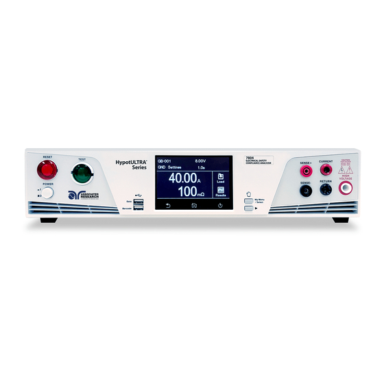
Page 7: Front Panel Controls (7800, 7820 And 7850)
HIGH VOLTAGE OUTPUT TERMINAL - Connector used to attach the high voltage test lead, adapter box high voltage lead or test fixture high voltage lead to the instrument. This connection provides the high voltage used during a Hipot test. © Associated Research 2017... -
Page 8: Rear Panel Controls (7800, 7820 And 7850)
INPUT POWER RECEPTACLE - Standard IEC 320 connector for connection to a standard NEMA style line power (mains) cord. FUSE RECEPTACLE - To change the fuse, unplug the power (mains) cord and turn the fuse receptacle counter-clockwise. This will expose the fuse compartment. Please replace the fuse with one of the proper rating. © Associated Research 2017... -
Page 9: Front Panel Controls (7804 And 7854)
DATA USB PORT - This USB style port allows for connecting a USB flash drive to extract test and system data. TOGGLE - This button allows you to toggle between test files if you are wearing high voltage gloves. Continued on next page © Associated Research 2017... - Page 10 This connection provides the high voltage used during a Hipot test. HIGH VOLTAGE INDICATOR - This indicator flashes to warn the operator that high voltage is present at the high voltage output terminal. © Associated Research 2017...
-
Page 11: Rear Panel Controls (7804 And 7854)
REMOTE SIGNAL OUTPUT - 9-Pin D-type subminiature female connector for monitoring PASS, FAIL, and PROCESSING output relay signals. REMOTE SIGNAL INPUT - 9-Pin D-type subminiature male connector for remote control of TEST, RESET, and REMOTE INTERLOCK DISABLE functions, as well as MEMORY SELECTION. Continued on next page © Associated Research 2017... - Page 12 (mains) cord. FUSE RECEPTACLE - To change the fuse, unplug the power (mains) cord and turn the fuse receptacle counter-clockwise. This will expose the fuse compartment. Please replace the fuse with one of the proper rating. © Associated Research 2017...
-
Page 13: Setup Instructions
The instrument screen will then default to the main menu. The default screen is the main menu screen of the instrument. From this screen you can access all the functions and settings of the instrument: Main Menu © Associated Research 2017... -
Page 14: Getting To Know Your Instrument
The HypotULTRA touch screen has 3 functional keys: Back, Home and Perform Tests: Use the Back key to return to a previous menu. Use the Home key to return to the Main Menu. Use the Perform Tests key to navigate to the Perform Tests screen. © Associated Research 2017... - Page 15 You can drag and drop test files and steps on certain HypotULTRA screens. To use this feature simply touch and hold the test file, test step or parameter. Drag the file to the appropriate location as shown in the following screen to the right. © Associated Research 2017...
-
Page 16: Main Menu
Security Menu - Access instrument FailCHEK Menu - Check the instrument’s lockout and security features. failure detectors *Note – Details of each system and test parameter are listed in the relevant sections of the manual. © Associated Research 2017... -
Page 17: Setup System
From the default main menu touch the Setup System icon to enter the Setup System sub menu. This is where all System Parameters can be edited: Main Menu Setup System Menu Setup System Menu Cont. Time and Date Menu Calibration Alert Menu Continued on next page © Associated Research 2017... - Page 18 Setup System Continued Hardware Menu Results Menu Information Screen Import Menu Export Menu © Associated Research 2017...
- Page 19 Setup System Menu Time and Date Menu Enter the current date to set System Enter current time to set System Time. Date. Select the Date Format for System Date. Select the Time Format for System Time. © Associated Research 2017...
- Page 20 Enter a Calibration Alert Date. The above Calibration Alert screen will be displayed upon powering up the instrument, on and after the Calibration Alert Date. This screen will display the Calibration Due Date of the instrument. © Associated Research 2017...
- Page 21 Information Screen The Information screen displays all instrument information including: Model Number, Serial Number, Calibration Date, Company Information and Firmware Version. © Associated Research 2017...
- Page 22 The User Interface menu allows the user to edit Results, Touch Sound, Alarm Volume, Language, Home Screen, Color Style and Dual Test parameters. Setup System Menu User Interface Menu User Interface Cont. Select end of test Screen. Select ON or OFF. Result Touch Sound Continued on next page © Associated Research 2017...
- Page 23 User Interface Continued Enter Alarm Volume level. Select System Language. Select start up Home Screen. Select System Color Style. Select Dual Test ON or OFF for Dual Remote Palm Switches. © Associated Research 2017...
- Page 24 When the Dual Test parameter is turned OFF, the Test and Reset switches on the front and rear panel behave the same as the standard instrument, and are controlled by the PLC Remote On/Off selection. © Associated Research 2017...
- Page 25 Hardware menu if a USB flash drive is inserted into the Data port on the front panel of the instrument. Setup System Menu Import Menu Import System file. Import a single Test file. Import System and all Test files. Import all Test files. © Associated Research 2017...
- Page 26 Setup System Cont. Menu Export Menu Enter file name for exporting System Select the Test File to export. File. Enter file name for exporting System Enter file name for exporting All Files. and All Files. © Associated Research 2017...
- Page 27 Select PLC Remote ON or OFF. This screen comes up when pressing TEST button while PLC is ON warning customer to adjust PLC setting if need to use the TEST button. Continued on next page © Associated Research 2017...
- Page 28 Hardware Continued Select ON or OFF. Select ON or OFF. Single Step Fail Stop Select Measurement. Select ProVOLT ON or OFF (optional). Barcode Menu. Results Setup Menu. © Associated Research 2017...
- Page 29 ACW test is followed by a DCW test, the ProVOLT function will not operate 2. If stepping up the voltage between steps, the ramp down parameter is ignored. 3. If stepping down the voltage between steps, the ramp up parameter is ignored. © Associated Research 2017...
- Page 30 Last Cal Alert Security Initializing the instrument will overwrite all memories and steps with ACW default parameters! WARNING Initialisation de l’instrument va écraser toutes les mémoires et les étapes avec les paramètres par défaut ACW © Associated Research 2017...
- Page 31 If there is a problem with the connection to the barcode reader or an incompatible device is plugged into the USB barcode port, the following message will appear: If the USB barcode device is removed while the instrument is powered on, the following message will appear: © Associated Research 2017...
- Page 32 Note that there is a “0” in the Product Number field because the Barcode I/P setting is SERIAL#. When the Barcode I/P setting is RUN FILE or OFF, these fields are not included in the TD? and RD x? responses. © Associated Research 2017...
- Page 33 Barcode I/P Barcode Menu Select Barcode input option. Select Barcode type. Example SERIAL # screen. Example PRODUCT # screen. Example SER/PROD screen. © Associated Research 2017...
- Page 34 Barcode Autostart Barcode Menu Select Autostart ON or OFF. © Associated Research 2017...
- Page 35 Select Int. memory if you wish to store the test results on the onboard instrument memory. Select USB disk if you wish to save the test results on an external USB flash drive. For best results use the USB flash drive provided by Associated Research.
- Page 36 Internal Memory Result Setup USB DISK Menu. Select Location for Result Data. Enter File Name. Select type of Test Results to be saved. © Associated Research 2017...
-
Page 37: Setup Tests
Scroll through each parameter Press the Test Screen button to Press ENTER to save your file to adjust values based on your exit out of Parameters. changes. You will be redirected application. to the Test Screen. © Associated Research 2017... -
Page 38: Setup Continuity Test
Enter for resistance. Enter for resistance. Max Limit Min Limit Enter test Dwell Time. Enter value to manually set Select settings. Offset Scanner Offset or Press TEST to perform auto offset. Enter text for Prompt. © Associated Research 2017... -
Page 39: Setup Ground Bond Test
Enter test value. Enter test value. Current Voltage Enter HI-Limit for resistance. Enter for resistance. Enter for Voltage. LO-Limit HI-Limit Enter for Voltage. LO-Limit Enter test Dwell Time. Select test Frequency. Continued on next page © Associated Research 2017... - Page 40 Auto Offset measurements and save the with Black Return/Sense- Lead. value to the test step.* * Note: Perorming either mOhms or Voltage Auto Offset will set two values, mOhms and Voltage offset parameters of the test step. © Associated Research 2017...
-
Page 41: Setup Ac Withstand Test
Select ACW Test type. Enter AC test Voltage. Enter Total. HI-Limit Enter LO-Limit Total. Enter Real. Enter Real. HI-Limit LO-Limit Enter test time. Ramp Up Enter test Dwell time. Enter test Ramp Down time. Continued on next page © Associated Research 2017... - Page 42 Arc Sense auto offset or select Reset offset to 0.000mA to reset Offset parameter. Select test Frequency. Select ON or OFF. Select Range Auto or Fixed. Continuity Select channel settings. Scanner Enter text for Prompt. © Associated Research 2017...
-
Page 43: Setup Dc Withstand Test
Ramp Up Dwell Time Enter test time. Ramp Down Enter Charge-Lo value to manually Select Arc Detect ON or OFF. set Charge-Lo or Press TEST to per- form auto Charge-Lo. Continued on next page © Associated Research 2017... - Page 44 Enter Offset value to manually set Enter value. Arc Sense Ramp-HI Offset or Press TEST to perform auto offset. Select Continuity ON or OFF. Select current Range Auto or Fixed. Select channel settings. Scanner Enter text for Prompt. © Associated Research 2017...
-
Page 45: Setup Insulation Resistance Test
Enter test time. Enter test Ramp Up Delay Time. Enter test Dwell Time. Enter test Ramp Down time. Enter Charge-Lo value to manually set Charge-Lo or Press TEST to perform auto Charge-Lo. Continued on next page © Associated Research 2017... - Page 46 Setup Insulation Resistance Test Continued Select channel settings. Enter text for Prompt. Scanner © Associated Research 2017...
- Page 47 The length of time that the programmed test voltage is Delay applied but no judgment of the set parameters is made. Judgment of the parameters is not made until the end of the delay time. Continued on next page © Associated Research 2017...
- Page 48 This function checks for a connection between the Cont. Check and Return lead. This is a basic DC continuity check that measures the continuity value but does not display it. Continuity may be turned ON or OFF. Continued on next page © Associated Research 2017...
- Page 49 The Prompt will appear on the screen before the step is initiated and remains on the screen until you press the TEST button. After you press the TEST button, the Prompt will clear and the step will initialize. © Associated Research 2017...
- Page 50 Setup Test. The next screen will display all the test files that are stored on the instrument memory. To edit test files touch and hold the screen on a test file name and the screen should change to the following: © Associated Research 2017...
- Page 51 Delete an existing test file Delete If you choose to delete an existing test file a confirmation screen will appear as follows: Select Exit to cancel deleting the test file or Enter to confirm the action. © Associated Research 2017...
-
Page 52: Perform Test
Load Test screen, if there are multiple test files saved in the instrument select the Load icon and all the test files will be displayed. You can select the test file and the first test step in the selected test file will be displayed. © Associated Research 2017... - Page 53 DUT. This foil acts as the return point. The return and sense (-) terminal are attached to the foil. Always check to make sure you made a good connection between the DUT and the return clip. © Associated Research 2017...
- Page 54 Plug the power cord of the DUT into the adapter box receptacle. WARNING: DO NOT TOUCH THE DEVICE UNDER TEST ONCE YOU START THE TEST. RESET CURRENT CAUTION TEST SENSE+ HIGH VOLTAGE 5KVAC MAX. 6KVDC MAX. HIGH VOLTAGE RETURN SENSE- POWER My Menu Data /Select Barcode © Associated Research 2017...
- Page 55 “fail when open” logic. You can disable the Remote Interlock feature by plugging the “Interlock Disable Key” provided into the Signal Input connector Ramp-Hi This message appears on the display when the Ramp-Hi limit is exceeded during the test. © Associated Research 2017...
- Page 56 After this message appears, the calibration or service request. instrument will store the last known data and time for results data. © Associated Research 2017...
- Page 57 Touch and hold the display on any of the meters and DCW test voltage and the Dwell Time. drag it on to the location of a different meter and the two meters will be swapped. © Associated Research 2017...
- Page 58 Select Int. Memory to view all the test results stored current test sequence that was executed. Select any on the internal memory of the instrument. Scroll test step to view more details regarding the test. down to view all the test results. © Associated Research 2017...
- Page 59 Once you assign and save a file name the following screen will appear showing the transfer status: Once the results file transfer is complete a message will appear on the screen confirming the successful transfer along with the results file name that was previously assigned. © Associated Research 2017...
-
Page 60: Security
4. Security Instrument security and user setup screen. The first option under Security allows you to set Security to ON or OFF. Setup System Menu Security Menu Select Security ON or OFF. User Setup Menu. © Associated Research 2017... - Page 61 If you have forgotten your password you may access all security functions by typing in the number “8000” into the password field. The old password cannot be recovered and a new password needs to be entered. © Associated Research 2017...
-
Page 62: Failchek
CSA, UL and TÜV require checking the failure detection circuitry of the electrical safety instrument. To perform FAILCHEK touch the test icon and follow instructions on the instrument screen. Main Menu FailCHEK Menu Continuity FailCHEK screen Ground Bond FailCHEK screen AC Hipot FailCHEK screen DC Hipot FailCHEK screen IR FailCHEK screen © Associated Research 2017... - Page 63 Ground Bond Fail Detectors OK Ground Bond Fail Detectors ERROR follow on-screen instructions. screen. screen. FailCHEK AC Hipot To perform AC Hipot FailCHEK AC Hipot Fail Detectors OK screen. AC Hipot Fail Detectors ERROR follow on screen instructions. screen. © Associated Research 2017...
- Page 64 FailCHEK Insulation Resistance To perform IR Hipot FailCHEK follow IR Fail Detectors OK screen. IR Fail Detectors ERROR screen. on screen instructions and press Green TEST Button or Red RESET to return to previous menu. © Associated Research 2017...
-
Page 65: Mymenu
The MyMenu function allows the user to configure a custom menu. User can store the desired test files under MyMenu and access the files by a single touch. Main Menu Select Add New to add test file to MyMenu Select file to be added to MyMenu. MyMenu Screen. © Associated Research 2017... -
Page 66: Using Remote I/O And Plc Control
Plug shell with ground indents 205203-3 Receptacle shell 745254-7 Crimp snap-in pin contact (for plug) 745253-7 Crimp snap-in socket contact (for receptacle) 745171-1 Shielded cable clamp (for either plug or receptacle) 747784-3 Jackscrew set (2) Remote I/O Pinouts © Associated Research 2017... - Page 67 When the PLC Remote mode is ON, the tester will respond to simple switch or relay contacts closures. When the PLC Remote function is ON the TEST button on the front panel will be disabled. © Associated Research 2017...
- Page 68 • When the desired bit pattern has been established it should remain set for a probes. Contact Associated Research for minimum of 20ms to guarantee that the correct memory will be selected. more information.
-
Page 69: Appendix A - Installation And Test Operator Information
Your instrument ships in a custom foam insulated container. If the shipping carton is damaged, inspect the contents for visible damage such as dents, scratches or a broken display. If the instrument is damaged, notify the carrier and Associated Research’s customer care department. -
Page 70: Preparation For Use
This instrument is shipped with a three-wire power cable. When this cable is connected to an appropriate AC power source, this cable connects the chassis to earth ground. The type of power cable shipped with each instrument depends on the country of destination. © Associated Research 2017... -
Page 71: Operating Environment
Do not touch the device under test, high voltage test lead, alligator clip, or clip insulator once the test WARNING has been started. Ne touchez pas l’appareil sous test, le fil de test haute tension, le crocodile ou l’isolateur de clip une fois le test lancé. © Associated Research 2017... -
Page 72: Safety Procedures
Near the equipment and shall be easily accessible. La fiche secteur est utilisée comme dispositif de déconnexion et doit rester facilement opérationnelle. La prise de courant doit être installée. Près de l’équipement et doit être facilement accessible. © Associated Research 2017... - Page 73 If the instrument is used in a matter not specified by Associated Research the protection provided by the instrument may be impaired. Do not perform Hipot tests in a combustible atmosphere or in any area where combustible materials are present.
-
Page 74: Appendix B - Instrument Specifications
7820, 7850 & 7804: 0.000 - 30.00mA (PF=0.00 - 1.00) *(Total current + current offset ≤30mA) 7800 & 7854: 0.000 - 100.00mA (PF=0.00 - 1.00) *(Total current + current offset ≤100mA) 1 - 9 ranges (9 = highest sensitivity) Arc Detection Continued on next page © Associated Research 2017... - Page 75 Maximum Capacitive Load DC Mode 0.75µF < 2KV 0.04µF < 5KV 0.5µF < 3KV 0.015µF < 6KV Current: DC 0.1 A ± 0.01A, fixed Ground Continuity Current Max. Ground Resistance: 1.0Ω ± 0.1Ω Continued on next page © Associated Research 2017...
- Page 76 ± (2 % of setting + 3 counts) O.C. Open Circuit Mode Output Frequency, Hz 50Hz/60Hz ± 0.1%, User Selection Output Regulation ± (1% of output + 0.02A), Within maximum load limits, and over input voltage range. Continued on next page © Associated Research 2017...
- Page 77 ± (1% of setting + 3 counts) 10.1 - 100.0 101 - 1000 1001 - 10000 ± (1% of setting + 10 counts) 0.0, 0.4 - 999.9 ± (0.1% + 0.05 sec) Dwell Timer, second (0=continuous) Continued on next page © Associated Research 2017...
- Page 78 (3.80 - 14.14 Peak) (Models 78X0) 3.50 - 20.00 DC 0.01 (3.80 - 28.28 Peak) (Models 78X4) AC Current, A (GB) 0.00 - 40.00 0.01 ± (3 % of reading + 3 counts) Continued on next page © Associated Research 2017...
- Page 79 ± (2% of reading + 10 counts) Low Range is ON Additional error when reading < 6% of range 0.00 - 35.00 0.01 ± (0.1% of range) 00.0 - 350.0 ± (2% of reading + 2 counts) Continued on next page © Associated Research 2017...
- Page 80 20 - 80% Dimension Bench or rack mount (2U height) with tilt up front feet Dimensions (W x H x D) 16.92 x 3.50 x 15.75in (430 x 88.1 x 400 mm) Continued on next page © Associated Research 2017...
- Page 81 Why use the term “Counts”? Associated Research publishes some specifications using COUNTS which allows us to provide a better indication of the instrument’s capabilities across measurement ranges. A COUNT refers to the lowest resolution of the display for a given measurement range.
-
Page 82: Appendix C - Series Options
Burn Hipot Test (7820, 7850 & 7804 only) Continuity Delay Timer (7820 & 7850 only) Negative DCW (7850, 7800, 7804, 7854) 400/800 Hz AC Hipot Output (7820, 7850 & 7804 only) Mimic HU3 Command Set (7820 & 7850 only) © Associated Research 2017... - Page 83 HI and LO-Limit, current, uA 100.0 - 999.9 , Low range = ON ± (2% of setting + 2 counts) 0.0 - 999.9 , Low range = OFF 1000 - 3000 Continued on next page © Associated Research 2017...
- Page 84 ± (3% of setting + 50µA) 3.00- 5.00 0.01 0.000 - 5.00mA (PF=0.00-1.00) *(Total current + current offset ≤ 5.00mA) Current Offset Minimum current 5.8mA RMS at short circuit, Response time < 2ms Short Circuit Protection Continued on next page © Associated Research 2017...
- Page 85 3.50 - 5.00 RMS 0.01 (3.80 - 7.07 Peak) Current Offset 0.000 - 3.000mA (PF=0.00-1.00) *(Total current + current offset ≤3.000mA) Short Circuit Protection Minimum current 5.8mA DC at short circuit, Response time < 2ms © Associated Research 2017...
- Page 86 From the Print Format setting screen, six different parameters may be accessed; Device ID number, Mode, Test Result, Test Setting, Device ID, and Form Feed. Mode From the Print Format setting screen, select “Mode” and the following screen will appear: © Associated Research 2017...
- Page 87 Device ID The Device ID parameter appears twice in under the Print Format option. The first parameter allows you to set the Device ID to ON or OFF: © Associated Research 2017...
- Page 88 SRQ functions. All commands can be found in section 7. Bus Remote Interface GPIB/USB/RS-232 of this manual. 09 Ethernet Card The Ethernet Card option provides RS-232 and Ethernet communication interfaces, as well as barcode scanning capability. The Ethernet Card has three input/output ports, shown in the following figure: © Associated Research 2017...
- Page 89 Associated Research Ethernet Card Communications Information (To be completed by Network Administrator) Ethernet Card Address: ______:______:______:______:______ Device Name: _____________________ Device IP Address: _______._______._______._______ Gateway IP Address: _______._______._______._______ Subnet Mask: _______._______._______._______ © Associated Research 2017...
- Page 90 There are two options to choose from this screen. Select the EXIT key to escape from this screen and stop the HypotULTRA from requesting an IP address or allow the HypotULTRA to request an IP address automatically from the network to which it is con- nected. © Associated Research 2017...
- Page 91 Address from the server the following pop-up message will be displayed: If the HypotULTRA fails to receive an IP Address after approximately 20 seconds, the following pop-up message will be ® displayed: Select the EXIT key to remove the pop-up message. © Associated Research 2017...
- Page 92 When the Ethernet Card option is installed, the “Ethernet Card” icon will appear in the System Settings menu. System Menu Ethernet Card Menu Select IP Setup Manual or Auto. Enter IP Address. Enter Gateway IP Address. Enter Subnet Mask. Enter Device Name. © Associated Research 2017...
- Page 93 IP Address. The Device Name parameter is only active when the IP Setup is set to AUTO. Mac Address View the MAC address of the Ethernet Card. This parameter is not adjustable. © Associated Research 2017...
- Page 94 WAIT TIME AFTER COMMAND IS SENT* Manual SIA, SGA, SSM 8 seconds SIM 0 14 seconds Auto 14 seconds SIM 1 8 seconds *Wait times are approximate and can vary based on the user’s network. © Associated Research 2017...
- Page 95 There are no specification changes as a result of the installation of this option. NOTE: If the GPIB or Printer Options are installed, the System menu will look different and will consist of two pages with the Dual Test parameter appearing on the second page. © Associated Research 2017...
- Page 96 ≤ 50 msec for no load, < 100 msec for capacitive load Maximum Capacitive Load 1µF < 1KV 0.08µF < 4KV DC Mode 0.75µF < 2KV 0.04µF < 5KV 0.5µF < 3KV 0.015uF < 6KV Continued on next page © Associated Research 2017...
- Page 97 ± (2% of reading + 10 counts) Low Range is ON 0.00 - 35.00 0.01 Additional error when reading < 6% of range ± (0.1% of range) 00.0 - 350.0 ± (2% of reading + 2 counts) Continued on next page © Associated Research 2017...
- Page 98 ± (1% of setting + 3 counts) 100.1 – 199.9 ± (1% of setting + 30 counts) 200 – 1000 ± (1% of setting + 3 counts) 1001 – 2000 ± (1% of setting + 10 counts) © Associated Research 2017...
-
Page 99: Appendix D - Remote Bus Interface
RS-232. The IEEE-488 interface included with the HypotULTRA conforms to the requirements of the IEEE-488.2 standard. The USB/RS-232 interface card requires you to download a driver in order for the instrument to recognize the USB interface. The driver can be found on the Associated Research website: http://www.arisafety.com/products/software/USB-driver.aspx Click on “USB/RS-232 Driver”... - Page 100 The capability of a device connected to the bus is specified by its interface functions. These functions provide the means for a device to receive, process, and send messages over the bus. The interface functions are listed in the chart on the next page. © Associated Research 2017...
- Page 101 • Each command string should be terminated by the ASCII control code, New Line (NL), (OAh) or the end of line (EOL) message for GPIB. • All commands that end with a question mark (?) are query commands and required an IEEE-488 read command to retrieve the data from the device’s output buffer. © Associated Research 2017...
- Page 102 File Editing Commands The following commands are used to create or modify Test Setup Files. • Commands should be separated from parameters by a space. • If multiple parameters are entered, they should be separated by commas. © Associated Research 2017...
- Page 103 Step Delete current Step Delete nn nn=01-200 SD nn SP <prompt mes-sage> Step Prompt Create Prompt message = Valid ASCII (1) Maximum 32 characters Step Prompt Delete List Prompt LP nn List Prompt current © Associated Research 2017...
- Page 104 Continuity, Range,Low Range,Scanner Setup ADD2 DCW-,Voltage,HI-Limit,LO-Limit,Ramp Up,Dwell Time,Ramp Down,Charge LO,Arc Sense,Offset,Ramp-HI,Arc Detect,- Continuity, Range,Low Range,Scanner Setup ADD2 IR,Voltage,HI-Limit,LO-Limit,Ramp UP,Delay Time,Dwell Time,Ramp Down,Charge LO,Scanner Setup ADD2 CONT.,HI-Limit,LO-Limit,Dwell Time,Offset,Scanner Setup ADD2 GND ,Current,Voltage,HI-Limit,LO-Limit,HI-Limit V,LO-Limit V,Dwell Time,Offset,Offset V,Frequency,Scanner Channel © Associated Research 2017...
- Page 105 Internal Scanner Internal Scanner External Scanner 2 (opt) (opt) (opt) Continuity (ON/OFF) External Scanner External Scanner (opt) (opt) Range (AUTO/FIXED) Internal Scanner (opt) External Scanner (opt) *Use negative symbol (-) for non-zero values in -DCW mode. © Associated Research 2017...
- Page 106 ACW Test 1240 10.00 0.000 10.00 0.000 0.000 Auto ADD2 ACW,1240,10.00,0.000,0.1,1.0,0.0,5,10.00,0.000,0.000,60,OFF,OFF,Auto DCW Test 1500 10000 AUTO ADD2 DCW,1500,10000,0.0,0.4,1.0,0.0,0.0,5,0.0,0.0,OFF,OFF,Auto,OFF -DCW Test 1500 -10000 AUTO ADD2 -DCW,-1500,-10000,0.0,0.4,1.0,0.0,0.0,5,0.0,0.0,OFF,OFF,Auto,OFF Insulation Resistance 0.00 0.10 0.000 ADD2 IR,500,0.00,0.10,0.1,0.5,0.5,0.0,0.000 Continued on next page © Associated Research 2017...
- Page 107 Continuity Test CONT. 1000 0.000 0.00 ADD2 CONT.,1000,0.000,1.0,0.00 Ground Bond 35.00 8.00 6.00 0.00 0.00 ADD2 GND,35.00,8.00,100,0,6.00,0.00,1.0,0,0.00,60,0 © Associated Research 2017...
- Page 108 EO < value > 0.0 – 10000uA EOV nnnn Edit Offset 1 - 6V EOV? Edit Arc 1 - 9 EA < value > EAD {1|0} Edit Arc-Detect 1= On, 0=Off EAD? Continued on next page © Associated Research 2017...
- Page 109 SAL? SL {1|0} Lock 1= On, 0=Off SML {1|0} Memory Lock 1= On, 0=Off SML? Smart GFI n=0, or 0.4 - 5mA SSG2 n SSG2? SR {2|1|0} Results 0=LAST, 1=ALL, 2=P/F Continued on next page © Associated Research 2017...
- Page 110 SMM? Animation n=0-1 SAN n SAN? 0=Continue, 1=Pause SLA n Language n=0-7, 0=English, 1=Traditional Chinese SLA? 2=Simplified Chinese,3=Spanish 4=Portuguese, 5=Turkish 6=German, 7=French Color Style n=0-2 SCS n SCS? 0=White, 1=Black, 2=Blue Continued on next page © Associated Research 2017...
- Page 111 1=Recall Setup, 2=Edit Step, 3=Full System SM n Measurement n=0-1 0=True RMS, 1=Average SBI n Barcode IP Format n=0-4 0=Off, 1=Ser/Prod, 2=Serial#, 3=Product#, 4=Run File SBI? SAS n Auto Start Format n=0-1 SAS? 0=Off, 1=On © Associated Research 2017...
- Page 112 Read Scanner Status command will respond with a value that identifies the number of scanners installed or connected to the instrument. Values 0 – 4 will indicate if there are no scanners connected, one Internal or External scanner, or if both an Internal and an External scanner are connected. © Associated Research 2017...
- Page 113 USB/RS-232 bus except for the *IDN? command which can be used to retrieve the instrument identification information, and the four status reporting commands *ESR?, *ESE, *ESE? and *STB? COMMAND NAME VALUE *IDN? Identification Query Associated Research Inc., Model Number, Serial Number, Firmware Revision Reset Command Resets HYPOTULTRA *RST Self-Test Query 00H=OK...
- Page 114 *IDN? Read the instrument identification string. Company = Associated Research Inc. *RST Reset the instrument to original power on configuration. Does not clear Enable register for Standard Summary Status or Stan- dard Event Registers. Does not clear the output queue. Does not clear the power-on-status-clear flag.
- Page 115 Status Byte the Status Byte value will change to 01 hex. FOR MORE INFORMATION ON IEEE (GPIB) PLEASE CONTACT The Institute of Electrical and Electronic Engineers, Inc. 345 East 47th Street, New York, NY 10017 Call 1-212-705-7018 (Communications Society of IEEE) Online www.ieee.org © Associated Research 2017...
-
Page 116: Appendix E - Replacement Parts List
37571 — Earth Connector 37806 TEST Test Switch Green Lighted 37807 RESET Reset Switch Red Lighted 38101 — Feet Kit w/o Rubber Inserts 38102 — Rubber Insert for Feet 39572 — Color LCD Touch Screen © Associated Research 2017... - Page 117 GPIB Interface Board 39651 38818 Ethernet Card 39562 CSUSB100A 8 Port Scanner Assembly 39563 CSUSB100B 4 Port Scanner Assembly Internal Components 39652 High Voltage Output Transformer (7820/50) 39636 500VA Output Transformer (7800) 39897 Ground Bond Transformer (7804/54) © Associated Research 2017...
-
Page 118: Appendix F - Calibration Procedure
Associated Research offers a standard three year manufacturer’s warranty. This warranty can be extended an additional five years provided that the instrument is returned each year to Associated Research for its annual recertification. In order to be eligible for the extended warranty instruments must be returned to Associated Research for certification service at least once every twelve months. - Page 119 Once you press TEST, the Calibration data entry screen will appear for the selected parameter. Read the measurement from your standard and enter it using the numeric keypad. Once a value is entered the screen for the next step will appear. © Associated Research 2017...
- Page 120 Follow on screen instruction to complete Step 1. Follow on screen instruction to complete Step 2. Calibration of AC Hipot Voltage 800Hz (option 13 only) Follow on screen instruction to complete Step 1. Follow on screen instruction to complete Step 2. © Associated Research 2017...
- Page 121 Follow on screen instruction to complete Step 1. Follow on screen instruction to complete Step 2. Follow on screen instruction to complete Step 3. Calibration of 30mA AC Total Current Range Follow on screen instruction to complete Step 3. © Associated Research 2017...
- Page 122 Follow on screen instruction to complete this step. Calibration of 3.5uA DC Current Range Calibration of 35uA DC Current Range Follow on screen instruction to complete this step. Follow on screen instruction to complete this step. © Associated Research 2017...
- Page 123 Follow on screen instruction to complete this step. Follow on screen instruction to complete this step. Calibration of GND Current Follow on screen instruction to complete Step 1. Follow on screen instruction to complete Step 2. © Associated Research 2017...
- Page 124 Calibration of DC Continuity 1Ω Calibration of DC Continuity 10KΩ Follow on screen instruction to complete this step. Follow on screen instruction to complete this step. Calibration of DC Continuity 10Ω Follow on screen instruction to complete this step. © Associated Research 2017...
- Page 125 Calibration of GFI 5.0mA Follow on screen instruction to complete Step 1. Follow on screen instruction to complete Step 2. © Associated Research 2017...
Need help?
Do you have a question about the HypotULTRA 7800 and is the answer not in the manual?
Questions and answers