
Related Manuals for Associated Research LVB-2


Summary of Contents for Associated Research LVB-2
- Page 1 LVB-2 Instruction Sheet Leakage Current Verification Box Printed May 10, 2016 Item 39669 V1.01 • © 2016 Associated Research, Inc. 13860 W. Laurel Drive, Lake Forest, IL 60045 USA •...
-
Page 2: Declaration Of Conformity
Safety: EN 61010-1:2010 EMC: EN 61326-1:2013 Supplementary Information The product herewith complies with the requirements of the Low Voltage Directive 2014/35/EU and the EMC Directive 2014/30/EU. The technical file and other documentation are on file with Associated Research, Inc. Joseph Guerriero President Associated Research, Inc. Lake Forest, Illinois USA November 20, 2015 © Associated Research 2016... -
Page 3: Connector Terminal
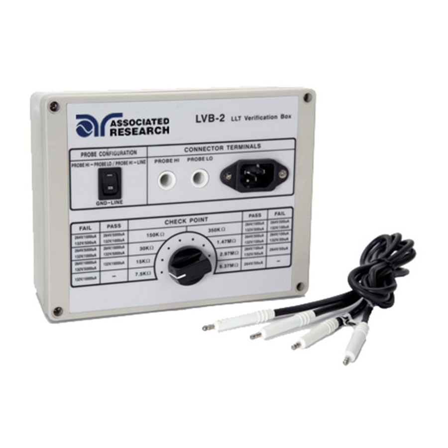
LVB-2 Technical Specifications LVB-2 Instruction Sheet INPUT Voltage 277V MAC through LLT Tester Probe L, N, GND, PH, PL CONNECTOR TERMINAL L, N, GND AC Socket PH, PL Alden Connector PROBE CONFIGURATION GND - LINE PROBE HI - LINE PROBE HI - PROBE LO PROBE CONFIGURATION SWITCH GND - LINE ON/OFF by 10A power switch PROBE HI - LINE ON/OFF by 10A power switch... - Page 4 FAIL 30kΩ 1. LLT: 132VAC, 2000uA High Limit 2. Maximum Voltage 277VAC 3. Ground = Open, Neutral = Closed, Reverse = Off PASS 350kΩ 1. LLT: 132VAC, 500uA High Limit 2. Maximum Voltage 277VAC 3. Ground = Open, Neutral = Closed, Reverse = Off FAIL 150kΩ 1. LLT: 132VAC, 500uA High Limit 2. Maximum Voltage 277VAC 3. Ground = Open, Neutral = Closed, Reverse = Off PASS 1.47MΩ 1. LLT: 132VAC, 100uA High Limit 2. Maximum Voltage 277VAC 3. Ground = Open, Neutral = Closed, Reverse = Off FAIL 350kΩ 1. LLT: 132VAC, 100uA High Limit 2. Maximum Voltage 277VAC 3. Ground = Open, Neutral = Closed, Reverse = Off PASS 2.97MΩ 1. LLT: 132VAC, 30uA High Limit 2. Maximum Voltage 277VAC 3. Ground = Open, Neutral = Closed, Reverse = Off FAIL 1.47MΩ 1. LLT: 132VAC, 30uA High Limit 2. Maximum Voltage 277VAC 3. Ground = Open, Neutral = Closed, Reverse = Off PASS 30kΩ 1. LLT: 264VAC, 10,000uA High Limit 2. Maximum Voltage 277VAC 3. Ground = Open, Neutral = Closed, Reverse = Off FAIL 15kΩ 1. LLT: 264VAC, 10,000uA High Limit 2. Maximum Voltage 277VAC 3. Ground = Open, Neutral = Closed, Reverse = Off © Associated Research 2016...
- Page 5 3. Ground = Open, Neutral = Closed, Reverse = Off PASS 1.47MΩ 1. LLT: 264VAC, 500uA High Limit 2. Maximum Voltage 277VAC 3. Ground = Open, Neutral = Closed, Reverse = Off FAIL 350kΩ 1. LLT: 264VAC, 500uA High Limit 2. Maximum Voltage 277VAC 3. Ground = Open, Neutral = Closed, Reverse = Off PASS 2.97MΩ 1. LLT: 264VAC, 100uA High Limit 2. Maximum Voltage 277VAC 3. Ground = Open, Neutral = Closed, Reverse = Off FAIL 1.47MΩ 1. LLT: 264VAC, 100uA High Limit 2. Maximum Voltage 277VAC 3. Ground = Open, Neutral = Closed, Reverse = Off PASS 6.37MΩ 1. LLT: 264VAC, 30uA High Limit 2. Maximum Voltage 277VAC 3. Ground = Open, Neutral = Closed, Reverse = Off FAIL 2.97MΩ 1. LLT: 264VAC, 30uA High Limit 2. Maximum Voltage 277VAC 3. Ground = Open, Neutral = Closed, Reverse = Off Safety Environment 0° - 40° C Dimensions (W x H x D) 186mm x 75 x 146 Weight 1.3 lbs. STANDARD ACCESSORIES Power Cord (10A) © Associated Research 2016...
-
Page 6: Maintenance
Avertissement des tensions dangereuses qui peuvent être présentes Note: pay close attention to the maximum voltage and duty cycle limitations of each resistor. Applying voltages that are higher than the recommended maximum setting or duty cycles greater than indicated can cause damage to the LVB-2. Note: attention à la tension maximale et les limites du cycle de travail de chaque résistance. L’application de tensions plus élevées que le réglage maximum recommandé ou cycles de travail supérieures à celles indiquées peut causer des dommages à la LVB-2 WARNING The LVB-2 works with test voltages and currents which can cause harmful or fatal electric shock. To prevent accidental injury or death, these safety procedures must be strictly observed when handling and using the test instrument. Les tensions et les courants qui peuvent causer des chocs électriques dangereux ou fatal. Pour éviter les blessures accidentelles ou la mort, ces procédures de sécurité doivent être strictement observées lors de la manipulation et l’utilisation de l’instrument de test © Associated Research 2016... -
Page 7: General Information
CAUTION: Never connect LVB-2 to any mains circuit directly ATTENTION: Ne jamais connecter directement le LVB-2 à un circuit d’alimentation. General Information The LVB-2 is a load box used for the following applications: • Verifying that the failure detectors for a leakage current test sequence of your Associated Research electrical safety testing instrument are functioning properly. • Verifying failure limit thresholds for a leakage current test. • Verifying the three probe configurations of the instrument (G-L, PH-L and PH-PL) are functioning properly. The LVB-2 consists of loads based on the 132V/264V test voltages and failure limits listed in the IEC60601-1 test stan- dard for different types of leakage tests. - Page 8 LVB-2 Instruction Sheet The LVB-2 load box consists of resistors designed to induce a PASS or FAIL condition: • The Check Point knob position determines which resistor is set in the LVB-2 • Each check point has a PASS and FAIL condition. • For a list of all PASS and FAIL condition test settings, refer to the LVB-2 Technical Specifications table. • There is no PASS condition for the 7.5kΩ check point. • There is no FAIL condition for the 6.37MΩ check point The Probe Configuration switch can be set to two different positions depending on the verification type. Figure 2 shows the two different settings of the switch. This setting should match with the Probe Configuration setting on the Leakage Current test instrument. An example of the Probe Configuration setting on the OMNIA 2 is shown in Figure 3 along with the corresponding leakage test type. Figure 2 – Probe Configuration Switch Positions © Associated Research 2016...
- Page 9 LVB-2 Instruction Sheet On the test instrument the Probe Configuration is programmed depending on the type of leakage test needed to be performed. The figure below shows Figure 3 - OMNIA 2 Probe Configuration Setup Instrument Connections (OMNIA 2) The diagram below shows all the connections needed to be made between the OMNIA 2 and the LVB-2: 1. DUT Output connections - Line, Neutral and Ground of the DUT outputs connect to the DUT adapter box. 2. DUT Adapter box – DUT adapter box for connection of Line, Neutral and Ground to the LVB-2 connector terminal. 3. L, N and G connections – This is the socket for the standard IEC320 connector. The line cord from the DUT adapt- er box connects these ports for making the Line, Neutral and Ground connections to the LVB-2 box. 4. Probe connections (OMNIA 2) – Probe Hi and Probe Lo ports on the OMNIA 2. 5. Probe connections (LVB-2) – Probe Hi and Probe Lo connections on the LVB-2. © Associated Research 2016...
-
Page 10: Test Setup
LVB-2 Instruction Sheet Test Setup To setup a test, connect the DUT outputs (L, N and G) of the leakage instrument to the line cord connector on the LVB-2. The two probe connections will also need to be made between the instrument and the LVB-2 for the verifi- cation of additional leakage test types. Program a test sequence based on the parameters listed on the test box for each load type. Select the appropriate Probe Configuration on the LVB-2 using the Probe Confguration switch. Refer to the specifications table and use the rotary switch to select the appropriate Check Point by rotating it clockwise or counter-clockwise: Ensure that the settings on your electrical safety tester are less than or equal to the maximum recommended voltage, current and duty cycle settings of the LVB-2. For each Check Point a PASS test and a FAIL test will be needed to programmed into the leakage test instrument for the pass/fail verifcation. When all connections have been made and the appropriate test programmed in the instrument, press the TEST button to begin the test. With the correct settings entered into the leakage test instrument, the leakage test instrument should record a failure for the FAIL settings and a pass for the PASS settings.
Need help?
Do you have a question about the LVB-2 and is the answer not in the manual?
Questions and answers