Associated Research OMNIA II 8204 Operation And Service Manual

Associated Research OMNIA II 8204 Operation And Service Manual

Electrical safety compliance analyzer
Table of Contents

Advertisement

Quick Links

AC/DC HIPOT WITH INSULATION RESISTANCE TESTER, GROUND BOND, AND
825x INCLUDES 500VA OUTPUT CAPABILITY
82x6 INCLUDES RUN TEST AND LEAKAGE CURRENT TEST
82x7 INCLUDES 500VA AC POWER SOURCE
OPERATION AND SERVICE MANUAL
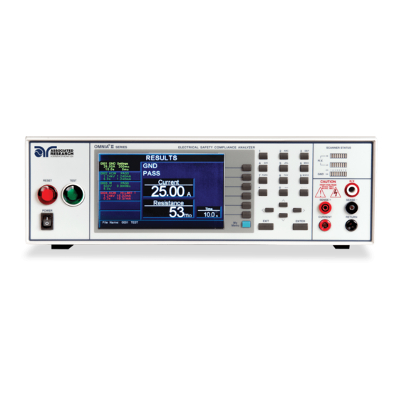
OMNIA II models 8204/8254
OMNIA II models 8206/8256
OMNIA II models 8207/8257
Electrical Safety Compliance Analyzer
CONTINUITY TESTER
SERIAL NUMBER
Item 39334 Ver 3.21
January 4
Associated Research
28105 North Keith Drive - Lake Forest, IL 60045 USA
T. 1-847-367-4077 F. 1-847-367-4080
info@arisafety.com
th
, 2021
www.arisafety.com

Advertisement

Table of Contents
loading
Need help?

Need help?

Do you have a question about the OMNIA II 8204 and is the answer not in the manual?

Questions and answers

Summary of Contents for Associated Research OMNIA II 8204

  • Page 1 82x6 INCLUDES RUN TEST AND LEAKAGE CURRENT TEST 82x7 INCLUDES 500VA AC POWER SOURCE SERIAL NUMBER Item 39334 Ver 3.21 January 4 , 2021 Associated Research 28105 North Keith Drive - Lake Forest, IL 60045 USA T. 1-847-367-4077 F. 1-847-367-4080 info@arisafety.com www.arisafety.com...
  • Page 2 Polybrominated biphenyls (PBB), Polybrominated diphenyl ethers (PBDE), Deca-BDE included. Last two digits of the year in which the CE marking was affixed: 12 The technical file and other documentation are on file with Associated Research, Inc. ______________________________ Joseph Guerriero, President Associated Research, Inc.
  • Page 3: Table Of Contents

    TABLE OF CONTENTS 1. INTRODUCTION ....................1 1.1. Warranty Policies ...................1 1.2. Safety Symbols ....................3 1.2.1. Product Marking Symbols ..............3 1.2.2. Caution and Warning Symbols ............3 1.3. Glossary of Terms ..................3 1.4. Safety ......................5 1.4.1. Service and Maintenance ..............5 1.4.2. Test Operator ..................6 1.5.
  • Page 4 4.3.6. Fail Stop ....................57 4.4. Test Parameters ..................58 4.4.1. Description of Test Parameters ............58 4.4.2. Default Parameters ................62 4.5. Setting Up a Test ..................65 4.5.1. AC Withstand ..................68 4.5.2. DC Withstand ..................69 4.5.3. Insulation Resistance ................71 4.5.4. Continuity .....................72 4.5.5. AC Ground Bond ................72 4.5.6.
  • Page 5 7.2.2. GPIB Address ...................112 7.3. Interface Functions ..................112 7.4. USB / RS-232 / GPIB Interface Command List ........113 7.4.1. Echo and Response Considerations ..........113 7.4.2. Test Execution Commands ............113 7.4.3. File Editing Commands ..............114 7.4.4. Test Parameter Editing Commands and Companion Queries .122 7.4.5.
  • Page 6 10.5.19. Calibration of Run Test Leakage ..........211 10.5.20. Calibration of LCT MD V-Offset ..........211 10.5.21. Calibration of LCT MD Volts DC x 0.1 ........212 10.5.22. Calibration of LCT MD Volts DC x 1 .........212 10.5.23. Calibration of LCT MD Volts DC x 4 .........212 10.5.24.
  • Page 7: Introduction

    1. INTRODUCTION 1.1. Warranty Policies Ikonix USA, certifies that the tester listed in this manual meets or exceeds published manufacturing specifications. This tester was calibrated using standards that are traceable to the National Institute of Standards and Technology (NIST). Your new tester is warranted to be free from defects in workmanship and material for a period of (5) years from date of shipment.
  • Page 8 **This Page Intentionally Left Blank**...
  • Page 9: Safety Symbols

    1.2. Safety Symbols 1.2.1. Product Marking Symbols Product will be marked with this symbol when it is necessary to refer to the operation and service manual in order to prevent injury or equipment damage. Product will be marked with this symbol when hazardous voltages may be present.
  • Page 10 Direct Current, DC: Current that flows in one direction only. The source of direct current is said to be polarized and has one terminal that is always at a higher potential than the other. Frequency: The number of cycles an AC waveform repeats over time. Usually given in Hertz (Hz). Ground: Refers to the point of low potential in a circuit to which all other voltages are referenced.
  • Page 11: Safety

    LAKE FOREST, IL 60045-4546 U.S.A. FAX: 1 (847) 367-4080 E-MAIL: info@asresearch.com Service Interval Associated Research, Inc. will not be held liable for injuries suffered if the instrument is not properly maintained and safety checked annually. See section 1.1. Warranty Policies for more information.
  • Page 12: Test Operator

    1.4.2. Test Station Location Select an area away from the mainstream of activity where employees do not walk while performing their normal duties. If this is not practical because of production line flow, then the area should be roped off and marked for HIGH VOLTAGE TESTING. No employees other than test operators should be allowed inside.
  • Page 13 Do not touch the device under test, high voltage test lead, alligator clip, or clip insulator once the test has been started. Do not touch the front panel when testing or after a malfunction has occurred. Rules Operators should be thoroughly trained to follow all national safety standard guidelines for electrical safety testing in the workplace.
  • Page 14: Key Features Of Omnia Ii

    1.5. Key Features of OMNIA II COLOR TFT DISPLAY 800 x 480 color TFT display (30% larger than the OMNIA 1 series) makes setting up test files, viewing results and performing tests easier than ever. Color coded test steps clearly indicate pass/fail conditions.
  • Page 15: Getting Started

    2. GETTING STARTED Introduction This section contains information for the unpacking, inspection, preparation for use and storage of your Associated Research, Inc., product. 2.1. Unpacking and Inspection 2.1.1. Packaging Your instrument was shipped in a custom foam insulated container. If the shipping carton is damaged, inspect the contents for visible damage such as dents, scratches or a broken display.
  • Page 16 Inside the carton should be the following: DESCRIPTION AR PART NUMBER OMNIA Instrument 8204, 8254, 8206, 8256, 8207, 8257 High Voltage Cable 04040A-08 (3 for 82x6 and 82x7) High Current Output Cable 38489 High Current Return Cable 38490 High Current Test Lead CBLHC40-10TL (82x6 and 82x7) Fuse 38503, 10A Slow-Blow 250VAC...
  • Page 17: Installation

    2.2. Installation 2.2.1. Work Area Locate a suitable testing area and be sure you have read all safety instructions for the operation of the instrument and suggestions on the test area setup in section 1.4. Safety. Make sure the work area you choose has a three-prong grounded outlet capable of supplying the necessary input current to the power source.
  • Page 18: Environmental Conditions

    The instrument is shipped with a line cord containing a protective earth ground. When the line cord is connected to an appropriate AC power source the cable will connect the chassis to earth ground. The main plug shall only be inserted in a socket outlet with a protective ground (earth) contact.
  • Page 19 More Information For more information on test operator and workstation safety please visit the Events and Training section of our website at http://www.asresearch.com/events- training/Default.aspx...
  • Page 20: Specifications And Controls

    3. SPECIFICATIONS AND CONTROLS 3.1. OMNIA II Functional Specifications INPUT 115 / 230V auto-range,  15  variation Voltage 50/60 Hz  5% Frequency 115 VAC, 230VAC – 10A Slow-Blo 250VAC Fuse DIELECTRIC WITHSTAND TEST MODE Output Rating 5KV @ 50mA AC 5KV @ 100mA AC (Models 825x) 6KV @ 20 mA DC Voltage Setting...
  • Page 21 DIELECTRIC WITHSTAND TEST MODE (CONT.) Current Display Auto Range* 0.000 mA – 3.500 mA RMS AC Total Range 1: (0.000 mA – 5.500 mA Peak) Resolution: 0.001 mA 3.00 mA – 50.00 mA RMS Range 2 (5.00 mA – 70.07 mA Peak) AC Real Resolution: 0.01 mA ...
  • Page 22  (0.1 + 0.05 sec) Accuracy: Short Circuit Minimum current 100mA peak (200mA, Models 825x) at Protection short circuit, response time < 2ms *Autorange operation: Ranges up to higher range when Peak OR RMS values are greater than range maximum Ranges down to lower range when Peak AND RMS values are less than range minimum...
  • Page 23 INSULATION RESISTANCE TEST MODE 30 – 1000 VDC Voltage Setting Range: Resolution: 1 V  (2% of setting + 2 counts) Accuracy: Charging Maximum >20mA peak Current 0 – 1000 V Voltage Display Range: Resolution: 1 V  (2% of reading + 2 counts) Accuracy: 0.05M...
  • Page 24 GROUND BOND TEST MODE 3.00 – 8.00 VAC Output Voltage Range: (Open Circuit Limit) Resolution: 0.01 V  (2 % of setting + 0.03V) O.C. Condition Accuracy: Output Frequency Range: 60 or 50 Hz, user selectable  0.1% Accuracy: 1.00 – 40.00 A Output Current Range: Resolution: 0.01 A...
  • Page 25 CONTINUITY TEST MODE DC 0.1A  0.01A Total Resistance*:0.00 – 12.0 Output Current DC 0.01A  0.001A Total Resistance*:12.1 – 120 DC 0.001A  0.0001A Total Resistance*:121 – 1200 DC 0.0001A  0.00001A Total Resistance*:1201 – 10000 0.00 – 10.00  Resistance Range 1: Resolution: 0.01 ...
  • Page 26 8 channel high voltage and high current switching matrix. Why use the term “Counts”? Associated Research publishes some specifications using COUNTS which allows us to provide a better indication of the tester’s capabilities across measurement ranges. A COUNT refers to the lowest resolution of the display for a given measurement range.
  • Page 27 RUN TEST MODE (MODELS 82X6 AND 82X7) DUT POWER 0 – 277 VAC Single Phase Unbalanced Voltage (One Hot or Line conductor and One Neutral) Current 16AAC max continuous 0.0 – 277.0 VAC Full Scale Voltage Display Range: Resolution: 0.1 V ...
  • Page 28 RUN TEST MODE (MODELS 82X6 AND 82X7) 0.000 – 1.000 Power Factor Range: Resolution: 0.001  (8% of reading + 2 Counts) Accuracy: 0.00 – 10.00 mA Leakage Current Range: Resolution: 0.01 mA  (2 of reading + 2 Counts) Accuracy: Leakage current measuring resistor MD = 2K...
  • Page 29 Surface to Surface (PH – PL) Surface to Line (PH – L) Ground to Line (G – L) LEAKAGE LIMIT SETTING Range: 0.0uA ~ 999.9uA Touch Current High Limit (RMS) 1000uA ~ 10.00mA Resolution: 0.1uA / 1uA / 0.01mA Range: 0.0uA ~ 999.9uA Touch Current Low Limit (RMS) 1000uA ~ 10.00mA...
  • Page 30 DISPLAY (CONT.) 400uA ~ 2100uA, frequency Range 4 DC, 15Hz - 1MHz Resolution DC , 15Hz < f <100KHz: ±(2% of reading + 3counts) Accuracy 100KHz < f < 1MHZ : ±5% of reading (10uA - 8500uA) 1800uA ~ 8500uA, frequency Range 5 DC, 15Hz - 1MHz Resolution...
  • Page 31 DISPLAY (CONT.) 400uA ~ 2100uA, frequency DC Range 4 - 1MHz Resolution DC : ±(2% of reading + 2uA) Accuracy 15Hz < f < 1MHZ : ±10% of reading + 2uA 1800A ~ 8500uA, frequency DC Range 5 - 1MHz Resolution DC : ±(2% of reading + 2uA) Accuracy...
  • Page 32 AC SOURCE 500VA OUTPUT Power 630VA and 500W Maximum Voltage 0 - 150.0V / 0 - 277.0V 4.20A maximum for 0-150V range / 2.10A maximum 0- Current 277V range ≤ 1% at 45-500Hz and output voltage within the 80~140Vac Distortion at Low Range or the 160~277Vac at High Range.
  • Page 33: Instrument Controls

    3.2. Instrument Controls 3.2.1. Front Panel Controls 1. RESET BUTTON: Resets the instrument. If a failure condition occurs during a test, pressing this button will reset the system, shut off the alarm and clear the failure condition. The Reset button must be pressed before performing another test or changing any of the setup parameters.
  • Page 34 follows: Setup Tests, Perform Tests, Results Summary, and Results. 11. ENTER KEY: Key used to finalize parameter entries. The ENTER key may also be used to scroll the highlighted area to different parameters in the parameter setting screens. 12. SENSE + TERMINAL: Connector used to attach the + sense lead for 4-wire Kelvin current measurement.
  • Page 35: Rear Panel Controls

    3.2.2. Rear Panel Controls 1. CALIBRATION BUTTON: To put the instrument into the calibration mode push this button and turn on the power switch simultaneously. 2. SCANNER CONNECTOR: For connection of optional external Scanner. 3. REMOTE SIGNAL OUTPUT: 9-Pin D sub-miniature female connector for monitoring PASS, FAIL, and PROCESSING output relay signals (See section 6.0.
  • Page 36: Additional Rear Panel Controls

    10. SCANNER OUTPUTS : Optional scanner matrix that provides 8 HV/Return connections and 8 Ground Bond connections. Please refer to the Options section of this manual for additional connection information 3.2.3. Additional Rear Panel Controls Models 82x6 and 82x7 1. DUT POWER INPUT CONNECTOR: This connector provides the Line and Neutral input power connections on pin 1 and 2 respectively.
  • Page 37 Resistance tests. During a Run test or Leakage Current test, this terminal is isolated from the test circuits. 6. GND: Connector used to attach the adapter box Ground or Earth lead to the instrument. 7. PROBE HI: Connector used to attach the Probe-HI test lead to the DUT. When used with an appropriate test lead, this terminal connects one side of the MD (measuring device) to the DUT during Enclosure or Applied Part Leakage Current tests.
  • Page 38: Programming Instructions

    4. PROGRAMMING INSTRUCTIONS 4.1. Power Up The OMNIA automatically defaults to the Main Menu screen upon power up. The Main Menu screen will appear as follows: From the Main Menu screen five menus screens may be accessed: Setup System, Setup Tests, Perform Tests, FailCHEK and Information 4.2.
  • Page 39: Setup System Keys

    4.2.1. Setup System Keys Soft Keys In the Setup System screen, the soft keys correspond to several setup screens. Use the soft keys to enter the corresponding system screen. Once a system screen has been entered, the soft keys can be used to edit parameters. Press the soft key to edit the corresponding parameter.
  • Page 40 Set Date From the Time and Date Setting screen, highlight the Set Date parameter by using the left and right arrow keys. Within the Set Date parameter are three separate fields: month, day, and year. Using the left and right arrow keys select the field within the date that you want to edit. Using the numeric keypad enter the new number.
  • Page 41 Set Day From the Time and Date Setting screen, press the “Set Day” soft key. As the soft key is pressed, the “Set Day” pop up screen will appear as follows: Use the up or down arrow keys to select the day of the week. Once a parameter is edited, it is necessary to complete the edit either by pressing the ENTER key to accept the new value or the EXIT key to escape from the edit and return to the original value.
  • Page 42: Calibration Alert

    Use the up or down arrow keys to select the date format. Once a parameter is edited, it is necessary to complete the edit either by pressing the ENTER key to accept the new value or the EXIT key to escape from the edit and return to the original value.
  • Page 43 Calibration Due Date It is recommended that calibration should be performed at least once a year. It is recommended that the Calibration Due Date not bet set greater than one year from the Calibration Date displayed. From the Calibration Alert Setting screen, highlight the Calibration Due parameter by using the left or right arrow keys.
  • Page 44: Hardware

    pressing the ENTER key to accept the new number or the EXIT key to escape from the edit and return to the original number. The Calibration Alert Warning screen appears as follows: At the Calibration Alert Warning screen there are three options: “Show this screen again?”, Password, and OK.
  • Page 45 Smart GFI (Ground Fault Interrupt) The high voltage power supply of the OMNIA is internally referenced to earth ground. Since the leakage current measuring circuit of the instrument monitors only current that flows through the return lead the possibility exists for current to flow directly from the high voltage output to earth ground without being measured.
  • Page 46 Continuity Scanner (8204) This selection will only be available if option 01: Internal Scanner is installed on the unit. For more information on this option, please refer to section 8. Options. You may toggle between the HV Channel (High Voltage) and GND Channel (Ground Bond) selection by pressing the “Continuity Scanner”...
  • Page 47: Security

    DUT-HV Setup (82x6 and 82x7) The DUT-HV selection activates an additional parameter in the AC Withstand, DC Withstand and IR Tests parameter screens. The additional parameter is called “DUT Output” and its function is to control the high voltage relay at the DUT output. When the DUT Output parameter is turned ON during an AC Withstand, DC Withstand, or IR test, high voltage will be present at the DUT outputs as well as the front and rear panel HV connectors.
  • Page 48 Security From the Security screen you may turn the Security function ON and OFF by pressing the “Security” soft key. Selecting Security OFF disables all security features and User ID settings. Selecting security ON restricts access to parameter settings. The level of security is determined by the User Setup function.
  • Page 49 From the User Setup screen, you can view the list of users currently setup and the associated security level. The OMNIA will have a default User ID named ADMIN with Full System Access security level. This User ID cannot be deleted. Add User From the User Setup screen, press the Add User soft key.
  • Page 50 Confirm Password In order to complete the password entry, the password must be confirmed by retyping the password into the Confirm Password parameter. To confirm the password, use the up and down arrow keys to select the Confirm Password parameter. Use the alpha/numeric keypad to retype the password.
  • Page 51 NOTE: whenever a user’s security level is Run Only, you may only start at test step 1. Recall Setups: This mode allows the user to load previously configured test files but it does not allow any editing of the parameters. In this mode the user is restricted from access to the "Setup Test Parameters"...
  • Page 52 deleted, it cannot be recovered. The User ID must be recreated by adding a new user. Please refer to the “Add User” section above for more information. Forgotten Password If you have forgotten your password you may access a User ID by typing in the number “8000”...
  • Page 53 Language From the User Interface screen, press the “Language” soft key. As the soft key is pressed, the “Language” pop up screen will appear as follows: Use the up or down arrow keys to select the preferred language setting for the unit. The language options are English, Traditional Chinese, Simplified Chinese, Spanish, Portuguese, Turkish, German and French.
  • Page 54 Use the up or down arrow keys to select the preferred color style setting for the unit. The color style setting options are Basic, Granite, Arctic and Midnight. Once a parameter is edited, it is necessary to complete the edit either by pressing the ENTER key to accept the new value or the EXIT key to escape from the edit and return to the original value.
  • Page 55 2.) Press the “System Settings” soft key. 3.) Press the “User Interface” soft key. 4.) Use the up arrow key to scroll to the English setting.
  • Page 56: Power-On Screen

    5.) Press the Enter key to confirm. 4.2.7. Power-On Screen You may configure the OMNIA to power-on at the Main Menu screen, the Perform Tests screen or the My Menu screen. From the User Interface screen, press the “Power-On Screens” soft key. The Power-On Setting screen will now be displayed. From the Power-On Setting screen, two different parameters may be accessed: Animation and Home Screen.
  • Page 57 up or CONTINUE through to the next screen after the Animation screen is displayed for four seconds or SKIP the Animation screen completely. The option to PAUSE, CONTINUE or SKIP may be selected by pressing the “Animation” soft key. When PAUSE is selected, the words “Press any key to continue”...
  • Page 58: Setup Tests Menu

    Use the up or down arrow keys to select the preferred home screen setting for the unit. The home screen setting options are Menu, Perform Tests and My Menu. Configure OMNIA to go directly to the Perform Test screen 1. Set OMNIA Animation to CONTINUE or SKIP. 2.
  • Page 59: Add

    The Setup Tests screen is the central starting point for programming tests into the instrument. From this screen, test parameters are entered and edited, and the order of the test steps can be arranged and then stored to test files. The OMNIA is capable of performing a 10,000-step sequential test from a single test file.
  • Page 60: Edit

    For a detailed description of how to set up a test sequence, please refer to section 4.5. Setting Up a Test. For a detailed description of the screens and parameters that are associated with test selection soft keys on this screen please refer to section 4.4. Test Parameters. 4.3.2.
  • Page 61: Prompt

    Press ENTER to confirm and delete the selected step or EXIT to cancel and return to the Setup Tests screen. 4.3.4. Prompt The Prompt function allows you to insert a short line of text in a step. The Prompt will appear on the screen before the step is initiated and remain on the screen until the TEST button is pressed.
  • Page 62: File

    To enter a text prompt, use the alphanumeric keypad. At the text prompt edit, the letter or symbol will be inserted at the point where the cursor is flashing. The cursor will then increment to the next position and wait for an additional character insertion. If you make a mistake or want to change the character, press the backspace key in the alphanumeric keypad.
  • Page 63: Fail Stop

    Save To save a file with its current name press the “Save” soft key from the File Setup screen. Save As To save an edited file without overwriting the original or to give a file a new name, press the “Save As” soft key from the File Setup screen. The Create File screen will now be displayed.
  • Page 64: Test Parameters

    Fail Stop with Run and Leakage Current tests Associated Research recommends performing a Hipot test with the Fail Stop ON prior to performing a Run Test or Leakage Current test. Performing a Hipot test first can detect if a DUT is shorted line to ground before applying line power to it.
  • Page 65 Amp-HI: The current high limit that will cause a failure if exceeded during a RUN test. Amp-LO: The current low limit that will cause a failure if not exceeded during a RUN test. Power-HI: The power high limit that will cause a failure if exceeded during a RUN test. Power-LO: The power low limit that will cause a failure if not exceeded during a RUN test.
  • Page 66 Ramp Down: The length of time that is allowed for the test voltage to decay from programmed test voltage to 0. Arc Sense: During hipot testing some low current arcing may be allowable. Arc sense is a maximum allowable threshold for arcing. Arc Detect: If the Arc Fail mode is set to ON, the program will indicate an arc failure when the arc current is exceeds this setting.
  • Page 67 Select Meter: This parameter allows you to select the meter orientation during testing. Step Name: This parameter allows you to enter a text name for each step. Leakage: This parameter allows you to measure leakage using either Peak or RMS measurements.
  • Page 68: Default Parameters

    4.4.2. Default Test Parameters In each of the Test Parameter Setting screens there is a “Defaults” soft key. When this key is pressed the test will load with a set of predetermined Default Parameters. The following table is a listing of the Default Parameters for each of the different types of tests that are available in the OMNIA II.
  • Page 69 TEST TYPE PARAMETER VALUE Voltage 1200VDC HI-Limit 10000A LO-Limit 0.0A Ramp Up 0.4s Dwell Time 1.0s Ramp Down 1.0s Charge-LO 0.0A Arc Sense Offset 0.0uA Scanner OOOOOOOOOOOOOOOO Ramp-HI Arc Detect Continuity Voltage 500VDC HI-Limit 0.00M LO-Limit 0.05M Ramp Up 0.1s Dwell Time 0.5s Delay...
  • Page 70 TEST TYPE PARAMETER VALUE Setup Sys. PLC Remote Address (GPIB only) Measurement True RMS Language English Volume Step Name Color Style Arctic Smart GFI 0.4mA Security User ID Admin Password 8000 Security MODELS 82X6 AND 82X7 Run Test Voltage-HI 100.0V Voltage-LO 0.0V Amp-HI...
  • Page 71: Setting Up A Test

    4.5. Setting Up a Test Upon power up, OMNIA will initialize with the test file that was last used before power down. If the instrument is new it will come loaded with one default file that the instrument will boot up with until it is changed. 1.
  • Page 72 escape from the edit and return to the original number. 9. Press the EXIT key to “Add” this test to the sequence of tests. The Setup Tests screen will now be displayed again, this time with the new parameters. 10. At this point, you may add more tests to the sequence, insert tests, insert prompts, perform the test sequence, or store the sequence to the file name you created.
  • Page 73 screen will now be displayed along with a pop-up message that appears as follows: Pressing the ENTER key will store the file with the file name you gave it and go to the Perform Test screen. You may now perform a test (refer to section 5.2. Perform Tests Menu).
  • Page 74: Ac Withstand

    The instrument is now ready to perform tests with the new file. You may now press the ENTER key to go to the Perform Tests screen or press the EXIT key to return to the Main Menu. Inserting Tests From the Setup Tests screen, scroll the highlighted area to the step in the sequence where you would like to insert a test.
  • Page 75: Dc Withstand

    From the AC Withstand Parameter Setting screen the following parameters may be controlled: Voltage, HI-Limit Total, LO-Limit Total, Ramp Up, Dwell Time, Ramp Down, Arc Sense, HI-Limit Real, LO-Limit Real, Offset, Frequency, Arc Detect (ON/OFF), Step Name, Scanner Channel, Defaults and More. Pressing the More soft key will display the additional parameters Continuity selection (DC continuity or OFF) and Select Meter.
  • Page 76 From the DC Withstand Parameter Setting screen the following parameters may be controlled: Voltage, HI-Limit, LO-Limit, Ramp Up, Dwell Time, Ramp Down, Charge- LO, Arc Sense, Offset, Ramp-HI (ON/OFF), Arc Detect (ON/OFF), Continuity (DC continuity or OFF), Scanner Channel, Step Name and More. Pressing the More soft key will display the additional parameter Defaults.
  • Page 77: Insulation Resistance

    show the word “READING” and then the display the new value. The new value is automatically updated in the field and does not allow an escape to the original value or require that the ENTER key be used to accept the new parameter. Ramp-HI The Ramp-HI function is active during the Ramp period only.
  • Page 78: Continuity

    new Charge-LO current via the numeric keypad and then press the ENTER key to accept the new parameter or press the EXIT key to escape from the edit. To automatically set the Charge-LO current, use the up and down arrow keys or the ENTER key and scroll the highlighted area to the Charge-LO current parameter.
  • Page 79 From the Ground Bond Parameter Setting screen, the following parameters may be controlled: Current, Voltage, HI-Limit, LO- Limit, Dwell Time, Offset, Scanner Channel, Frequency, DualCHEK, Step Name and Defaults. Offset This function allows the instrument to compensate for lead and test fixture resistance during a Ground Bond or Continuity test.
  • Page 80: Continuity

    Use the up or down arrow keys to select the DualCHEK setting for this test. The DualCHECK setting options are ACW, DCW or OFF. Once a parameter is edited, it is necessary to complete the edit either by pressing the ENTER key to accept the new value or the EXIT key to escape from the edit and return to the original value.
  • Page 81: Functional Run Test (Model 82X6 And 82X7)

    ENTER key be used to accept the new parameter. 4.5.7. Functional Run Test (Models 82x6 and 82x7) Associated Research recommends performing a Hipot test with the Fail Stop ON prior to performing a Run Test or Leakage Current test. Performing a Hipot test first can detect if a DUT is shorted line to ground before applying line power to it.
  • Page 82 Setting screen will appear as follows: From the Run Test Parameter Setting screen, the following parameters may be controlled: Voltage-HI, Voltage-LO, Amp-HI, Amp-LO, Dwell Time, Delay Time, Leakage-HI, Leakage-LO, Power-HI, Power-LO, PF-HI and PF-LO, AC Source, Active Link, Select Meter and Step Name. PF (Power factor) Power Factor = W/VA where W =Watts (Real Power) and VA =Volts x Amps (apparent power).
  • Page 83 When the Leakage-HI trip limit is set to 0, S2 is placed in position 2 which disables the earth leakage test and connects the neutral of the DUT input to the ground of the DUT. AC Source Press the “AC Source” soft key to enter the AC Source Test Parameter screen. The screen will look as follows:...
  • Page 84: Leakage Current Test (Models 82X6 And 82X7)

    AC source. 4.5.8. Leakage Current test (Models 82x6 and 82x7) Associated Research recommends performing a Hipot test with the Fail Stop ON prior to performing a Run Test or Leakage Current test. Performing a Hipot test first can detect if a DUT is shorted line to ground before applying line power to it.
  • Page 85 The Omnia II applies a formula for taking an offset into account: Displayed Current = √((Total Leakage Current)^2 – (Offset Current)^2) The “Total Leakage Current” is the measure of the total leakage current on the system including the Omnia II, other integrated Associated Research, Inc. instruments and the...
  • Page 86 The instrument then calculates the vector sum of the offset value and the total value so that the inherit leakage of the Associated Research, Inc. instruments is excluded from the measurements. Line Configuration Soft keys The LINE configuration is determined by the relays S1, S2 and S3 (see Figure below) and is set using the corresponding Line Configuration Soft keys.
  • Page 87 conditions. The different combinations are represented in the table below.
  • Page 88 LINE NEUTRAL REVERSE GROUND CONFIG. Relay/ Fault Soft key Relay Fault Relay/ Fault Soft Soft key Open Open Open Open Open Closed Open Closed Closed Open Closed Open Closed Closed Closed Closed Probe Configuration The Probe configuration is controlled by the relays SH and SL shown in Figure 2 and are set by the “Probe”...
  • Page 89 Ground-to-Line indicates the MD is connected to measure the leakage current in the line cord from the earth ground conductor back to the system neutral. This is referred to as an PROTECTIVE CONDUCTOR CURRENT TEST. Probe-HI to Line indicates the MD is connected between the PROBE HI terminal on the instrument, which should be connected to the ENCLOSURE of the DUT, and the system neutral.
  • Page 90 Measuring Device The Measuring Device is an impedance circuit that simulates the human body. The Measuring Device is specified differently for different applications and specifications. Repeatedly pressing the “Measure Device” soft key will allow you to select one of the many measuring devices listed in the table below.
  • Page 93 External Measuring Device The OMNIA 8206 and 8207 have an access panel on the back of the instrument that can be removed to access the MD external PCB. The MD external PCB may be configured for a simple resistive measuring device. No components are supplied for the population of the PCB.
  • Page 94 Frequency Check The Leakage Current test can be configured to verify the bandwidth of the leakage current “voltmeter” by setting the Probe configuration to “Probe-HI to Probe-LO” and selecting the medical device “Frequency Check”. The selection is intended for meter verification purposes only and has no application for normal testing.
  • Page 95 From this screen, you can control the following test parameters: Voltage, Frequency, A-Hi, Output N/G, Volt Range and OC-Fold. The A-Hi parameter allows you to set the AC Source high current limit. The Output N/G parameter allows you to configure the AC Source output to either open or close the ground connection.
  • Page 96: Setting Up A Test

    4.6. My Menu From the System Setup screen press the “My Menu” soft key. The My Menu screen appears as follows: The My Menu function allows the user to configure a custom menu. In order to customize a softkey selection, press and hold one of the softkeys until the My Menu pop appears as follows: Use the up or down arrow keys to select the preferred function.
  • Page 97 parameter. DELETE will clear the current softkey selection. Once a parameter is edited, it is necessary to complete the edit either by pressing the ENTER key to accept the new value or the EXIT key to escape from the edit and return to the original value.
  • Page 98: Operating Instructions

    5. OPERATING INSTRUCTIONS 5.1. Instrument Connections The test leads and the adaptor box may be connected to the receptacles located on the front or the back of the OMNIA. The HV, Current, Return, Sense+, and Sense- and receptacles located on the front panel of the OMNIA are wired in parallel with another set located on the back of the instrument.
  • Page 99: Interlock Connector

    The rear output connections may be used for connecting the adapter box as well. Adaptor Box Connections Model 82x6 and 82x7 5.1.3. Interlock Connector OMNIA is equipped with a Remote Interlock feature. Remote Interlock utilizes a set of closed contacts to enable the instrument’s output. If the Remote Interlock contacts are open the output of the instrument will be disabled.
  • Page 100: Scanner Connections

    must be at a low voltage reference potential. The low voltage reference does not need to be physically earth grounded but should not carry any large voltage potential. The 220 - 240V US style line power IS NOT suitable to connect to the DUT inputs. This style of power distribution is a balanced type with two HOT or LINE conductors.
  • Page 101: Perform Tests Menu

    5.2. Perform Tests Menu From the Main Menu screen, press the soft key “Perform Tests”. The Perform Tests Menu will now be displayed. From the Perform Tests screen, four different software controls may be accessed: Single Step (ON/OFF), Fail Stop (ON/OFF), Load File, Results.
  • Page 102: Single Step

    Using the up and down arrow keys, scroll the highlighted area to the File you would like to load and press the “Load” soft key. The file you selected will now load and the screen will revert to the Perform Tests screen. 5.2.2.
  • Page 103: Results

    Fail Stop with Run and Leakage Current tests Associated Research recommends performing a Hipot test with the Fail Stop ON prior to performing a Run Test or Leakage Current test. Performing a Hipot test first can detect if a DUT is shorted line to ground before applying line power to it.
  • Page 104: Performing A Test

    The Results screen will appear as follows: Using the up and down arrow keys, scroll the highlighted area to the step results you wish to review. The left and right arrow keys may be used to page through results if the test contains more than five steps.
  • Page 105 5. If a Prompt is embedded within a step, the test will pause at that step and display the Prompt as a pop-up message. An example of a prompt will appear as follows: 6. In order to clear the Prompt and continue the test, push the TEST button. The highlighted area of the screen remains on the test that is being performed until it is finished.
  • Page 106: Perform Tests Metering

    5.4. Perform Tests Metering Each test performed by the OMNIA contains a unique set of parameters and therefore requires specialized metering for each test. The following table describes what meters will be displayed for each of the different test types. METERING SCREENS 8204/8206/8207 TEST TYPE CURRENT(T) CURRENT(R)
  • Page 107: Test Status Messages (All Models)

    5.5.1. Test Status Messages The following is a complete listing of the messages that appear in the Test status display and an explanation for each. Dwell This message appears on the display while a test is in process, the values update in real time.
  • Page 108 HI-Limit This message appears on the display if the DUT measurement exceeds the HI-Limit setting of any parameter (except AC withstand). LO-Limit This message appears on the display if the DUT measurement drops below the LO- Limit setting of any parameter (except AC withstand). HI-Lmt T This message appears on the display if the DUT leakage current exceeds the HI-Limit setting, of the Total current parameter in AC withstand.
  • Page 109: Error Messages (All Models)

    which will disable the instrument’s output if they are opened before or during a test. Remote Interlock could also be referred to as a remote system lockout, utilizing “fail when open” logic. The Remote Interlock feature may be disabled by plugging the “Interlock Disable Key”...
  • Page 110 This message appears on the display if the DUT input voltage drops below the Volt- LO Trip setting. Amp-HI This message appears on the display if the current exceeds the Amp-HI Trip setting. Amp-LO This message appears on the display if the current drops below the Amp-LO Trip setting.
  • Page 111 Fatal Error screen will appear as follows: This type of failure permanently locks the instrument in the “Fatal Error” mode and requires that the instrument be serviced by Associated Research. The following Fatal Error identification numbers will represent the type of failure that has occurred: Error Code 9001 will appear on the display if the instrument has a recognizable internal component failure.
  • Page 112: Connection Of Remote I/O

    6. CONNECTION OF REMOTE I/O Two 9-pin “D” type connectors mounted on the rear panel provide REMOTE-INPUT- OUTPUT control and information. These connectors mate with a standard 9 pin D- sub-miniature connector provided by the user. The output mates to a male (plug) connector while the input mates to a female (receptacle) connector.
  • Page 113: Remote Signal Inputs And Memory Access

    Pins 1 and 2 provide the PASS signal. Pins 3 and 4 provide the FAIL signal. Pins 5 and 6 provide the PROCESSING signal. Pins 7 and 8 provide the RESET signal. The following describes how the relays operate for each test condition: PROCESSING –...
  • Page 114 parameters and initiate a test remotely. Ten pre-programmed test files can be accessed by connecting pins 1,6,8, and 9 to the common pin 7, in different combinations. The memory select bits should be set simultaneously and remain set for a minimum of 20ms to guarantee that the correct memory will be selected. However, the memory select bits may be set in sequential manner, provided that the time delay between each bit is less than 4ms.
  • Page 115 If the Remote Interlock contacts are opened during a test, the pop-up message will be displayed and the test will abort. The hardware and has been configured to provide the interlock connections on pins 4 and 5 of the Remote Interface, Signal Input port. The instrument can still be used without the external interlock device as long as the Interlock Disable Key (38075 provided with unit) is plugged into the Remote Interface, Signal Input port.
  • Page 116: Bus Remote Interface Usb / Gpib / Rs-232

    7. BUS REMOTE INTERFACE USB / GPIB / RS-232 This section provides information on the proper use and configuration of bus remote interface. The USB/RS-232 remote interface is standard on model 820X but the GPIB (IEEE-488) interface option can be substituted for the USB/RS-232 interface. Please refer to the Option section of this manual for details on the OMNIA options.
  • Page 117: Sending And Receiving Commands

    No parity This interface does not support XON/XOFF protocol or any hardware handshaking. The controller should be configured to ignore the handshaking lines DTR (pin 4), DSR (pin 6) CTS (pin 8) and RTS (pin 7). If the port cannot be configured through software to ignore these lines the handshake lines should be jumpered together in two different sets.
  • Page 118: Gpib Address

    No more than 15 device loads connected to each bus, with no less than two- thirds powered on. For example 1 GPIB controller and a maximum of 14 GPIB instruments. NOTE: A bus extender, which is available from numerous manufacturers, is available to overcome these limitations.
  • Page 119: Usb / Rs-232 / Gpib Interface Command List

    7.4. USB / RS-232 / GPIB Interface Command List 7.4.1. Echo and Response Considerations RS-232 Responses The USB/RS-232 bus will automatically send any response back to the controller's input buffer. GPIB Queries and Responses The OMNIA GPIB bus will not send any data to the controller without being queried. A GPIB read command must be sent after a command string to retrieve any data from a query command (?).
  • Page 120: File Editing Commands

    perform an actual test and all safety precautions should be observed when using this command. SACG Set the Charge-LO parameter for the DCW or IR test. The cables and any test fixture should be connected before executing the command. The test parameters that are set for the step will be used when performing the auto setting.
  • Page 121 COMMAND DESCRIPTION VALUE SP <prompt message> Step Prompt prompt message = Create Valid ASCII (1) maximum 31 characters Step Prompt Delete SF {1|0} Step Fail Stop 1=On, 0=Off (1) "Valid ASCII" is the character set that is available from the front panel LCD user interface.
  • Page 122 CONT, RUN or LCT must be used. The parameters <p1,p2> etc. indicate the individual settings for each test. All parameters must be included with the command and should appear in the same order that is shown on the actual setting screens. The correct order is shown in the tables below.
  • Page 123 CONT Power-HI Meas. Device (UL544NP/UL544P/IEC601U L2601/ UL1563/IEC60990FIG4-U2/ IEC60990FIG5- U3/IEC60990FIG3-U1/ EXTERNAL) Power-LO Probe (Ground To Line/ Probe-HI to Line/Probe-HI To Probe- PF-HI Leakage Mode (Peak/RMS) PF-LO PLC Control Active Link PLC Control DUT Output is only a parameter in the ADD string if DUT HV = ON in the system settings menu Scanner Setup is only a parameter in the ADD string if either a scanner is installed (8204, 8254 w/ option 01) or a slave SC6540 scanner is connected to the Omnia unit.
  • Page 124 ADD IR,1000,0.00,0.05,0.1,1.0,0.0,0.000,OFF,OOOOOOOO Adding a Ground Bond Test ADD GND,Current,Voltage,HI-Limit,LO-Limit,Dwell Time,Offset,Scanner Channel,Frequency ADD GND,25.00,8.00,100,0,1.0,0,0,60 Adding a Continuity Test ADD CONT.,HI-Limit,LO-Limit,Dwell,Offset,Scanner Channel,Continuity ADD CONT.,1000,0.00,1.0,0.00,OOOOOOOO Adding a Functional Run Test ADD RUN,Voltage-HI,Voltage-LO,Amp-HI,Amp-LO,Dwell,Delay,Leakage-HI,Leakage- LO,Power-HI,Power-LO,PF-HI,PF-LO,Active Link,PLC Control ADD RUN,125.0,0.0,10.00,0.00,1.0,0.2,10.00,0.00,1000,0,1.000,0.000,M1 Adding a Leakage Current test ADD LCT,Leakage-HI,Leakage-LO,Voltage-HI,Voltage- LO,Delay,Neutral,Reverse,Ground,Meas.
  • Page 125 and any toggle field that use words or phrases like "OPEN", "CLOSE". The LS2? companion command will also list all parameters in complete text as they appear on the setting screen. Voltage Voltage Voltage HI-Limit T HI-Limit HI-Limit HI-Limit R LO-Limit LO-Limit Ramp Up...
  • Page 126 Voltage Frequency AC/DC A-Hi Ranging Mode Output N/G PLC Control Voltage Volt-Range Frequency OC-Fold A-Hi Output N/G Volt Range OC-Fold Scanner Setup DUT Output is only a parameter in the ADD string if DUT HV = ON in the system settings menu Scanner Setup is only a parameter in the ADD string if either a scanner is installed (8204, 8254 w/ option 01) or a slave SC6540 scanner is connected to the Omnia unit.
  • Page 127 ADD2 GND,Current,Voltage,HI-Limit,LO-Limit,Dwell Time,Offset,Scanner Channel,Frequency,DualCHECK ADD2 GND,25.00,8.00,100,0,1.0,0,0,60,OFF Adding a Continuity Test ADD2 CONT,HI-Limit,LO-Limit,Dwell,Offset,Scanner Channel,Continuity ADD2 CONT.,1000,0.00,1.0,0.00,OOOOOOOO Adding a Functional Run Test ADD2 RUN,Voltage-HI,Voltage-LO,Amp-HI,Amp-LO,Dwell,Delay,Leakage- HI,Leakage-LO,Power-HI,Power-LO,PF-HI,PF-LO,Active Link,PLC Control,Voltage,Frequency,A-Hi,Output N/G,Volt Rang,OC-Fold ADD2 RUN,125.0,0.0,10.00,0.00,1.0,0.2,10.00,0.00,1000,0,1.000,0.000,OFF,M1 Adding a Leakage Current test ADD2 LCT,Leakage-HI,Leakage-LO,Voltage-HI,Voltage-LO,Dwell Time,Offset,Delay Time,Neutral,Reverse,Ground,Meas.Device,Probe,Peak/RMS,Active Link,AC/DC, Ranging Mode,PLC Control,Scanner Setup ADD2 LCT,6000,0.0,125.0,0.0,0.5,1.0,0.0,1.0,CLOSED,OFF,CLOSED,UL544NP, Ground To Line,RMS,OFF,AC+DC,Auto,M1,OOOOOOOO PLC Control is only available if option 04 (3 Remote Memory Send) or option 05 (7 Remote Memory...
  • Page 128: Test Parameter Editing Commands And Companion Queries

    SAA, SAD, SAI, SAG, SAC, SAGA, SAGD, SAL, SAR These commands insert or add a new step to the test sequence. This command will add or insert the test at the step location that has been selected. When a test has already been created at a selected step then the new step will be inserted and the previous step will move down to the next step and all other step will be renumbered accordingly.
  • Page 129 COMMAND NAME TEST VALUE TYPES EC < value > Edit Current 1.00 - 40.00A ECH < value > Edit Current-HI 0.00 - 16.00A ECH? ECL < value > Edit Current-Lo 0.00 - 16.00A ECL? EDE < value > Edit Delay 0.0 - 999.9s EDE? EDO {1|0}...
  • Page 130 COMMAND NAME TEST VALUE TYPES Edit Measuring 0=UL544NP {0|1|2|3|4|5|6|7|8|9} Device 1=UL544P 2=IEC60601-1, UL2601-1 3=UL1563 4=IEC60990 FIG4-U2, IEC 60950 5=External 6=Frequency Check 7=IEC60990 FIG5-U3 8=NAK 9=IEC60990 FIG4-U1, IEC 60950 EN {1|0} Edit Neutral 1=Open, 0=Close 0 - 200mΩ EO < value > Edit Offset CONT 0.00 - 10.00Ω...
  • Page 131 COMMAND NAME TEST VALUE TYPES ESN <value> Edit Scanner Low value = 0 - 16, 0 = ALL ESN? Voltage Single- CONT OPEN port EV <value> Edit Voltage 1 - 5000V 1 - 6000V 1 - 1000V 3.00 - 8.00V EVH <...
  • Page 132 COMMAND NAME VALUE SCA {1|0} Cal Alert 1= On, 0=Off SCA? COMMAND NAME VALUE SCDA < value > Cal Date mm,dd,yy or yy,mm,dd or SCDA? dd,mm,yy ; same as SDF setting SCDU < value > Cal Due mm,dd,yy or yy,mm,dd or SCDU? dd,mm,yy ;...
  • Page 133: Query Commands

    SAN {1|0} Set Animation 2 = Skip, 1 = On, 0 = Off SAN? SLA < value > Set Language 0 = English, 1 = Traditional SLA? Chinese, 2 = Simplified Chinese, 3 = Spanish, 4 = Portuguese, 5 = Turkish, 6 = German, 7 = French COMMAND NAME...
  • Page 134 COMMAND NAME VALUE LF nn? List File Name by file number nn = 1-10000 List Prompt Active selected Step LP nn? List Prompt by step number nn = 1-10000 File Total quantity stored Step Total quantity in file List Step Parameters LS <step number>? List Step Parameters by step step number = 1-30 number...
  • Page 135 in the Interlock state and will not be able to generate output voltage or current. Lists the file name of the file loaded into active memory (RAM). LF <file number>? List the file name of any saved file within the directory structure. The file number is given to the file when the file is save into non-volatile memory.
  • Page 136: Ieee 488.2 Common Commands

    Reads the instrument’s scanner port status. The query will return either a 0 (none), 1 (external 1), 2 (external 2) or 3 (both external 1 and 2) which describes the number of local scanners connected to the instrument. Reads the selected step from the instrument. 7.4.7.
  • Page 137 Read the instrument identification string. Company =ARI. *RST Reset the instrument to original power on configuration. Does not clear Enable register for Standard Summary Status or Standard Event Registers. Does not clear the output queue. Does not clear the power-on-status-clear flag. *TST? Performs a self test of the instrument data memory.
  • Page 138: Status Reporting

    Read the Status Byte. Returns the decimal value of the binary-weighted sum of bits. *SRE <value> Service Request enable register controls which bits from the Status Byte should be use to generate a service request when the bit value = 1. *SRE? Queries the Service Request enable register.
  • Page 139 Power On PROMPT *ESR? *ESE *STB? | SPOLL *SRE *ESE? *SRE?
  • Page 140: Gpib Service Request

    7.4.9. GPIB Service Request The service request capability is not available with the RS-232 interface. The SRQ line will be activated only after one or more of the service request functions have been enabled using the Status Byte Enable register command *SRE. The Status Byte bit assignments are as described in the previous section for status reporting.
  • Page 141 and added to with the “ADD” command. This will avoid constantly writing to the non- volatile memory.
  • Page 143 FOR MORE INFORMATION ON IEEE (GPIB) PLEASE CONTACT The Institute of Electrical and Electronic Engineers, Inc. 345 East 47th Street, New York, NY 10017  1-212-705-7018 (Communications Society of IEEE) Internet: www.ieee.org...
  • Page 144: Options

    8. OPTIONS Introduction This section contains a list and descriptions of available factory installed options at the time of this printing. The list of options contains an option code number that can be referenced on the data plate on the rear panel of the unit. Option Label On the rear panel of the instrument, you will find a label that contains the option code.
  • Page 145 channel to another channel or from any channel to a common Low or Return point. The channels can be connected in parallel if desired but there is only one leakage current measurement for all channels. The Ground Bond/Continuity channels can only be used to test from one channel to the common Return.
  • Page 146 II PLC output to the APT power source Remote I/O input. This cable, part number 38774, is custom and can only be purchased from Associated Research. When using this option with an APT power source, be sure to power up the OMNIA II first and then power up the AC power source.
  • Page 147 BIT 1 BIT 0 TEST VOLTAGE SETTING Not used 0 = OPEN 1 = CLOSED Because the relay that normally provides the processing signal has been reconfigured for voltage control, the Fail and Pass signals have been reconfigured to provide Pass, Fail, and Processing signals. The different states of the Fail and Pass signals are described in the truth table below.
  • Page 148 COMMAND NAME TEST TYPES VALUE EPM n, n=1-3 Edit PLC 1=M1, 2= M2, 3=M3 EPM? Memory Send The ADD command can also be used. The memory selection should be inserted as the last parameter and should use full text as indicated on the LCD screen such as M1 or M2.
  • Page 149 BIT 2 BIT 1 BIT 0 TEST VOLTAGE SETTING Not used 0 = OPEN 1 = CLOSED The following Test Parameter Editing GPIB commands may be used to control the memory send selection. COMMAND NAME TEST VALUE TYPES EPM n, n=1-7 Edit PLC Memory 1=M1, 2= M2, 3=M3, 4=M4, EPM?
  • Page 150 as the last parameter and should use full text as indicated on the LCD screen such as M1 or M2. 06 Cold Resistance (Models 8206, 8207, 8256, 8257) This option provides the added ability to measure resistance at the Line and Neutral connectors on the LCT card.
  • Page 151 between the LCT card and external scanner connections. As a safety precaution, Cold Resistance testing is not allowed directly after a RUN or LCT test. If you setup a Continuity test directly after a Run or LCT test the MAINS parameter will not be available. If you attempt to insert a Run or LCT test before a Cold Resistance test, the instrument will give an error beep and not allow the insertion of the test step.
  • Page 152 port labeled “Barcode” is a PS/2-type connector that is used for the connection of a barcode scanner. The 9-pin D-type subminiature connector labeled “RS232/RS485” is for the connection of the OMNIA II to an RS232 or RS485 communication bus. To configure all of the features of the Data Storage Card, use the Data Card Settings menu.
  • Page 153 The message gives two options: Pressing Enter will clear the message and display it again at the end of the next test file execution. Pressing Exit will clear the message and not display it again unless the unit is re-booted, or the user deletes all previous results and the total results are exceeded once more.
  • Page 154 By pressing the EXIT soft key, the message will be cleared and it won’t appear again until the unit is re-booted or the Time Limit setting is set to a different value. RS485 Address This setting specifies the RS485 address of the Data Storage Card if the user intends to use the unit in an RS485 network.
  • Page 155 The RS485 interface of the Data Storage Card is designed to function on a two- wire (half-duplex) RS485 network, i.e. data is received and transmitted differentially on the same pair of wires. The RS485 cabling should be configured as shown: Data Card Serial Port PC / Bus Controller DATA -...
  • Page 156 appear on the display.
  • Page 157 After the barcodes are scanned, pressing TEST will initiate the test sequence. Pressing RESET will abort the TEST sequence. The Data Storage Card allows for the re-scanning of barcodes if the previously scanned barcode was incorrect. Re-scanning is available in the SERIAL#, PRODUCT# and SER/PROD modes.
  • Page 158 function will still initiate a test when a product’s barcode begins with those first 10 characters even if the barcode has more than 10 characters. When using certain features of barcoding, the OMNIA II’s response to the TD? and RD x? commands will differ slightly to an OMNIA II with the standard RS232 interface.
  • Page 159 the Data Storage Card Results menu as shown below: From this menu, the user can view the stored results, delete results, and transfer the results to the external USB Flash memory drive. To navigate through the results use the up, down, left and right soft keys on the OMNIA II front panel. The following message will display if the Delete Result soft key is pressed: Pressing Enter will verify that the user wants to delete all of the results on the Data Storage Card, and pressing Exit will cancel deleting the results.
  • Page 160 The following message will appear if the Delete ALL soft key is pressed: The following menu will appear if the Transfer Results soft key is pressed: Follow the instructions on the screen in order to create a name for the file you wish to transfer.
  • Page 161 This message will appear on the screen until the Time Remaining reaches 00:00. For each transfer, the Data Storage Card will copy all results in the internal Flash memory regardless if some or all of the results have been transferred before. During each transfer, the Data Storage Card will create a .txt file that will contain the information for all of the results.
  • Page 162 FIELD DESCRIPTION CONTENTS Test Type Pass Test Result 1.24KV Test Voltage 0.004mA DUT Leakage Current (Total) 0.000mA DUT Leakage Current (Real) 1.0s Test Dwell Time The first ten fields of the test result shown above are included in each test result regardless of the test type.
  • Page 163 The above message occurs when the user attempts to transfer results from the Data Storage Card onto the USB Flash memory drive, but there is not enough empty space on the drive to save the file. To save the results file, the user needs to create some empty space on the USB Flash memory drive.
  • Page 164 changes the Test Result setting in the Data Card Settings menu to NONE. If the Test Result setting is set to NONE, the Data Storage Card will not record test results. The above message occurs when the user tries to transfer results from the Data Storage Card without the USB Flash memory drive connected.
  • Page 165 file that already exists on the Data Storage Card. The above message appears when the total results accumulated by the Data Storage Card exceeds 99,900. This is a warning to the user that the total results are nearing the capacity of the Data Storage Card (100,000). When the total results on the Data Storage Card exceed 100,000, the Data Storage Card will cease saving results.
  • Page 166 The above message appears when the USB Flash memory drive is write- protected. There are two ways to configure the memory drive as write-protected. One is to set the switch on the side of the memory drive up (towards the drive’s connector).
  • Page 167 Mode From the Print Format setting screen, press the “Mode” soft key. As the soft key is pressed, the mode will change between three available print modes Auto, Manual and OFF. In the Auto mode, the OMNIA II will automatically send the test results to the printer at the end of every complete test.
  • Page 168 Device ID The Device ID number is a counter that increments once every time a test is performed. The number can be set to match the exact serial number or some portion of actual serial number of the item under test or just used as an identifier or tracking number.
  • Page 169 Print Report Example...
  • Page 170 09 Ethernet Card The Ethernet Card option provides RS-232 and Ethernet communication interfaces, as well as barcode scanning capability. The Ethernet Card has three input/output ports, shown in the following figure: The port labeled “Barcode” is a PS/2-type connector that is used for the connection of a barcode scanner.
  • Page 171 Default Settings The default settings for the Ethernet interface are as follows: The source port number for the Ethernet Card in TCP connections is 10001. Ethernet Card Setup In order to setup the Ethernet card, the operator will need information from the local network administrator.
  • Page 172 Associated Research, Inc. Ethernet Card Communications Information (To be completed by Network Administrator) Ethernet Card Address: ______:______:______:______:______ Device Name: _____________________ Device IP Address: _______._______._______._______ Gateway IP Address: _______._______._______._______ Subnet Mask: _______._______._______._______...
  • Page 173 Saving New Settings Any time the user edits one of the Ethernet Card parameters and exits the Ethernet Card Settings menu, the following message will be displayed: The Ethernet Card will attempt to re-establish a connection with the server anytime the user modifies a parameter and exits the Ethernet Card Parameters Menu or uses the command set at the end of this option description.
  • Page 174 NOTE: The “Requesting IP Address…” pop-up message only appears at power up when the Ethernet Card has its IP Setup configured to AUTO. There are two options to choose from this screen. Press the EXIT key to escape from this screen and stop the OMNIA II from requesting an IP address or allow the OMNIA II to request an IP address automatically from the network to which it is connected.
  • Page 175 If the OMNIA II fails to receive an IP Address after approximately 20 seconds, the following pop-up message will be displayed: Press the EXIT key to remove the pop-up message and return to the OMNIA II’s Main Menu Screen. Ethernet Card Menu When the Ethernet Card option is installed, the Ethernet Card Menu will appear in the Setup System Screen as shown below: To access the Ethernet Card Menu, press the “Ethernet Card”...
  • Page 176 System screen. The Ethernet Card Parameters screen will now be displayed as shown below: From the Ethernet Card Parameters screen, six different parameters may be accessed: IP Setup, IP Address, Gateway IP, Subnet Mask, Device ID, and Next Page. IP Setup The “IP Setup”...
  • Page 177 displayed: Press the EXIT key to save the new settings. If the IP Setup parameter is set to AUTO, you do not need to enter an IP Address manually. Gateway IP A specific Gateway IP must be entered into this field if the IP Setup parameter is configured to MANUAL.
  • Page 178 Press the EXIT key to save the new settings. If the IP Setup parameter is set to AUTO, you do not need to enter a Subnet Mask manually. Device Name The Device Name is used to identify the OMNIA II on your server and may be used in place of a dedicated IP Address.
  • Page 179 displayed: When the Device Name has been entered, press the EXIT key to save the new settings. The Device Name parameter is only active when the IP Setup is set to AUTO. Next Page Press the “Next Page” soft key to bring up additional parameters as shown in the following screen: From this screen, four parameters may be accessed: MAC Address, Barcode I/P,...
  • Page 180 Autostart, and previous. MAC Address View the MAC address of the Ethernet Card here. This parameter is not adjustable. Barcode I/P Press the “Barcode I/P” soft key to select the type of Barcode input. The Barcode I/P parameter can be set to SERIAL#, PRODUCT#, SER/PROD, OFF or RUN FILE.
  • Page 182 After the barcodes are scanned, press TEST to initiate the test sequence. Pressing RESET will abort the TEST sequence. The Ethernet Card permits re-scanning of barcodes if the previously scanned barcode was incorrect. Re-scanning is only available in the SERIAL#, PRODUCT# and SER/PROD modes.
  • Page 183 the end of the standard response when the Barcode I/P setting is set to SERIAL#, PRODUCT# or SER/PROD. The first field contains the Serial Number information and the second field contains the Product Number information. Both fields are included regardless of which of these three modes are selected. The Ethernet Card will substitute a “0”...
  • Page 184 Ethernet Card Settings Commands and Companion Queries COMMAND NAME VALUE SIM {1|0} Set IP Mode 1=Manual, 0=Auto SIM? (DHCP/BOOTP) SIA <value> Set IP Address Dotted decimal form. Ex. SIA? 192.168.1.50 SGA <value> Set Gateway IP Dotted decimal form SGA? Address SSM <value>...
  • Page 185 10 GPIB Card This option provides all of the function control of the RS232 interface with the addition of SRQ functions. All commands can be found in section 7. Bus Remote Interface USB/GPIB/RS-232 of this manual. 11 DUT Output Relay Controls (Models 8206 Only) This option provides additional settings to control the DUT Output L and N terminals during ACW, DCW and IR tests.
  • Page 186 The ADD command may also be used to enter the 400Hz and 800Hz frequency selection. Please reference the USB/RS232/GPIB section of the manual for additional information regarding the ADD command. NOTE: Due to increased leakage caused by the high frequency output of the 400/800 Hz waveforms, the SmartGFI feature may return a false failure at low settings.
  • Page 187 NOTE: The metering is capable of reading more than the output capacity of the instrument. The automatic range selection will still be used as required by the applied DUT. DIELECTRIC WITHSTAND TEST MODE (CONT.) Current Display Auto Range* 0.000 mA – 3.500 mA RMS AC Total Range 1: (0.000 mA –...
  • Page 188 17 GB Voltage (Discontinued) The GB Voltage Option allows user to set up Voltage Hi-Limit and Lo-Limit during AC Ground Bond test. During the test the Omnia II’s display shows a Voltage meter that reflects the amount of Voltage dropped across the device under test. From the Setup Tests Selection screen, press the “Add”...
  • Page 189 the values that will be used on the DUT and connect the test cables, test fixture, or Scanner channel to the instrument. Next, short the ends of the test cables and press the TEST button. The highlighted parameter field will briefly show the word “READING”...
  • Page 190 With this option installed, the PLC remote signal output has been reconfigured to provide a Two-Bit digital control signal that is menu selectable at the Run Test parameter setting screen. When this option is installed, a new soft key selection will appear on the Run Test parameter screen.
  • Page 191 SIGNAL OUTPUT FAIL PASS BIT 0 BIT 1 Because the relay that normally provides the processing signal has been reconfigured for voltage control, the Fail and Pass signals have been reconfigured to provide Pass, Fail, and Processing signals. The different states of the Fail and Pass signals are described in the truth table below.
  • Page 192 REMOTE FILE SELECT TRUTH TABLE BIT 4 BIT 3 BIT 2 BIT 1 FILE # 1= Momentary Contact closure between BIT and COMMON 0= No Contact closure between BIT and COMMON SIGNAL INPUT RESET TEST BIT 3 INTERLOCK BIT 4 BIT 2 BIT 1 COMMON...
  • Page 193 54 Reactive Current (8204, 8254, 8206, 8256, 8207, 8257) (Discontinued) The Reactive Current option allows for the reading of reactive current of a DUT through the GPIB or USB/RS232 Bus. The following query commands may be used to access the additional reactive current meter: Command Name...
  • Page 194 The Remote File Select Truth Table (binary) shows the different combinations of momentary switch (relay) closures, and which memory programs that will be selected as the result. It may be necessary to "OR" the momentary switches (relay contacts) to prevent incorrect program selection due to timing errors. REMOTE FILE SELECT TRUTH TABLE BIT 5 BIT 4...
  • Page 195 Activating file program functions through the remote connector selects the file and starts the test that is pre-programmed into that file. Do not connect voltage or current to the signal inputs. Applying voltage to the signal input could result in damage to the control circuitry.
  • Page 196 When either the Power-UP or Power-DN parameters are set to a value greater than 0%, in between Run Test steps the instrument will display the message “Please adjust the power level to continue testing”. The user has 60 seconds to adjust the power level above or below the Power-UP and Power-DN thresholds, respectively.
  • Page 197 SIGNAL OUTPUT SIGNAL INPUT RESET FAIL PASS TEST BIT 3 INTERLOCK BIT 4 BIT 2 PROCESSING BIT 1 COMMON With the Hardware Interlock in place, the standard interlock is hard wired into the HV control relay that connects the amplifier board to the high voltage output. In the event that the interlock is interrupted, the relay connected to the high voltage transformer will open dropping the voltage on the output to zero.
  • Page 198: Failchek

    9. FAILCHEK FailCHEK is the process by which an instrument’s failure detectors are proven to be functioning properly. Verifying the failure detection circuitry of the electrical safety tester is required by safety agencies such as CSA, UL, and TÜV. NOTE: Verification should be performed at the beginning of each day or each shift, before testing has begun.
  • Page 199 Follow the instructions given in the pop-up message and then press TEST to begin the verification process. During the Verification process, the metering screen for the related process will be displayed. Refer to section 5.4. Perform Tests Metering for more information. At the end of the Verification process, a pop-up message will appear indicating the outcome of the process.
  • Page 200: Ground Bond Verification

    If the instrument fails the Verification (test pass, indicating the fail detectors are not working properly) the TEST button will illuminate and the following pop-up message will appear over the metering screen: 9.1.2. Ground Bond Verification From the FailCHEK screen, press the “Ground Bond” soft key. A pop-up message will now be displayed.
  • Page 201 more information. At the end of the Verification process, a pop-up message will appear indicating the outcome of the process. If the instrument passes the Verification (test failure, indicating the fail detectors are working properly) the RESET button will illuminate, the alarm will sound and the following pop-up message will appear over the metering screen: If the instrument fails the Verification (test pass, indicating the fail detectors are not...
  • Page 202: Ac Hipot Verification

    9.1.3. AC Hipot Verification From the FailCHEK screen, press the “AC Hipot” soft key. A pop-up message will now be displayed. The message will appear as follows: Follow the instructions given in the pop-up message and then press TEST to begin the verification process.
  • Page 203: Dc Hipot Verification

    If the instrument fails the Verification (test pass, indicating the fail detectors are not working properly) the TEST button will illuminate and the following pop-up message will appear over the metering screen: 9.1.4. DC Hipot Verification From the FailCHEK screen, press the “DC Hipot” soft key. A pop-up message will now be displayed.
  • Page 204 Follow the instructions given in the pop-up message and then press TEST to begin the verification process. During the Verification process the metering screen for the related process will be displayed, refer to section 5.4. Perform Tests Metering for more information. At the end of the Verification process, a pop-up message will appear indicating the outcome of the process.
  • Page 205: Ir Verification

    If the instrument fails the Verification (test pass, indicating the fail detectors are not working properly) the TEST button will illuminate and the following pop-up message will appear over the metering screen: 9.1.5. IR Verification From the FailCHEK screen, press the “IR” soft key. A pop-up message will now be displayed.
  • Page 206 more information. At the end of the Verification process, a pop-up message will appear indicating the outcome of the process. If the instrument passes the Verification (test failure, indicating the fail detectors are working properly) the RESET button will illuminate, the alarm will sound and the following pop-up message will appear over the metering screen: If the instrument fails the Verification (test pass, indicating the fail detectors are not...
  • Page 207: Calibration Procedure

    Associated Research, Inc. offers a standard three-year manufacturer’s warranty. This warranty can be extended an additional two years provided that the instrument is returned each year to Associated Research, Inc. for its annual recertification. In order to be eligible for the extended warranty instruments must be returned to Associated Research, Inc.
  • Page 208: Hardware Calibration

    Adjustable AC power supply 0-277 volts, 5KVA Low impedance adjustable load 10-30, 4000 watts 10.2. Hardware Calibration This paragraph covers the hardware calibration procedure for the LCT Leakage 8.00mA – 10.00mA range. The hardware calibration is required to be performed prior to the standard software calibration of the LCT MD Volts x0.1 range only when the LAM board (LAM7800) is replaced.
  • Page 209: Selecting Specific Calibration Points

    The Calibration screen is separated into three sections. The left half of the screen lists all of the calibration points necessary for an accurate calibration of the instrument. The right half of the screen is split into two smaller screens. The upper right section of the screen displays meter and load information required to perform the selected calibration.
  • Page 210: Calibration Of Ac Hipot Voltage

    Calibration of AC Hipot Voltage The load/meter screen and prompt screens will contain the following text for this calibration point: Upper Right Screen Lower Right Screen Lower Right Screen Load/Meter Prompt Prompt (Cal. Active) Connect the standard When the standard Enter Standard Voltage 5KVAC kilovolt meter voltmeter is connected,...
  • Page 211: Calibration Of Ac 40Ma Range

    Read the measurement from your standard and enter it using the numeric keypad. You may now store the new calibration number by pressing the ENTER key or escape by pressing the EXIT key or the RESET button. Calibration of AC 50mA Range (100mA Range for 500VA models) The load/meter screen and prompt screens will contain the following text for this calibration point: Upper Right Screen...
  • Page 212: Calibration Of Dc 3.5Ma Range

    Upper Right Screen Lower Right Screen Lower Right Screen Load/Meter Prompt Prompt (Cal. Active) When the load is Enter Standard Current Connect the 100K load connected, press TEST to Reading. in series with the start the calibration 20mADC standard current process.
  • Page 213: Calibration Of Ir 999.99M Range

    You may now store the new calibration number by pressing the ENTER key or escape by pressing the EXIT key or the RESET button. Calibration of IR 999.99M Range The load/meter screen and prompt screens will contain the following text for this calibration point: Upper Right Screen Lower Right Screen...
  • Page 214: Calibration Of Smart Gfi

    Calibration of Smart GFI The load/meter screen and prompt screens will contain the following text for this calibration point: Upper Right Screen Lower Right Screen Lower Right Screen Load/Meter Prompt Prompt (Cal. Active) Connect the standard When the standard load is Enter Standard Current connected, press TEST to Reading.
  • Page 215: Calibration Of Continuity

    lower right screen will change to the text indicated in the table above (Cal. Active). Read the measurement from your standard and enter it using the numeric keypad. You may now store the new calibration number by pressing the ENTER key or escape by pressing the EXIT key or the RESET button.
  • Page 216: Calibration Of Run Test Voltage

    Calibration of Run Test Voltage The load/meter screen and prompt screens will contain the following text for this calibration point: Upper Right Screen Lower Right Screen Lower Right Screen Load/Meter Prompt Prompt (Cal. Active) Step 1: Disconnect power With the DUT I/P input Automatic Calibration to the DUT I/P input.
  • Page 217: Calibration Of Run Test Leakage

    Press the TEST button to activate the calibration. After the calibration is activated, the lower right screen will change to the text indicated in the table above (Cal. Active). Read the measurement from your standard and enter it using the numeric keypad. You may now store the new calibration number by pressing the ENTER key or escape by pressing the EXIT key or the RESET button.
  • Page 218: Calibration Of Lct Md Volts Dc X 0.1

    Calibration of LCT MD Volts DC x 0.1 The load/meter screen and prompt screens will contain the following text for this calibration point: Upper Right Screen Lower Right Screen Lower Right Screen Load/Meter Prompt Prompt (Cal. Active) Connect 20.0VDC and a When the power supply Enter Standard Voltage voltmeter to Probe-HI +...
  • Page 219: Calibration Of Lct Md Volts Dc X 16

    Read the measurement from your standard and enter it using the numeric keypad. You may now store the new calibration number by pressing the ENTER key or escape by pressing the EXIT key or the RESET button. Calibration of LCT MD Volts DC x 16 The load/meter screen and prompt screens will contain the following text for this calibration point: Upper Right Screen...
  • Page 220: Calibration Of Lct Md Volts Ac Peak X 0.1

    Calibration of LCT MD Volts DC x 256 The load/meter screen and prompt screens will contain the following text for this calibration point: Upper Right Screen Lower Right Screen Lower Right Screen Load/Meter Prompt Prompt (Cal. Active) Connect 0.032VDC and a When the power supply Enter Standard Voltage voltmeter to Probe-HI +...
  • Page 221: Calibration Of Lct Md Volts Ac X 1

    and enter it using the numeric keypad. You may now store the new calibration number by pressing the ENTER key or escape by pressing the EXIT key or the RESET button. Calibration of LCT MD Volts AC x 1 The load/meter screen and prompt screens will contain the following text for this calibration point: Upper Right Screen Lower Right Screen...
  • Page 222: Calibration Of Lct Md Volts Ac X 4

    Calibration of LCT MD Volts AC x 4 The load/meter screen and prompt screens will contain the following text for this calibration point: Upper Right Screen Lower Right Screen Lower Right Screen Load/Meter Prompt Prompt (Cal. Active) Connect 1.25VAC supply When the power supply Enter Standard Voltage and a voltmeter to Probe-...
  • Page 223: Calibration Of Lct Md Volts Ac Peak X 16

    Read the measurement from your standard and enter it using the numeric keypad. You may now store the new calibration number by pressing the ENTER key or escape by pressing the EXIT key or the RESET button. Calibration of LCT MD Volts AC Peak x 16 The load/meter screen and prompt screens will contain the following text for this calibration point: Upper Right Screen...
  • Page 224: Calibration Of Lct Md Volts Ac Peak X 64

    Calibration of LCT MD Volts AC Peak x 64 The load/meter screen and prompt screens will contain the following text for this calibration point: Upper Right Screen Lower Right Screen Lower Right Screen Load/Meter Prompt Prompt (Cal. Active) Connect 0.125Vp AC When the power supply Enter Standard Voltage supply and a voltmeter to...
  • Page 225: Calibration Of Lct Md: Ul 544Np

    and enter it using the numeric keypad. You may now store the new calibration number by pressing the ENTER key or escape by pressing the EXIT key or the RESET button. Calibration of LCT MD: UL 544NP Measuring Device The load/meter screen and prompt screens will contain the following text for this calibration point: Upper Right Screen Lower Right Screen...
  • Page 226: Calibration Of Lct Md: Ul 1563

    Press the TEST button to activate the calibration. After the calibration is activated, the lower right screen will change to the text indicated in the table above (Cal. Active). Read the measurement from your standard and enter it using the numeric keypad. You may now store the new calibration number by pressing the ENTER key or escape by pressing the EXIT key or the RESET button.
  • Page 227: Calibration Of Lct Md: Iec 60990 Fig5-U3

    Calibration of LCT MD: IEC 60990 Fig5-U3 Measuring Device The load/meter screen and prompt screens will contain the following text for this calibration point: Upper Right Screen Lower Right Screen Lower Right Screen Load/Meter Prompt Prompt (Cal. Active) Connect 2.0VDC in series When the power supply Enter Standard Current with a current meter to...
  • Page 228: Calibration Of Lct Md: Iec60990 Fig5

    Read the measurement from your standard and enter it using the numeric keypad. You may now store the new calibration number by pressing the ENTER key or escape by pressing the EXIT key or the RESET button. Calibration of LCT MD: IEC60990 Fig5 Measuring Device The load/meter screen and prompt screens will contain the following text for this calibration point: Upper Right Screen...
  • Page 229: Ac Source Calibration High Range 277Vac

    AC Source Calibration High Range 277VAC The load/meter screen and prompt screens will contain the following text for this calibration point: Upper Right Screen Lower Right Screen Lower Right Screen Load/Meter Prompt Prompt (Cal. Active) Connect the standard When the power supply Enter Standard Current voltmeter 277VAC from and meter are connected,...
  • Page 230: Replacement Parts List

    11. REPLACEMENT PARTS LIST Rev: H 11/30/2015 ECO 5802 PART QTY. REF. DESCRIPTION NUMBER DESIGNATOR Supplied Accessories 38788 3U Rack Mount Bracket 38787 3U Rack Mount Handle 38549 Screw for Rack Mount Handle 38503 Fuse 10A 250V Slow-Blow 20mm 04040A-08 High Voltage Cable 39066 USB Cable AB-Type 1.8m...
  • Page 231 PART QTY. REF. DESCRIPTION NUMBER DESIGNATOR 39312 KEY7800 Key Board 39313 PWM7800 PWM Board 39352 FB7800 Feedback Board (825X) 39359 HV7800 High Voltage Control Board (825X) 39366 LCT7800 LCT Board 39373 MD7800 Measuring Device Board 39367 LAM7800 LCT AC/DC Filter Board 39063 USB/RS232 USB/RS232 Interface Board...
  • Page 232: Appendix A Extended 82X6/82X7 Specifications

    12. APPENDIX A These are additional specifications for the OMNIA II for the AC and DC filtering. LEAKAGE LIMIT SETTING Range: 0.0uA ~ 999.9uA Touch Current High Limit (AC+DC) 1000uA ~ 10.00mA Resolution: 0.1uA / 1uA / 0.01mA Range: 0.0uA ~ 999.9uA Touch Current Low Limit (AC+DC) 1000uA ~ 10.00mA Resolution:...
  • Page 233 DISPLAY AUTO RANGE Touch Current Display (RMS) 0.0uA ~ 32.0uA, frequency DC, 15Hz Range 1 – 1MHz (AC+DC) Resolution 0.1uA DC , 15Hz < f <100KHz: ±(2% of reading + 3counts) Accuracy 100KHz < f < 1MHZ : ±5% of reading (10.0uA - 999.9uA) 28.0uA ~ 130.0uA, frequency DC, Range 2...
  • Page 234 DISPLAY FIXED RANGE (>6% OF RANGE) Touch Current Display (RMS) Range 1 0.0uA ~ 32.0uA, frequency DC - 1MHz (AC+DC) Resolution 0.1uA DC, 15Hz < f < 100KHz: ±(2% of reading + 3counts) Base Accuracy 100KHz < f < 1MHZ : ±5% of reading (10.0uA - 999.9uA) 7.8uA ~ 130.0uA, frequency DC - Range 2...
  • Page 235 DISPLAY FIXED RANGE (<6% OF RANGE) Touch Current Display (RMS) Range 1 (AC+DC) Resolution Additional Error Range 2 0.0uA ~ 7.8uA, frequency DC - 1MHz Resolution 0.1uA DC, 15Hz < f < 100KHz: add ±(2% of reading + 0.2% of range) to base accuracy Additional Error 100KHz <...
  • Page 236 DC, 15Hz < f < 100KHz : add ±(2% of reading + 0.2% of range) to base Additional Error accuracy DISPLAY AUTO RANGE 15Hz – Touch Current Display (RMS) (AC 0.0uA ~ 32.0uA, frequency Range 1 Only) 1MHz Resolution 0.1uA 15Hz <...
  • Page 237 15Hz < f < 100KHz : ±5% of reading Accuracy (0.01mA -20.00mA ) DISPLAY FIXED RANGE (>6% OF RANGE) Touch Current Display (RMS) (AC 0.0uA ~ 32.0uA, frequency 15Hz Range 1 Only) - 1MHz Resolution 0.1uA 15Hz < f <30Hz: ±(3% of reading + 5counts) 30Hz <...
  • Page 238 600uA ~ 8399uA, 8.40mA ~ 20.00mA, Range 6 frequency 15Hz - 1MHz Resolution 1uA, 0.01mA 15Hz < f < 100KHz : ±5% of reading Base Accuracy (0.01mA -20.00mA ) DISPLAY FIXED RANGE (<6% OF RANGE) Touch Current Display (RMS) (AC Range 1 Only) Resolution...
  • Page 239 Resolution 15Hz < f <30Hz: add ±(2% of reading + 0.2% of range) to base accuracy 30Hz < f < 100KHz : add ±(2% of reading + 0.2% of range) to base Additional Error accuracy 100KHz < f < 1MHZ : add ±(2% of reading + 0.5% of range) to base accuracy 0.0uA ~ 600uA, frequency DC –...
  • Page 240 DISPLAY FIXED RANGE (>6% OF RANGE) Touch Current Display (DC Only) Range 1 0.0uA ~ 32.0uA, DC Resolution 0.1uA DC : ±(2% of reading + 3counts) Base Accuracy (>10uA) Range 2 7.8uA ~ 130.0uA, DC Resolution 0.1uA DC : ±(2% of reading + 3counts) Base Accuracy (>10uA) Range 3...
  • Page 241 Resolution 0.1uA DC: add ±(2% of reading + 0.2% of Additional Error range) to base accuracy Range 3 0.0uA ~ 31.5uA, DC Resolution 0.1uA DC: add ±(2% of reading + 0.2% of Additional Error range) to base accuracy Range 4 0.0uA ~ 126.0uA, DC Resolution DC: add ±(2% of reading + 0.2% of...
  • Page 242 frequency DC, 15Hz - 1MHz Resolution 0.1uA, 1uA DC: ±(2% of reading + 2uA) Accuracy ,15Hz < f <1MHz: ±(10% of reading + 2uA) 1800uA ~ 8400uA, frequency DC, Range 5 15Hz - 1MHz Resolution DC: ±(2% of reading + 2uA) Accuracy ,15Hz <...
  • Page 243 DC: ±(2% of reading + 2uA) 15Hz < f < 100KHz : ±(10% of reading Base Accuracy + 2uA) 100KHz < f < 1MHZ : ±(10% of reading + 2uA) 504uA ~ 999.9uA, 1000uA ~ 8400uA, Range 5 frequency 15Hz - 1MHz Resolution DC: ±(2% of reading + 2uA) 15Hz <...
  • Page 244 0.0uA ~ 126.0uA, frequency 15Hz Range 4 - 1MHz Resolution DC: add ±(2% of reading + 0.2% of range) to base accuracy 15Hz < f < 100KHz : add ±(2% of reading + 0.2% of range) to base Additional Error accuracy 100KHz <...
  • Page 245 400uA ~ 999.9uA, 1000uA-2100uA, Range 4 frequency DC, 15Hz - 1MHz Resolution 0.1uA, 1uA 15Hz < f <1MHz: ±(10% of reading + Accuracy 2uA) 1800uA ~ 8400uA, frequency DC, Range 5 15Hz - 1MHz Resolution 15Hz < f <1MHz: ±(10% of reading + Accuracy 2uA) 8000uA ~ 8399uA, 8.40mA ~...
  • Page 246 504uA ~ 999.9uA, 1000uA ~ 8400uA, Range 5 frequency 15Hz - 1MHz Resolution 15Hz < f < 100KHz : ±(10% of reading + 2uA) Base Accuracy 100KHz < f < 1MHZ : ±(10% of reading + 2uA) 1200uA ~ 8399uA, 8.40mA ~ Range 6 10.00mA, frequency 15Hz...
  • Page 247 0.0uA ~ 504uA, frequency 15Hz Range 5 - 1MHz Resolution 15Hz < f < 100KHz : add ±(2% of reading + 0.2% of range) to base accuracy Additional Error 100KHz < f < 1MHZ : add ±(2% of reading + 0.5% of range) to base accuracy 0.0uA ~ 600uA, frequency DC –...
  • Page 248 DC , 15Hz < f <100KHz: ±(2% of reading + 3counts) Accuracy 100KHz < f < 1MHZ : ±5% of reading (10mV - 8500mV) 8000mV ~ 8399mV, 8.40V ~ 10.00V, Range 6 frequency DC, 15Hz – 100kHz Resolution 1mV, 0.01V DC, 15Hz <...
  • Page 249 DC, 15Hz < f < 100KHz : ±5% of Basic Accuracy reading (0.01V -20.00V ) DISPLAY FIXED RANGE (<6% OF RANGE) Touch Voltage Display (RMS) Range 1 (AC+DC) Resolution Additional Error 0.0mV ~ 7.8mV, frequency Range 2 15Hz - 1MHz Resolution 0.1mV 15Hz <...
  • Page 250 Resolution DC, 15Hz < f < 100KHz : add ±(2% of reading + 0.2% of range) to base Additional Error accuracy DISPLAY AUTO RANGE Touch Voltage Display (RMS) (AC 0.0mV ~ 32.0mV, frequency Range 1 15Hz – 1MHz Only) Resolution 0.1mV 15Hz <...
  • Page 251 Resolution 1mV, 0.01V 15Hz < f < 100KHz : ±5% of reading Accuracy (0.01V -10.00V ) DISPLAY FIXED RANGE (>6% OF RANGE) Touch Voltage Display (RMS) (AC 0.0mV ~ 32.0mV, frequency Range 1 15Hz – 1MHz Only) Resolution 0.1mV 15Hz < f <30Hz: ±(3% of reading + 5counts) 30Hz <...
  • Page 252 15Hz < f < 100KHz : ±5% of reading Basic Accuracy (0.01V -10.00V ) DISPLAY FIXED RANGE (<6% OF RANGE) Touch Voltage Display (RMS) (AC Range 1 Only) Resolution Additional Error 0.0mV ~ 7.8mV, frequency Range 2 15Hz - 1MHz Resolution 0.1mV 15Hz <...
  • Page 253 15Hz < f < 30Hz : add ±(2% of reading + 0.2% of range) to base accuracy 30Hz < f < 100KHz: add ±(2% of reading + 0.2% of range) to base Additional Error accuracy 100KHz < f < 1MHZ : add ±(2% of reading + 0.5% of range) to base accuracy 0.0mV ~ 600mV, frequency DC –...
  • Page 254 Resolution 0.1mV DC : ±(2% of reading + 3counts) Base Accuracy (>10mV) Range 2 7.8mV ~ 130.0mV, DC Resolution 0.1mV DC : ±(2% of reading + 3counts) Base Accuracy (>10mV) Range 3 31.5mV ~ 525.0mV, DC Resolution 0.1mV DC : ±(2% of reading + 3counts) Base Accuracy (>10mV) 126.0mV ~ 999.9mV, 1000mV ~...
  • Page 255 Range 3 0.0mV ~ 31.5mV, DC Resolution 0.1mV DC: add ±(2% of reading + 0.2% of Additional Error range) to base accuracy Range 4 0.0mV ~ 126.0mV, DC Resolution DC: add ±(2% of reading + 0.2% of Additional Error range) to base accuracy Range 5 0.0mV ~ 504mV, DC Resolution...
  • Page 256 2mV) 1800mV ~ 8400mV, frequency DC, Range 5 15Hz - 1MHz Resolution DC: ±(2% of reading + 3counts) Accuracy ,15Hz < f <1MHz: ±(10% of reading + 2mV) 8000mV ~ 8399mV, 8.40V ~ 10.00V, Range 6 frequency DC, 15Hz – 100KHz Resolution 1mV, 0.01V DC: ±(2% of reading + 3counts)
  • Page 257 504mV ~ 999.9mV, 1000mV ~ Range 5 8400mV, frequency 15Hz - 1MHz Resolution DC: ±(2% of reading + 2mV) 15Hz < f < 100KHz : ±(10% of reading Base Accuracy + 2mV) 100KHz < f < 1MHZ : ±(10% of reading + 2mV) 600mV ~ 8399mV, 8.40V ~ 10.00V, Range 6...
  • Page 258 DC: add ±(2% of reading + 0.2% of range) to base accuracy 15Hz < f < 100KHz : add ±(2% of reading + 0.2% of range) to base Additional Error accuracy 100KHz < f < 1MHZ : add ±(2% of reading + 0.5% of range) to base accuracy 0.0mV ~ 504mV,...
  • Page 259 15Hz < f <1MHz: ±(10% of reading + Accuracy 2mV) 1800mV ~ 8400mV, frequency, 15Hz - Range 5 1MHz Resolution 15Hz < f <1MHz: ±(10% of reading + Accuracy 2mV) 8000mV ~ 8399mV, 8.40V ~ 10.00V, Range 6 frequency, 15Hz – 100KHz Resolution 1mV, 0.01V 15Hz <...
  • Page 260 15Hz < f < 100KHz : ±(10% of reading + 2mV) Base Accuracy 100KHz < f < 1MHZ : ±(10% of reading + 2mV) 600mV ~ 8399mV, 8.40V ~ 10.00V, Range 6 frequency 15Hz - 1MHz Resolution 1mV, 0.01V 15Hz < f <100KHz: ±(10% of reading + Base Accuracy 2counts) DISPLAY FIXED RANGE (<6% OF RANGE)
  • Page 261 15Hz < f < 100KHz : add ±(2% of reading + 0.2% of range) to base accuracy Additional Error 100KHz < f < 1MHZ : add ±(2% of reading + 0.5% of range) to base accuracy 0.0mV ~ 600mV, frequency DC – Range 6 100KHz Resolution...
  • Page 262 Index AC Withstand ..........42, 60, 62, 67, 69, 70, 72, 73, 75, 99, 101 Adapter Box ................10, 29, 32, 91, 92, 211 Arc ............ 3, 15, 61, 63, 64, 70, 71, 101, 115, 118, 121, 122 Benefits ......................... 8 Breakdown ......................
  • Page 263 Leakage-LO ................60, 65, 77, 79, 115, 118 Line ....................32, 79, 83, 87, 99 Limits ........................101 Lockout ....................... 92, 102, 107 LO-Limit ........15, 19, 20, 60, 63, 64, 70, 73, 101, 115, 118, 122, 177 Max-Lmt ........................61 Measuring Device ..............
  • Page 264 Setup ......................61, 66, 93 Security ..............21, 33, 42, 43, 47, 59, 65, 89, 95, 96 Sequence ......................58, 97 Service ..................1, 3, 5, 10, 11, 132, 188 Service Interval ......................5 Setup ......................12, 28, 34 AC Withstand ......................69 DC Withstand ......................

Table of Contents

Save PDF