Table of Contents
Advertisement
Quick Links
Model
7705,10,15,20
Item 38672
OPERATION AND SERVICE MANUAL
HypotMAX
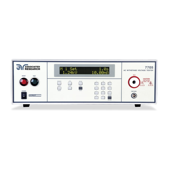
MODEL 7705 (10 kV AC ONLY HIPOT)
MODEL 7710 (12 kV DC ONLY HIPOT)
MODEL 7715 (20 kV AC ONLY HIPOT)
MODEL 7720 (20 kV DC ONLY HIPOT)
SERIAL NUMBER
Ver 1.03
®
© Associated Research, Inc., 2006
13860 West Laurel Drive
Lake Forest, Illinois, 60045-4546
U.S.A.
Printed January 23, 2006
Advertisement
Table of Contents

Subscribe to Our Youtube Channel
Related Manuals for Associated Research HypotMAX 7705


Summary of Contents for Associated Research HypotMAX 7705
- Page 1 MODEL 7710 (12 kV DC ONLY HIPOT) MODEL 7715 (20 kV AC ONLY HIPOT) MODEL 7720 (20 kV DC ONLY HIPOT) SERIAL NUMBER Model © Associated Research, Inc., 2006 13860 West Laurel Drive 7705,10,15,20 Lake Forest, Illinois, 60045-4546 U.S.A. Item 38672 Ver 1.03...
-
Page 3: Table Of Contents
TABLE OF CONTENTS 1. Introduction....................... 1 1.1. Warranty Policies..................1 1.2. Safety Symbols ..................... 2 1.2.1. Product Marking Symbols ..............2 1.2.2. Caution and Warning Symbols ............2 1.3. Glossary of Terms..................3 1.4. Safety ......................4 1.4.1. Service and Maintenance ..............4 1.4.2. - Page 4 3.6. Instrument Controls ..................24 3.6.1. Front Panel Controls................. 24 3.6.2. Rear Panel Controls................26 3.7. Quickstart ....................27 4. System Settings ......................30 4.1. SETUP Key Parameters ................30 4.1.1. PLC Remote..................30 4.1.2. Fail Stop................... 30 4.1.3. LCD Contrast ................... 31 4.1.4.
- Page 5 6.5. Performing a Test..................46 6.5.1. Discharge Function in DC units ............46 6.5.2. Manual Voltage Adjustment ............. 47 7. Displayed Messages ....................48 7.1. Running Test Messages all units ..............48 7.2. Additional Displayed messages for DC units..........50 7.3.
- Page 6 11.3.3. Calibration of 7715 AC Hipot Current ..........75 11.3.4. Calibration of 7710 DC Hipot Current ..........76 11.3.5. Calibration of 7720 DC Hipot Current ..........78 11.3.6. Calibration Complete Message ............79 12. Replacement Parts List ..................80 13. Schematic Index..................... 81 Index is located at the back of the manual.
-
Page 7: Introduction
1. Introduction 1.1. Warranty Policies Associated Research, Inc., certifies that the instrument listed in this manual meets or exceeds published manufacturing specifications. This instrument was calibrated using standards that are traceable to the National Institute of Standards and Technology (NIST). -
Page 8: Safety Symbols
1.2. Safety Symbols 1.2.1. Product Marking Symbols Product will be marked with this symbol when it is necessary to refer to the operation and service manual in order to prevent injury or equipment damage. Product will be marked with this symbol when hazardous voltages may be present. Product will be marked with this symbol at connections that require earth grounding. -
Page 9: Glossary Of Terms
Hipot Tester: Common term for dielectric-withstand test equipment. Hypot®: Registered trademark of Associated Research, Inc., for its dielectric-withstand test equipment. Gas, liquid or solid material which has a volume resistivity of at least 10 12 ohm-cm and is used Insulation: for the purpose of resisting current flow between conductors. -
Page 10: Safety
The instrument, its power cord, test leads, and accessories must be returned at least once a year to an Associated Research authorized service center for calibration and inspection of safety related components. Associated Research will not be held liable for injuries suffered if the instrument is not properly maintained and safety checked annually. -
Page 11: Test Station
1.4.2. Test Station Location Select an area away from the main stream of activity which employees do not walk through in performing their normal duties. If this is not practical because of production line flow, then the area should be roped off and marked for HIGH VOLTAGE TESTING. No employees other than the test operators should be allowed inside. -
Page 12: Test Operator
1.4.3. Test Operator Qualifications This instrument generates voltages and currents that can cause harmful or fatal electric shock and must only be operated by a skilled worker trained in its use. The operator should understand the electrical fundamentals of voltage, current, and resistance. They should recognize that the test instrument is a variable high-voltage power supply with the return circuit directly connected to earth ground, therefore, current from the high-voltage output will flow through any available ground path. -
Page 13: Device Under Test
1.4.5. Device Under Test Never touch the Device Under Test (DUT) or anything connected to it while WARNING high voltage is being applied by the hipot. When testing with DC, always discharge the capacitance of the item under test and anything the high voltage may have contacted–such as test fixtures–before handling it or disconnecting the test leads. -
Page 14: Introduction To Product Safety Testing
1.5. Introduction to Product Safety Testing 1.5.1. The Importance of Safety Testing Product Safety Tests are specified during the design and development stages of a product as well as in the production of the products to insure that it meets basic safety requirements. These tests are designed to verify the safety of the electrical products in that they do not jeopardize the safety of the people, domestic animals, and property of anyone who may come in contact with these products. - Page 15 The equipment used for this test, a dielectric-withstand tester, is often called a “hipot” (for high potential tester). The “rule of thumb” for testing is to subject the product to twice its normal operating voltage, plus 1,000 volts. However, specific products may be tested at much higher voltages than 2X operating voltages + 1,000 volts.
- Page 16 AC testing advantages AC testing is generally much more accepted by safety agencies than DC testing. The main reason for this is that most items being hipot tested will operate on AC voltages. AC hipot testing offers the advantage of stressing the insulation alternately in both polarities, which more closely simulates stresses the product will see in real use.
-
Page 17: Insulation Resistance Test
which will indicate failure almost immediately if the total current reaches the leakage threshold during the initial charging of the product under test. Since a DC hipot does charge the item under test, it becomes necessary to discharge the item after the test. -
Page 18: Run Test
Compliance agency requirements vary on how different products are to be tested. Most specifications call for test currents of between 10 and 30 amps. Test voltages at these currents are typically required to be less than 12 volts. Maximum allowable resistance readings of the safety ground circuit are normally between 100 and 200 milliohms. - Page 19 current. Leakage current measurements are performed on products under normal conditions and single fault conditions as well as reversed polarity. This simulates possible problems, which could occur if the product under test is faulted or misused while the product is operating under high line conditions (110% of the highest input voltage rating of the product).
-
Page 20: Key Features And Benefits
1.7. Key Features and Benefits: HypotMAX The SmartGFI provides maximum operator protection. Patented SmartGFI® If the circuit detects excessive leakage to ground it shuts down the high voltage in less than 1 millisecond. SmartGFI is automatically activated if the DUT is not grounded. - Page 21 Tamper proof front panel This makes it possible to limit user access to the setup screens so that only authorized personnel with a controls security code can change test parameters. The electronic dwell control helps keep test results Electronic dwell settings consistent by ensuring that the test duration is the same for each product tested.
-
Page 22: Getting Started
2. Getting Started Introduction This section contains information for the unpacking, inspection, preparation for use and storage of your Associated Research, Inc., product. 2.1. Unpacking and Inspection 2.1.1. Packaging Your instrument was shipped in a custom foam insulated container that complies with ASTM... -
Page 23: Installation
If you do not have the original packaging materials, please follow these guidelines: • Wrap the instrument in a bubble pack or similar foam. Enclose the same information as above. • Use a strong double-wall container that is made for shipping instrumentation. 350-lb. test material is adequate. -
Page 24: Environmental Conditions
The instrument is shipped with a three-wire power cable. When the cable is connected to an appropriate AC power source, the cable will connect the chassis to earth ground. The type of power cable shipped with each instrument depends on the country of destination. The output power supplies of this instrument are referenced directly to earth CAUTION ground. -
Page 25: Specifications And Controls
3. Specifications and Controls 3.1. 7705 Functional Specifications INPUT 115/230 VAC ± 10%, Single Phase, User selection Voltage 50/60 Hz ± 5% Frequency Fuse 6.3 Amp, 250V Slow Blow DIELECTRIC WITHSTAND TEST MODE Output Rating 10 kV @ 20 mA Output Adjustment Range: 0.00 –... -
Page 26: 7710 Functional Specifications
3.2. 7710 Functional Specifications INPUT 115/230 VAC ± 10%, Single Phase, User selection Voltage 50/60 Hz ± 5% Frequency Fuse 6.3 Amp, 250V Slow Blow DIELECTRIC WITHSTAND TEST MODE Output Rating 12 kV @ 10 mA Output Adjustment Range: 0.00 – 12.00 kV DC Resolution: 10 volt/step ±... -
Page 27: 7715 Functional Specifications
Ramp-UP Range: 0.4 – 999.9 sec Ramp-DOWN Range: 0.0, 1.0 – 999.9 sec (0=OFF) Resolution: 0.1 sec increments ± (0.1% + 1 count) Accuracy: Ground Fault GFI Trip Current: 1 mA max Interrupt HV Shut Down < 1 ms (Actual Output Voltage discharge time is response: not included and vary due to load condition) 3.3. -
Page 28: 7720 Functional Specifications
Ramp-UP Range: 0.3 – 999.9 sec Ramp-DOWN Range: 0.0 – 999.9 sec Resolution: 0.1 sec increments ± (0.1% + 1 count) Accuracy: Ground Fault GFI Trip Current: 1 mA max Interrupt HV Shut Down response: < 1 ms 3.4. 7720 Functional Specifications INPUT 115/230 VAC ±... -
Page 29: General Specifications
Maximum Capacitive 1.5 uF < 2 kV 0.12 uF < 14 kV Load 0.28 uF < 4 kV 0.10 uF < 16 kV 0.18 uF < 6 kV 0.08 uF < 20 kV 0.15 uF < 10 kV No load ≤ 300 ms. Capacitive loading will increase the discharge Discharge time time. -
Page 30: Instrument Controls
3.6. Instrument Controls 3.6.1. Front Panel Controls 77XX ASSOCIATED AC WITHSTAND VOLTAGE TESTER RESEARCH, INC. 1. LCD DISPLAY: The 2x20-character display indicates test function, memory location, test parameter and failure type as well as test measurements during a test. 2. POWER SWITCH: Rocker style power switch with international ON ( | ) and OFF (0) markings. - Page 31 77XX ASSOCIATED AC WITHSTAND VOLTAGE TESTER RESEARCH, INC. 7. UP-DOWN ARROW KEYS: Use these keys to enter and move through the function parameter menu for test parameter setup. 8. SETUP: Use this key to enter the setup menu and view or change the display contrast, alarm volume, and PLC remote settings.
-
Page 32: Rear Panel Controls
3.6.2. Rear Panel Controls 1. CHASSIS GROUND (EARTH) TERMINAL: This terminal should be connected to a good earth ground before operation. 2. CALIBRATION BUTTON: To put the instrument into the calibration mode, push this button and turn on the power switch simultaneously. 3. -
Page 33: Quickstart
3.7. Quickstart This quick start guide assumes the operator has some familiarity with automated Electrical Safety testing. Locate a suitable testing area and be sure you have read all safety instructions WARNING for the operation of the instrument and suggestions on the test area set-up in the Safety section. - Page 34 of this tester but they are not intended to be held by the operator during the test while the high voltage is energized. Please insure that you do not make contact with the alligator clip or the clip insulator while high voltage is energized. Remote Interlock HypotMAX is equipped with a featured referred to as “Remote Interlock”.
- Page 35 ENTER key. The results of the last test in the process will be followed by the first test when scrolling through the results. All buffers are cleared at the start of the next test cycle. Pressing the EXIT key will return you to the Settings screen.
-
Page 36: System Settings
4. System Settings 4.1. SETUP Key Parameters At the Setting, Pass, or Fail screen press the SETUP key. Use the SETUP key to progress through the menu of System Parameters. Successive key presses will advance the menu forward. The sequential forward menu items are: PLC Remote, Fail Stop, Contrast, Alarm, Smart GFI, GPIB address, BUS Remote Command Set, Memory Lock. -
Page 37: Lcd Contrast
If the Fail stop is off and a failure occurs during the test sequence, the RESET button will light and a short alarm will sound but the sequence will continue to the end. At the end of the test sequence, the RESET button will light and alarm will sound indicating failure during the sequence. -
Page 38: Smart Gfi
Use the Numeric keys to enter the Audible Alarm level, then press the ENTER key. The program will provide a sample sound for checking immediately when the ENTER key is pressed. Change the Volume again or press the SETUP key to forward to the Smart GFI selection. Press the EXIT key to return to the operation mode. -
Page 39: Gpib Address
4.1.6. GPIB Address Only appears if the GPIB option 01 is installed Press the SETUP key to advance the menu to the GPIB address parameter. The display will show: GPIB addr Range: 0-31 Use the Numeric keys to enter the GPIB Address, then press the ENTER key. Change the GPIB address again or press the SETUP key to advance to the Memory Lock parameter. -
Page 40: Lock/Local Key
Toggle the Memory Lock function or press the SETUP key to forward to the PLC Remote selection. Press the EXIT key to return to the operation mode. The program will store the Memory Lock setting automatically. 4.2. LOCK/LOCAL Key 4.2.1. Lock Function Press the LOCK/LOCAL key. -
Page 41: Password Setting
4.3. Password Setting Press the “4” and “7” keys simultaneously and then turn the input power switch on. The program will automatically enter to the Password Setting mode and the display screen will show: Password Password X X X X Range : 0 - 9 9 9 9 Range : 0 - 9 9 9 9 The Password can be any four (4) digit number. -
Page 42: Test Parameters Setup Procedures
5. Test Parameters Setup Procedures 5.1. Test Parameters Description of Test Parameters Voltage: The Voltage that is applied to the High Voltage and Return terminals or the Current and Return terminals during a test. HI-Limit: A maximum current or resistance threshold that when exceeded triggers a failure. LO-Limit: A minimum current or resistance threshold that when not exceeded triggers a failure. -
Page 43: Setting Up Tests
5.2. Setting Up Tests Before going to setup the Test Parameters, make sure that the Keyboard is in the Unlock mode, and then follow this procedure to setup the Test Parameters. Press the Memory key and using the numeric keypad enter the Memory number you would like to edit and then press the ENTER key. -
Page 44: Lo-Limit Current Setting
Press the EXIT key to exit from the setting mode to the operation mode if all parameters have been set. 5.2.3. LO-Limit Current setting Advance the menu to the LO-Limit parameter. The display will show: LO-Limit = XXX.X µA LO-Limit = X.XXX mA Range: 0.000 –... -
Page 45: Dwell Time Setting
5.2.6. Dwell Time setting Advance the menu to the Dwell Time parameter. The display will show: Dwell Time = XXX.X s Dwell Time = XXX.X m Range : 0.3 - 999.9s 0 = Const. Range : 0.4 - 999.9m 0 =Const. Use the Numeric keys to enter the Dwell Time setting, and then press the ENTER key. -
Page 46: Arc Detect And Arc Sensitivity Selection
5.2.9. Arc Detect and Arc Sensitivity Selection Advance the menu to the Arc Detection selection. The display will show: Arc Detect = Arc Detect = O F F <ENTER> to Select <ENTER> to Select Use the ENTER key to toggle the Arc Detect mode, then press the ∧ or ∨ key to advance the program to the Arc Sense parameter or press the EXIT key to exit from the setting mode to the operation mode. -
Page 47: Charge-Lo Setting (Dc Units Only)
5.2.11. Charge-LO setting (DC units only) Advance the menu to the Charge-LO parameter. The display will show: Charge-LO = XXX.X µA <TEST> to Auto Set The Charge-LO function is used to check if the test cables are connected properly at the beginning of a test. -
Page 48: Reviewing Test Results
Use the ENTER key to toggle the Connect Mode ON and OFF. This function when turned ON will connect or link the current memory to the next memory. This Allows HypotMAX to Run 50 consecutive tests in a sequence if desired. 5.3. -
Page 49: Memory And Default System Parameter Initialization
5.5. Memory and Default System Parameter Initialization Warning Initializing the instrument will overwrite all memories with the ACW Default parameters! Press the “0” and the “1” keys and power the instrument at the same time. A question will appear on the display as follows: Defaults? SETUP=Yes EXIT=No Pressing the SETUP key will load the Default Test and System parameters. -
Page 50: Operating Instructions
6. Operating Instructions 6.1. Preparation and Instrument Connections Before the operation of this instrument, make sure that all Test Parameters have been set properly according to the Test Parameters Setup Procedures. Also, check the system setting of Remote Control, LCD Contrast, the Alarm Volume, and Fail Stop. Be sure to connect the appropriate test leads to the device under test (DUT) or test fixture. -
Page 51: Settings Screen
6.3. Settings Screen The settings screen will show parameter settings of the test that will be performed and the memory location that they are stored in. This screen can be accessed after a test is Aborted or Passed by pressing the RESET button or after a test failure by pressing the RESET button twice. -
Page 52: Performing A Test
6.5. Performing a Test 1. From the Settings screen, press the MEMORY key and select the memory you wish to perform using the numeric keypad then press the ENTER key to return you to the Perform Test screen. 2. Attach the appropriate load or DUT to the instrument (refer to section 6.1 for instrument connections). -
Page 53: Manual Voltage Adjustment
The voltage and time of the discharging DUT will be displayed during the discharge period but this information is only intended for reference and cannot be reviewed after the end of the discharge period. The process signal of the remote I/O remains active during the discharge period and the high voltage lightning bolt indicator on the front panel of the instrument is also active during the discharge period. -
Page 54: Displayed Messages
7. Displayed Messages 7.1. Running Test Messages all units If the test in process is Aborted with the RESET button or remote control, the display will show: MXX Abort XXX.X s XX.XX KV XX.XX mA If the test in process is Aborted with the RESET button or remote control before the meter readings are taken, the display will show: MXX Abort XXX.X s... - Page 55 If the DUT current exceeds the HI-Limit of AC Withstand Voltage test and the leakage current is not within the metering range, the display will show: MXX HI-Limit XXX.X s > 10 mA XX.XX KV If the DUT current is well beyond the metering range of AC Withstand Voltage test the instrument assumes that the failure is due to a short circuit, the display will show: MXX Short XXX.X s...
-
Page 56: Additional Displayed Messages For Dc Units
7.2. Additional Displayed messages for DC units If the Ramp-HI function is enabled and the leakage current during the Ramp cycle exceeds 9.999mA for the model 7710 or 5mA for the model 7720, then the display will show: MXX Ramp-HI XXX.X s MXX Ramp-HI XXX.X s... -
Page 57: Bus Remote Message
“Fatal Error” mode and requires that the instrument be serviced by Associated Research. The customer should contact Associated Research, Inc to receive further instruction. An example of the Fatal Error screen appears as... -
Page 58: Remote Control
8. Remote Control Two 9-pin “D” type connectors are mounted on the rear panel that provide REMOTE-INPUT- OUTPUT control and information. These connectors mate with standard 9 pin D-sub- miniature connector provided by the user. The output mates to a male (plug) connector while the input mates to a female (receptacle) connector. - Page 59 The following describes how the relays operate for each test condition: PROCESSING – The relay contact closes the connection between pin (5) and pin (6) while the instrument is performing a test. The connection is opened at the end of the test. The process contact is closed all the way through to the end of the discharge cycle in DC units.
- Page 60 DO NOT CONNECT VOLTAGE OR CURRENT TO THE SIGNAL CAUTION INPUTS, THIS COULD RESULT IN DAMAGE TO THE CONTROL CIRCUITRY. MEMORY ONE – Momentarily connecting terminal 7 to 8 signals the instrument to immediately begin the test program that is stored in memory one. MEMORY TWO –...
-
Page 61: Bus Remote Interface Gpib / Rs-232
9. Bus Remote Interface GPIB / RS-232 This section provides information on the proper use and configuration of bus remote interface. The RS-232 remote interface is standard on model 77XX but the GPIB (IEEE-488) interface option can be substituted for the RS-232 interface. Please refer to the Option section of this manual for details on the HypotMAX options. -
Page 62: Gpib Connector
Data Lines: The eight data lines, DI01 through DI08 carry data and command messages. The 7-bit ASCII or ISO code set is used and the eighth bit DI08 is unused. Handshake Lines: The transfer of message bytes between devices is done via three asynchronous control lines. -
Page 63: Gpib Address
A maximum separation of 4 m between any two devices and an average separation of 2 m over the entire bus. A maximum total cable length of 20 m. No more than 15 device loads connected to each bus, with no less than two-thirds powered on. For example 1 GPIB controller and a maximum of 14 GPIB instruments. -
Page 64: Rs-232 Interface
9.8. RS-232 Interface This interface is standard on HypotMAX. This interface provides all of the control commands and parameter setting commands of the GPIB interface with the exception of some of the 488.2 Common Commands and SRQ capability. All commands can be found in the command list, section 9.9.1 to 9.9.6 of this manual. -
Page 65: Test Execution Commands
When sending the command none of the previous mentioned characters should be included, they are only for reference purposes in this manual. Nor should quotation (“ ”) marks be include when sending the commands. Also the command and the parameter data must be separated with a space. - Page 66 ADD <test,p1,p2,p3…> This command edits all parameters in a memory location. Parameters will be edited at the memory location that has been selected. The parameter <test> indicates the test type. The test type values ACW or DCW must be used. The parameters <p1,p2> etc. indicate the individual settings for each test. All parameters must be included with the command and should appear in the same order that is shown in the table below.
-
Page 67: Test Parameter Editing Commands And Companion Queries
9.9.3. Test Parameter Editing Commands and Companion Queries These commands are used to modify the test parameter within each memory. These commands require a parameter value to be included with the command. The companion query command will read the parameter. The writing of the parameter requires that the unit not be included with the value, only the numeric value should be included with the command. -
Page 68: System Parameter Editing Commands And Companion Queries
9.9.4. System Parameter Editing Commands and Companion Queries These commands are used to modify the system parameters for the instrument. These commands require a parameter value to be included with the command. The companion query command will read the parameter using the same value that is used for setting the parameter. Command Name Value... -
Page 69: Query Commands
9.9.5. Query Commands These query commands will retrieve data from the instrument. The GPIB bus application requires an IEEE-488 read command to be sent after the query command. These commands include functions for retrieving test data, test results and remote hardware status as well as setup file information. -
Page 70: Ieee 488.2 Common Commands
*ESR?, *ESE, *ESE? and *STB? Command Name Description *IDN? Identification Query Associated Research Inc., Model Number, Serial Number, Firmware Revision *RST Reset Command Resets HypotMAX *TST? - Page 71 *IDN? Read the instrument identification string. Company =Associated Research Inc. *RST Reset the instrument to original power on configuration. Does not clear Enable register for Standard Summary Status or Standard Event Registers. Does not clear the output queue. Does not clear the power-on-status-clear flag.
-
Page 72: Status Reporting
*ESE? Queries the Standard Event enable register. Returns the decimal value of the binary-weighted sum of bits. *STB? Read the Status Byte. Returns the decimal value of the binary-weighted sum of bits. *SRE <value> Service Request enable register controls which bits from the Status Byte should be use to generate a service request when the bit value = 1. -
Page 73: Gpib Service Request
Standard Event Register Status Byte Register Bit Binary Event Register Enable Summary Register Enable weight Register Register Operation Complete ALL PASS not used FAIL Query Error ABORT Device Error TEST IN PROCESS Execution Error Message Available (MAV) Command Error Event Summary Bit (ESB) not used Request Service (RQS) or not used... -
Page 74: Non Volatile Memory
If you wish to set the Ramp-UP time of the test across the IEEE bus at 10 seconds, do the following, send the string "ERU 10.00". This tells the instrument to set the Ramp-UP time at 10.00 seconds. To read the live testing data, first send the string "TD?" then send the GPIB command to read. -
Page 75: Options
10. Options Introduction This section contains a list and descriptions of available factory installed options at the time of this printing. The list of options contains an option code number that can be referenced on the data plate on the rear panel of the unit. Option Label On the rear panel of the instrument, you will find a label that contains the option code. - Page 76 Auto Print Please press the SETUP key to enter the Setup menu. Press the SETUP key six more times to scroll to the Auto Print selection the screen will show: AUTO Pr int = ON AUTO Pr int = OFF <ENTER>...
- Page 77 Form Feed Please press the SETUP key. The Form Feed screen appears as follows: For m Feed = ON Pr int Mode = OFF <ENTER> to Select <ENTER> to Select This command forces a form feed after each complete test sequence. When the form feed is turned off the pages will break whenever the page is determined to be full by the printer.
-
Page 78: Calibration Procedure
Inc. for its annual calibration. In order to be eligible for the extended warranty instruments must be purchased and used in North America and returned to Associated Research, Inc. for calibration service at least once every twelve months. A 3-Year warranty is also available for instruments purchased and used in North America. -
Page 79: Calibration Initialization
11.2. Calibration Initialization Press and hold the calibration key on the rear panel with a pen, pencil, or small screwdriver while powering ON the HypotMAX. The HypotMAX enters calibration mode after the power on sequence is complete. The program will automatically enter to the calibration mode and the display screen will show: Calibration Mode ∨... - Page 80 Connect a resistor about 100KΩ/40W in series with a AC standard Ammeter which can measure up to 20.00mA to the output leads. The Ammeter should be connected to the return lead, then press the TEST button, the program will automatically generate an output of about 2000V/20mA and the display will show: Current = Enter Standard I-out...
-
Page 81: Calibration Of 7715 Ac Hipot Current
11.3.3. Calibration of 7715 AC Hipot Current AC Hipot, 10mA current range Press the ∨ key, the program will advance to the AC 10.00mA range calibration of the hipot test. The display will show: AC 10.00mA, 100KΩ <T E S T> t o C a l i b r a t e Connect a resistor about 100KΩ/10W in series with a AC standard Ammeter which can measure up to 10.00mA to the output leads. -
Page 82: Calibration Of 7710 Dc Hipot Current
Use the Numeric keys to enter the standard value of current, unit mA, and then press the ENTER key to store the standard value of AC 3.500mA range of the hipot test and the display will show: AC 3.500mA, 100KΩ <T E S T>... - Page 83 Connect a resistor about 100KΩ/10W in series with a DC standard Ammeter which can measure up to 3000µA to the output leads. The Ammeter should be connected to the return lead, then press the TEST button, the program will automatically generate an output of about 300V/3000µA and the display will show: µA Current =...
-
Page 84: Calibration Of 7720 Dc Hipot Current
11.3.5. Calibration of 7720 DC Hipot Current DC Hipot, 5.00mA current range Press the ∨ key, the program will advance to the DC 5.00mA range calibration of the hipot test. The display will show: DC 5.00mA, 100KΩ <T E S T> t o C a l i b r a t e Connect a resistor about 100KΩ/2.5W in series with a DC standard Ammeter which can measure up to 5.00mA to the output leads. -
Page 85: Calibration Complete Message
Use the Numeric keys to enter the standard value of current, unit µA, and then press the ENTER key to store the standard value of DC 3500µA range of hipot test and the display will show: DC 3500µA, 100KΩ <T E S T> t o C a l i b r a t e DC Hipot, 350µA current range Press the ∨... -
Page 86: Replacement Parts List
12. Replacement Parts List Rev: B 1/23/2006 ECO: 5162 Part Number Qty. Ref. Designator Description Supplied Accessories 37801 3U Rack Mount Handle 37800 3U Rack Mount Bracket 38549 Screws Handle to Bracket 37780 Fuse 6.3A 250V Slow Blow 20mm 38686 (7715 and 7720 only) High Voltage Cable 38694... -
Page 87: Schematic Index
13. Schematic Index Drawing Description Model Reference Pages Number Designator S07705 Wiring Diagram 7705 7705 S07710 Wiring Diagram 7710 7710 S07715 Wiring Diagram 7715 7715 S07720 Wiring Diagram 7720 7720 S38665 Main Control Board CON 4320 S38666 HV Control Board HV 4320 S38703 High Voltage Board AC... - Page 88 Index AC Withstand................... 27, 37, 45, 47, 48, 49 Arc .................14, 19, 20, 21, 22, 36, 37, 40, 42, 48, 59, 60 Benefits..........................14 Breakdown........................3, 48 Calibration Procedure....................34, 71, 72 Charge-LO ........................36, 58 Connected Memories..................28, 31, 42, 46, 72 Connected Steps......................58, 59, 62 Continuity Test........................
- Page 89 Memory ..15, 23, 24, 26, 27, 28, 30, 33, 34, 36, 37, 42, 43, 44, 45, 46, 52, 53, 56, 58, 64, 67 Menu..........12, 14, 25, 30, 31, 32, 33, 34, 36, 37, 38, 39, 40, 41, 46, 72 Min-Lmt..........................
Need help?
Do you have a question about the HypotMAX 7705 and is the answer not in the manual?
Questions and answers
i have the 7720 hypot, my item came back from cal on lock condition why cant i set my test parameters?
You can't set test parameters on the HypotMAX 7705 after calibration if it is in a lock condition because parameter adjustments are restricted to a special calibration mode. This mode is protected to prevent unauthorized changes, and access is likely limited or locked after calibration to maintain accuracy and compliance.
This answer is automatically generated