Table of Contents
Advertisement
Advertisement
Table of Contents

Related Manuals for Hitachi F700


Summary of Contents for Hitachi F700
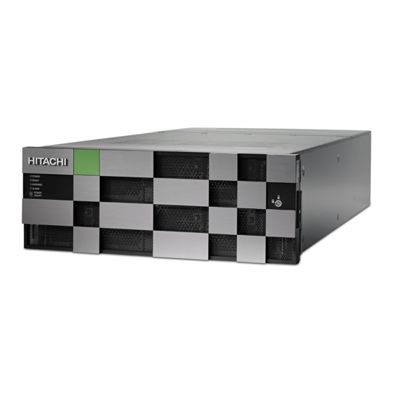
- Page 1 Hitachi Virtual Storage Platform F700 88-02-0x Hardware Reference Guide This document provides information about the system hardware components and the mechanical and environmental specifications for the Hitachi Virtual Storage Platform F700 all-flash array. MK-97HM85017-01 September 2018...
- Page 2 Materials. “Materials” mean text, data, photographs, graphics, audio, video and documents. Hitachi reserves the right to make changes to this Material at any time without notice and assumes no responsibility for its use. The Materials contain the most current information available at the time of publication.
-
Page 3: Table Of Contents
16-Gbps Fibre Channel (2-port) board LEDs and connectors....24 Back-end module LEDs and connectors............25 Chapter 3: Drive trays................27 Small form-factor drive tray (DBS)..............27 SFF with front panel bezel................27 SFF front panel without bezel...............28 Contents Hitachi Virtual Storage Platform F700 Hardware Reference Guide... - Page 4 Physical service processor connections............65 Appendix D: Data and power cables........... 67 Required cables....................67 Fibre Channel cables..................69 iSCSI cables...................... 72 iSCSI standards....................75 iSCSI specifications..................75 Managing cables....................78 AC power cables....................81 Power cable assemblies................81 AC connections.................... 83 Contents Hitachi Virtual Storage Platform F700 Hardware Reference Guide...
- Page 5 Power cable usage guidelines..............85 Three-phase power considerations for racks..........85 Cable management..................85 Appendix E: Power distribution units for Hitachi Universal V2 Rack .......................86 Americas single-phase PDU 1P30A-8C13-3C19UL.P........86 Americas single-phase PDU 1P30A-15C13-3C19UL.P........87 Americas three-phase PDU 3P30A-8C13-3C19UL.P........87 Americas three-phase PDU 3P30A-15C13-3C19UL.P........88 Americas three-phase PDU 3P30A-24C13-6C19UL.P........89...
-
Page 6: Preface
Preface This guide describes the hardware features and specifications of the Hitachi Virtual Storage Platform F700. Intended audience This document is intended for Hitachi Vantara representatives, system administrators, and authorized service providers who install, configure, and operate the VSP Fx00 models . -
Page 7: Product Version
ARISING IN ANY WAY OUT OF THE USE OF THIS SOFTWARE, EVEN IF ADVISED OF THE POSSIBILITY OF SUCH DAMAGE. Product version This document revision applies to VSP F700 firmware 88-02-0x or later. Release notes Read the release notes before installing and using this product. They may contain requirements or restrictions that are not fully described in this document or updates or corrections to this document. - Page 8 Indicates required or expected values. Example: { a | b } indicates that you must choose either a or b. | vertical bar Indicates that you have a choice between two or more options or arguments. Examples: Preface Hitachi Virtual Storage Platform F700 Hardware Reference Guide...
-
Page 9: Conventions For Storage Capacity Values
1,000 TB or 1,000 bytes 1 exabyte (EB) 1,000 PB or 1,000 bytes Logical capacity values (for example, logical device capacity, cache memory capacity) are calculated based on the following values: Preface Hitachi Virtual Storage Platform F700 Hardware Reference Guide... -
Page 10: Accessing Product Documentation
Getting help Hitachi Vantara Support Connect is the destination for technical support of products and solutions sold by Hitachi Vantara. To contact technical support, log on to Hitachi Vantara Support Connect for contact information: https://support.hitachivantara.com/en_us/ contact-us.html. Hitachi Vantara Community is a global online community for Hitachi Vantara customers, partners, independent software vendors, employees, and prospects. -
Page 11: Comments
Please send us your comments on this document to doc.comments@hitachivantara.com. Include the document title and number, including the revision level (for example, -07), and refer to specific sections and paragraphs whenever possible. All comments become the property of Hitachi Vantara Corporation. Thank you! Preface... -
Page 12: Chapter 1: Overview
Chapter 1: Overview The Hitachi Virtual Storage Platform F700 is a versatile modular, rack-mountable all-flash array storage system equipped with drive boxes, supporting flash module drives, scaled for various storage capacity configurations. To deliver consistent low latency host response times and highest IOP performance across all host connection ports, conventional hard-disk drives are not supported in an all-flash configuration. - Page 13 Flash drive tray (DBF): Up to 12 flash module drives (FMD) can be installed (2U size) ■ Supports system environments with mixed operating systems such as UNIX, Linux, ■ Windows, and VMware Chapter 1: Overview Hitachi Virtual Storage Platform F700 Hardware Reference Guide...
-
Page 14: Chapter 2: System Controller
Each controller includes the following internal components such as a processor, dual in- line cache memory modules (DIMMs), cache flash memory (CFM), battery, and fans. The controller has an Ethernet connection for out-of-band management using Hitachi Device Manager - Storage Navigator. If the data path through one controller fails, all drives remain available to data hosts using a redundant data path through the other controller. - Page 15 ALARM LED Off: Normal operation. Red: Processor failure (system might be down). For assistance, contact customer support: https:// support.hitachivantara.com /en_us/contact-us.html. POWER ON/OFF (main Powers the storage system. switch) Chapter 2: System controller Hitachi Virtual Storage Platform F700 Hardware Reference Guide...
-
Page 16: Cbl Controller Front Panel Leds (Without Bezel)
(SIM) are issued: 452xxx, 462xxx, 3077xx, 4100xx, and 410100. Controllers Controller 1 (bottom) and Controller 2 (top). Backup module Chapter 2: System controller Hitachi Virtual Storage Platform F700 Hardware Reference Guide... - Page 17 Blink red one time: Main battery failure. Blink red two times: Backup battery failure. Blink red three times: Both batteries failed or preventive maintenance replacement of batteries can run. Chapter 2: System controller Hitachi Virtual Storage Platform F700 Hardware Reference Guide...
-
Page 18: Cbl Controller Rear Panel Leds
Back end module LAN blade CBL controller power supply unit LEDs and connectors The following table lists the definitions of the CBL controller power supply unit LEDs and connectors. Chapter 2: System controller Hitachi Virtual Storage Platform F700 Hardware Reference Guide... -
Page 19: Host, Network, And Drive Tray Ports And Leds
Front end modules The following front end modules are available for the controllers. The LEDs display the operating status of the module. Chapter 2: System controller Hitachi Virtual Storage Platform F700 Hardware Reference Guide... -
Page 20: 10-Gbps Iscsi Board Leds And Connectors (Optical)
Blue: Normal link status. Blink blue: Front end module is in communication status. ISCSI connectors Connect to Ethernet cables. 10-Gbps iSCSI board LEDs and connectors (copper) Chapter 2: System controller Hitachi Virtual Storage Platform F700 Hardware Reference Guide... - Page 21 Off: No link connection. PORT LED Green: Link connection is established. Blinking: Communication is in progress. Off: No link connection or not ready to communicate. ISCSI connectors Connect to Ethernet cables. Chapter 2: System controller Hitachi Virtual Storage Platform F700 Hardware Reference Guide...
-
Page 22: 8-Gbps, 16-Gbps, Or 32-Gbps Fibre Channel (4-Port) Board Leds And Connectors
Item Description Fibre Channel connectors Connect to Fibre Channel cables. STATUS LED Green: Front end module is in power-on state. Red: Front end module can be removed safely. Chapter 2: System controller Hitachi Virtual Storage Platform F700 Hardware Reference Guide... - Page 23 8-Gbps, 16-Gbps, or 32-Gbps Fibre Channel ports (left to right) CHB number Port 1 Port 2 Port 3 Port 4 CHB-1A CHB-1B CHB-1C CHB-1D CHB-1E CHB-1F CHB-1G CHB-1H CHB-2A CHB-2B CHB-2C CHB-2D CHB-2E CHB-2F CHB-2G Chapter 2: System controller Hitachi Virtual Storage Platform F700 Hardware Reference Guide...
-
Page 24: 16-Gbps Fibre Channel (2-Port) Board Leds And Connectors
Red: Small form-factor pluggable can be removed. Blue: Normal link status at 16-Gbps. Green: Normal link status at 4-Gbps or 8-Gbps. Fibre Channel connectors Connect to Fibre Channel cables. Chapter 2: System controller Hitachi Virtual Storage Platform F700 Hardware Reference Guide... -
Page 25: Back-End Module Leds And Connectors
CHB-1E CHB-1F CHB-1G CHB-1H CHB-2A CHB-2B CHB-2C CHB-2D CHB-2E CHB-2F CHB-2G CHB-2H Back-end module LEDs and connectors The back-end module LEDs display the operating status of the module. Chapter 2: System controller Hitachi Virtual Storage Platform F700 Hardware Reference Guide... - Page 26 Red: Back end module can be removed safely. PORT LED Blue: Link status is normal. PATH 0 connector Connect to a drive tray. PATH 1 connector Connects to a drive tray. Chapter 2: System controller Hitachi Virtual Storage Platform F700 Hardware Reference Guide...
-
Page 27: Chapter 3: Drive Trays
2U (88.2 mm) 2.5 inch (SFF) SFF with front panel bezel Number Item Description POWER LED Green: Drive tray is powered on. READY LED Green: Drive tray is operational. Chapter 3: Drive trays Hitachi Virtual Storage Platform F700 Hardware Reference Guide... -
Page 28: Sff Front Panel Without Bezel
Can be turned on or ■ turned off by the maintenance utility. ALM LED Red: Drive stopped due to a failure and can be replaced. ACT LED Green: Normal operation. Chapter 3: Drive trays Hitachi Virtual Storage Platform F700 Hardware Reference Guide... -
Page 29: Sff Rear Panel
ALARM LED Red: ENC can be replaced. PATH (IN) LED Blue: IN side port is linked PATH (IN) connector Connects to a controller or drive tray. Chapter 3: Drive trays Hitachi Virtual Storage Platform F700 Hardware Reference Guide... -
Page 30: Ac Power Supply Unit Leds And Connectors
LEDs to display its operating status. Number Item Description RDY LED Green: Normal operation. ACI IN LED Green: AC input is operating normally. ALM LED Red: Power supply unit can be replaced. Chapter 3: Drive trays Hitachi Virtual Storage Platform F700 Hardware Reference Guide... -
Page 31: Flash Module Drive Tray (Dbf)
■ the chassis. Can be turned on or ■ turned off by the maintenance utility. Lock Locks and unlocks the front panel bezel by using the supplied key. Chapter 3: Drive trays Hitachi Virtual Storage Platform F700 Hardware Reference Guide... -
Page 32: Fmd Front Panel Without Bezel
Note: ACT indicator is only printed on some types of FMDs. POWER, READY, and Green: Drive tray is LOCATE LEDs powered on. Green: Drive tray is operational. Chapter 3: Drive trays Hitachi Virtual Storage Platform F700 Hardware Reference Guide... -
Page 33: Fmd Rear Panel
Green: ENC is in the power- on state. Locate LED Amber: Indicates the location of ■ the chassis. Can be turned on or ■ turned off by the maintenance utility. Chapter 3: Drive trays Hitachi Virtual Storage Platform F700 Hardware Reference Guide... - Page 34 Green: Power supply unit is operating normally. RDY LED Green: Power supply unit is AC IN LED operating normally. ALM REPLACE LED Red: Power supply unit can be replaced. Chapter 3: Drive trays Hitachi Virtual Storage Platform F700 Hardware Reference Guide...
-
Page 35: Chapter 4: Service Processor
The SVP is also available as a 64-bit software application provided by Hitachi Vantara. For the latest interoperability updates and details, see the SVP (Service Processor) OS and Hypervisor support for Gx00, Fx00 report at https://support.hitachivantara.com/en_us/... -
Page 36: Service Processor Description
<model number><system serial number>/emergency.do. For example: Storage system model Storage system serial number number 8320004 456789 http://192.168.0.15/dev/ storage/8320004456789/ emergency.do 8340004 456789 http://192.168.0.15/dev/ storage/8340004456789/ emergency.do 8360004 456789 http://192.168.0.15/dev/ storage/8360004456789/ emergency.do Chapter 4: Service processor Hitachi Virtual Storage Platform F700 Hardware Reference Guide... -
Page 37: Svp Front Panel
Turning on automatic Windows updates or using the manual Windows update ■ method. Installing antivirus software that has been tested and approved by Hitachi. ■ SVP front panel The front panel of the physical SVP with Windows 10 Enterprise operating system is equipped with LEDs, a reset button, and a power button. - Page 38 Note: After the Initial Startup Wizard is complete, the SVP can be used in non- bridge mode. In this mode, the cables can be removed from SVP ports LAN3 and LAN4 and attached to switches. For more information, contact customer support. Chapter 4: Service processor Hitachi Virtual Storage Platform F700 Hardware Reference Guide...
-
Page 39: Chapter 5: Maintaining The Storage System
To avoid this situation, charge the battery for more than three hours at least once every six months. Chapter 5: Maintaining the storage system Hitachi Virtual Storage Platform F700 Hardware Reference Guide... -
Page 40: Battery Unit
Up to 24 degrees Celsius 5 years Up to 30 degrees Celsius 5 years Up to 34 degrees Celsius 4 years Up to 40 degrees Celsius 3 years Chapter 5: Maintaining the storage system Hitachi Virtual Storage Platform F700 Hardware Reference Guide... -
Page 41: Appendix A: Storage System Parts List
Appendix A: Storage system parts list The following parts list describes the standard and optional hardware components for the storage systems. For more information about the storage system, contact an Hitachi Vantara sales representative. VSP F700 parts list The VSP F700 includes the following standard and optional components. - Page 42 SFP for 32 Gbps Longwave 0-48 DW-F800-BAT Battery Note: 1. A DIMM of a particular capacity cannot be mixed with different capacities in a storage system configuration. Appendix A: Storage system parts list Hitachi Virtual Storage Platform F700 Hardware Reference Guide...
- Page 43 Table 9 DBS drive tray components Model number Part description Quantity DW-F800-DBSC 2U chassis AC Power supply unit Front bezel (2U) DW-F800-RRDB Rail kit Appendix A: Storage system parts list Hitachi Virtual Storage Platform F700 Hardware Reference Guide...
-
Page 44: Drive Tray And Drive Configuration
Drive trays Maximum drive drive (FMD) Data and power cable model list The following tables list the data and power cables available to the storage system. Appendix A: Storage system parts list Hitachi Virtual Storage Platform F700 Hardware Reference Guide... - Page 45 5 m SAS cable, including omega clips (2) DW-F800-SCQ10A 10 m SAS optical cable DW-F800-SCQ30A 30 m SAS optical cable DW-F800-SCQ1HA 100 m SAS optical cable Appendix A: Storage system parts list Hitachi Virtual Storage Platform F700 Hardware Reference Guide...
- Page 46 30 m LC-LC optical cable for optical A-6515-JM50L 50 m LC-LC optical cable for optical A-6515-JM100L 100 m LC-LC optical cable for optical A-6515-JM200L 200 m LC-LC optical cable for optical Appendix A: Storage system parts list Hitachi Virtual Storage Platform F700 Hardware Reference Guide...
- Page 47 Data and power cable model list Model number Specification A-6515-JM300L 300 m LC-LC optical cable for optical Appendix A: Storage system parts list Hitachi Virtual Storage Platform F700 Hardware Reference Guide...
-
Page 48: Appendix B: System Specifications
Appendix B: System specifications The mechanical, electrical, and environmental specifications of the storage system are listed. VSP F700 mechanical specifications The following tables list the system specifications for VSP F700. CBL controller chassis Item Specification Physical dimension 483 × 808.1 × 174.3 mm... - Page 49 2. Can be mounted on the RKU rack. For the mounting, special rails for the rack and decoration panels are required separately depending on the number of the mounted storage systems. 3. The value is at maximum level. Appendix B: System specifications Hitachi Virtual Storage Platform F700 Hardware Reference Guide...
- Page 50 1000 Mbps (iSCSI - Optical) 1000 Mbps (iSCSI - Copper) Number of ports 16/32 Gbps FC (Optical): 64 10 Gbps iSCSI (Optical): 32 10 Gbps iSCSI (Copper): 32 Transferred block size Appendix B: System specifications Hitachi Virtual Storage Platform F700 Hardware Reference Guide...
- Page 51 However, there is still a possibility of losing data caused by unforeseeable hardware or software failure. Users should always follow recommended best practices and back up all data. Appendix B: System specifications Hitachi Virtual Storage Platform F700 Hardware Reference Guide...
-
Page 52: Electrical Specifications
AC 1,500 V (100mA, 1min) Insulation resistance DC 500 V, 10 MΩ or more Electrical specifications The electrical input power specifications for the storage systems are described in the following table. Appendix B: System specifications Hitachi Virtual Storage Platform F700 Hardware Reference Guide... -
Page 53: Environmental Specifications
Caution: The following storage system components are not supported in high-temperature environments. Do not operate the following components at temperatures of 40°C or higher: Hitachi Vantara-provided service processor (SVP) server ■ First-generation FMDs (non-DC2 FMDs) ■ Appendix B: System specifications Hitachi Virtual Storage Platform F700 Hardware Reference Guide... - Page 54 (m/s 9.8 (1.0 G): Ensure own safety with fall prevention. Within 5 seconds (resonance point: 10 Hz or less) Transport (packed) 5.0 m/s or less (m/s Appendix B: System specifications Hitachi Virtual Storage Platform F700 Hardware Reference Guide...
- Page 55 3050m (1000 feet). The allowable ambient temperature is decreased by 1ºC for every 175m increase in altitude above 950m. Gaseous contaminant Avoid areas exposed to corrosive gas and salty air. Appendix B: System specifications Hitachi Virtual Storage Platform F700 Hardware Reference Guide...
- Page 56 Therefore, the rate of the noise occupied by high-frequency content is high. Appendix B: System specifications Hitachi Virtual Storage Platform F700 Hardware Reference Guide...
- Page 57 3. Acoustic power level (LwA) measured by the ISO 7779 standard is 7.2 B. This value changes from 7.2 B to 8.1 B, according to the ambient temperature, drive configuration, and operating status. Appendix B: System specifications Hitachi Virtual Storage Platform F700 Hardware Reference Guide...
- Page 58 2 meters from the source of the noise. Hitachi does not test storage systems and data drives (includes HDDs, SSDs, and FMDs) for compatibility with fire suppression systems and pneumatic sirens. Hitachi also does not provide recommendations or claim compatibility with any fire suppression systems and pneumatic sirens.
-
Page 59: Shared Memory
9.8m/s (1.0G) equivalent to NEBS (Network Equipment-Building System) Level3). Shared memory Using Hitachi software products, the number of pairs, migration plans, and pool capacities and virtual volumes depend on the amount of capacity of shared memory installed on the controller. - Page 60 Table 16 Shared memory function and shared memory capacity Shared Memory Function VSP F700 Base 74.5 GiB Extension1 96.5 GiB Extension2 112.5 GiB Extension3 128.5 GiB Appendix B: System specifications Hitachi Virtual Storage Platform F700 Hardware Reference Guide...
- Page 61 Table 17 Minimum cache memory capacity required for shared memory function Shared Memory Function VSP F700 Base 128 GiB Extension1 128 GiB Extension2 256 GiB Extension3 256 GiB Appendix B: System specifications Hitachi Virtual Storage Platform F700 Hardware Reference Guide...
-
Page 62: Appendix C: Network Access
Review the following ports before you install the storage system to avoid conflicts between the TCP/IP port assignments used by the storage system and those used by other devices and applications. Appendix C: Network access Hitachi Virtual Storage Platform F700 Hardware Reference Guide... - Page 63 TCP/IP port assignments Port number Usage description Used by the SVP, Hitachi Storage Advisor, and Device Manager - Storage Navigatorto communicate through the HTTP protocol. UDP (SNMP uses this port to send traps from the storage system) . Used by SMI-S.
- Page 64 S is not used. or later Automatic 88-02-0x -xx/00 allocation or later CommonJettySt HTTP 8080 88-02-0x -xx/00 or later CommonJettySt HTTP 8210 RestAPIServerS HTTP 9210 DeviceJettyStart HTTP 8081 Appendix C: Network access Hitachi Virtual Storage Platform F700 Hardware Reference Guide...
-
Page 65: Controller Connections
■ Physical service processor connections The SVP is available as an optional, physical device provided by Hitachi Vantara or as a virtual guest host running on customer-provided ESX servers and VM/OS licenses and media. The SVP provides error detection and reporting and supports diagnostic and maintenance activities involving the storage system. - Page 66 SVP Guest OS (1 DKC) Windows 10 IoT Enterprise ■ 2 x vCPU ■ 1 virtual network adapter ■ 4 GB RAM ■ 120 GB disk space ■ Appendix C: Network access Hitachi Virtual Storage Platform F700 Hardware Reference Guide...
-
Page 67: Appendix D: Data And Power Cables
Serial-attached SCSI (SAS) cables are used to connect drive trays to controllers and other drive trays. Appendix D: Data and power cables Hitachi Virtual Storage Platform F700 Hardware Reference Guide... - Page 68 Fibre Channel cable length based on cable size and port speed. Cable size Speed Maximum cable length 9 micron 1 Gbps 1 km (3281 ft) 2 Gbps 2 km Appendix D: Data and power cables Hitachi Virtual Storage Platform F700 Hardware Reference Guide...
-
Page 69: Fibre Channel Cables
Note: Due to high-speed serial data transfer via Fibre Channel, use high- quality FC cables that comply with the Fibre Channel-PH standard. The following figure shows FC direct connection and FC connection through a switch. Appendix D: Data and power cables Hitachi Virtual Storage Platform F700 Hardware Reference Guide... - Page 70 114.8 ft (35 m) 328.08 ft (100 410.1 ft (125 m) — 32 Gbps 65.62 ft (20 m) 229.7 ft (70 m) 328.08 ft (100 — Appendix D: Data and power cables Hitachi Virtual Storage Platform F700 Hardware Reference Guide...
- Page 71 Wavelength: (OMx) 850 nm LC-LC cable DXLC-2PS- 9/125 μm (longwave) SPC-xxM- Singlemode Wavelength: 10/125-2SR 1300 nm The following figure shows the connector used for optical interfaces. Appendix D: Data and power cables Hitachi Virtual Storage Platform F700 Hardware Reference Guide...
-
Page 72: Iscsi Cables
Interface name Cable One side Other side LC-LC cable Optical Equivalent 50, 125 mm to DXLC-2P- Multimode connector connector PC-xxM- Wavelength: GC50, 850 nm 125-2SR (OMx) Appendix D: Data and power cables Hitachi Virtual Storage Platform F700 Hardware Reference Guide... - Page 73 LC connector type ■ Connector type: LC duplex receptacle connector ■ Interval: 6.25 mm flat type, two rows ■ Cable specifications for 10 Gbps iSCSI copper interface Appendix D: Data and power cables Hitachi Virtual Storage Platform F700 Hardware Reference Guide...
- Page 74 50 m 10 Gbps 10GBASE-T STP ( use an RJ-45 LAN cable STP cable that suppresses radio noise) The following figure shows a 10 Gbps iSCSI cable. Appendix D: Data and power cables Hitachi Virtual Storage Platform F700 Hardware Reference Guide...
-
Page 75: Iscsi Standards
255 (maximum per iSCSI With Linux software port) initiator, the maximum number decreases. Path failover HDLM Supports Microsoft MPIO (Multi Path I/O) Link 10 Gbps SFP+ Appendix D: Data and power cables Hitachi Virtual Storage Platform F700 Hardware Reference Guide... - Page 76 When an iSCSI Port IPv6 is set to Enabled, verify the IPv6 router is connected to the same network, and then set IPv6 global address automatically. Appendix D: Data and power cables Hitachi Virtual Storage Platform F700 Hardware Reference Guide...
- Page 77 Header digest Supported Detects header error or data error with iSCSI communication. The storage system follows the host's digest setting. If digest is enabled, the performance degrades. Appendix D: Data and power cables Hitachi Virtual Storage Platform F700 Hardware Reference Guide...
-
Page 78: Managing Cables
ASCII-coded, hexadecimal, EUI-64 identifier. Example: eui.0123456789abcdef Managing cables Organize cables to protect the integrity of your connections and allow proper airflow around your storage system. Appendix D: Data and power cables Hitachi Virtual Storage Platform F700 Hardware Reference Guide... - Page 79 Fibre Channel 40 mm (1.73 inch) iSCSI optical 40 mm (1.73 inch) Category 5 Ethernet Four times the outside diameter of the cable 40 mm (1.73 inch) Appendix D: Data and power cables Hitachi Virtual Storage Platform F700 Hardware Reference Guide...
- Page 80 Cabling full-width modules When cabling full-width modules, route the cables horizontally, so that they do not interfere when replacing a module. Ensuring adequate airflow Appendix D: Data and power cables Hitachi Virtual Storage Platform F700 Hardware Reference Guide...
-
Page 81: Ac Power Cables
■ AC power cables Utility AC power standards for connector types and voltage levels vary by country. Hitachi provides a variety of power cables that facilitate using storage systems around the world. Hitachi power cables meet the safety standards for the country for which they are intended. - Page 82 South Africa 200-240 10, 16 SABS-164 Switzerland 200-240 SEV 1011 International 200-240 IEC 309 United 200-240 BS-1363 Kingdom International 200-240 IEC 309 International 200-240 IEC 309 Appendix D: Data and power cables Hitachi Virtual Storage Platform F700 Hardware Reference Guide...
-
Page 83: Ac Connections
3 IEC 83 NEMA L6-20P 200V-240V 1 ANSI C73.11 2 NEMA 6-15P 3 IEC 83 CEE 7/7 200V-240V 4 CEE (7) II, IV, VII 3 IEC 83 Appendix D: Data and power cables Hitachi Virtual Storage Platform F700 Hardware Reference Guide... - Page 84 AC connections Reference Description Receptacle Input rating standards BS-1363 200V-240V 5 BS 1365 3 IEC 83 AS-3112 200V-240V 6 AS C112 Cable and connector Appendix D: Data and power cables Hitachi Virtual Storage Platform F700 Hardware Reference Guide...
-
Page 85: Power Cable Usage Guidelines
Power cable usage guidelines Power cable usage guidelines Hitachi storage systems are intended for rack installation and ship with power cords. Installation and service requirements may require additional cords and cables to be ordered. The type of power cable required by a given installation is determined primarily by the: Type of AC line feed provided by the facility. -
Page 86: Appendix E: Power Distribution Units For Hitachi Universal V2 Rack
Appendix E: Power distribution units for Hitachi Universal V2 Rack The Hitachi Universal V2 Rack is equipped with specific power distribution units (PDU) for Americas, APAC, and EMEA regions. The PDUs can provide electrical power to the storage system in a single-phase or three-phase configuration. -
Page 87: Americas Single-Phase Pdu 1P30A-15C13-3C19Ul.p
Americas single-phase PDU 1P30A-15C13-3C19UL.P Americas single-phase PDU 1P30A-15C13-3C19UL.P The following figure and table describes the specifications of the PDU. Figure 2 Americas PDU for the Hitachi Universal V2 Rack (Single-phase PDU 1P30A-15C13-3C19UL.P) Part Number Region Phase Description 1P30A-15C13-3C19 Americas Single 208V, 30A (24A ■... -
Page 88: Americas Three-Phase Pdu 3P30A-15C13-3C19Ul.p
Americas three-phase PDU 3P30A-15C13-3C19UL.P Figure 3 Americas PDU for the Hitachi Universal V2 Rack (Three-phase PDU 3P30A-8C13-3C19UL.P) Part Number Region Phase Description 3P30A-8C13-3C19U Americas Three 208V 3P, 30A ■ (24A rated) 60Hz 8 IEC C13 + 3 IEC ■ C19 sockets NEMA L15-30P ■... -
Page 89: Americas Three-Phase Pdu 3P30A-24C13-6C19Ul.p
Americas three-phase PDU 3P30A-24C13-6C19UL.P Figure 4 Americas PDU for the Hitachi Universal V2 Rack (Three-phase PDU 3P30A-15C13-3C19UL.P) Part Number Region Phase Description 3P30A-15C13-3C19 Americas Three 208V 3P, 30A ■ UL.P (24A rated) 60Hz 15 IEC C13 + 3 ■ IEC C19 sockets NEMA L15-30P ■... -
Page 90: Apac And Emea Single-Phase Pdu 1P32A-9C13-3C19Ce.p
APAC and EMEA single-phase PDU 1P32A-9C13-3C19CE.P Figure 5 Americas PDU for the Hitachi Universal V2 Rack (Three-phase PDU 3P30A-24C13-6C19UL.P) Part Number Region Phase Description 3P30A-24C13-6C19 Americas Three 208V 3P, 30A ■ UL.P (24A rated) 60Hz 24 IEC C13 + 6 ■... -
Page 91: Apac And Emea Single-Phase Pdu 1P32A-18C13-3C19Ce.p
APAC and EMEA single-phase PDU 1P32A-18C13-3C19CE.P Figure 6 APAC and EMEA PDU for the Hitachi Universal V2 Rack (Single-phase 1P32A-9C13-3C19CE.P) Part Number Region Phase Description 1P32A-9C13-3C19C APAC and EMEA Single 230V max. 32A ■ 50Hz / 60Hz 9 IEC C13 + 3 IEC ■... -
Page 92: Apac And Emea Three-Phase Pdu 3P16A-9C13-3C19Ce.p
APAC and EMEA three-phase PDU 3P16A-9C13-3C19CE.P Figure 7 APAC and EMEA PDU for the Hitachi Universal V2 Rack (Single-phase 1P32A-18C13-3C19CE.P) Part Number Region Phase Description 1P32A-18C13-3C19 APAC and EMEA Single 230V max. 32A ■ CE.P 50Hz / 60Hz 18 IEC C13 + 3 ■... -
Page 93: Apac And Emea Three-Phase Pdu 3P16A-15C13-3C19Ce.p
APAC and EMEA three-phase PDU 3P16A-15C13-3C19CE.P Figure 8 APAC and EMEA PDU for the Hitachi Universal V2 Rack (Three-phase 3P16A-9C13-3C19CE.P) Part Number Region Phase Description 3P16A-9C13-3C19C APAC and EMEA Three 400V max. 3x ■ 16A 50Hz / 60Hz 9 IEC C13 + 3 IEC ■... -
Page 94: Apac And Emea Three-Phase Pdu 3P32A-24C13-6C19Ce.p
APAC and EMEA three-phase PDU 3P32A-24C13-6C19CE.P Figure 9 APAC and EMEA PDU for the Hitachi Universal V2 Rack (Three-phase 3P16A-15C13-3C19CE.P) Part Number Region Phase Description 3P16A-15C13-3C19 APAC and EMEA Three 400V max. 3x ■ CE.P 16A 50Hz / 60Hz 15 IEC C13 + 3 ■... - Page 95 APAC and EMEA three-phase PDU 3P32A-24C13-6C19CE.P Figure 10 APAC and EMEA PDU for the Hitachi Universal V2 Rack (Three-phase 3P32A-24C13-6C19CE.P) Part Number Region Phase Description 3P32A-24C13-6C19 APAC and EMEA Three 400V max. 3x ■ CE.P 32A 50Hz / 60Hz 24 IEC C13 + 6 ■...
-
Page 96: Appendix F: Non-Hitachi Racks
PDUs and cable loops. Hitachi Universal V2 Rack rail kits Use rail kits to mount the Hitachi Virtual Storage Platform family storage system in a Hitachi Universal V2 Rack. The following tables list the rail kit information for the specified storage systems. -
Page 97: Hitachi Universal V2 Rack Accessories
Hitachi Universal V2 Rack accessories Hitachi Universal V2 Rack accessories The following table provides rack accessory information for VSP F series storage systems. Table 19 Accessories for the Hitachi Universal V2 Rack Storage system Front door Rear door Side panels... -
Page 98: Appendix G: Warning Labels On The Storage System
Use caution when handling equipment with movable parts. Use caution when handling equipment with hot surfaces. Use caution when handling equipment prone to tipping over. Appendix G: Warning labels on the storage system Hitachi Virtual Storage Platform F700 Hardware Reference Guide... -
Page 99: Small Form Factor Drive Tray
Small form factor drive tray Small form factor drive tray Appendix G: Warning labels on the storage system Hitachi Virtual Storage Platform F700 Hardware Reference Guide... -
Page 100: Flash Module Drive Tray
Flash module drive tray Flash module drive tray Appendix G: Warning labels on the storage system Hitachi Virtual Storage Platform F700 Hardware Reference Guide... -
Page 101: Cbl Controller
CBL controller CBL controller Battery Appendix G: Warning labels on the storage system Hitachi Virtual Storage Platform F700 Hardware Reference Guide... -
Page 102: Appendix H: Environmental Notices
They will dispose of it for you. This nickel-metal hydride battery, which is designated as recycling product by a recycling promotion low, must be recycled. The mark posted on the Cache Backup Battery is a three-arrow mark that indicates a recyclable part. Appendix H: Environmental notices Hitachi Virtual Storage Platform F700 Hardware Reference Guide... -
Page 103: Appendix I: Regulatory Compliance
Appendix I: Regulatory compliance This equipment has been tested and certified for compliance with the following standards. Appendix I: Regulatory compliance Hitachi Virtual Storage Platform F700 Hardware Reference Guide... - Page 104 All CB countries 1+A2 IEC60950-1:2005+A S_Mark Argentina 1+A2 TP TC 004/2011 Russia CNS 14336-1 BSMI Taiwan EN60950-1:2006+A1 CE marking 1+A1+A12+A2 Radio interference VCCI V-3/2015.4 VCCI Japan voluntary control Appendix I: Regulatory compliance Hitachi Virtual Storage Platform F700 Hardware Reference Guide...
- Page 105 This is a class A product. In a domestic environment this product can cause radio interference in which case the user can be required to take adequate measures. Appendix I: Regulatory compliance Hitachi Virtual Storage Platform F700 Hardware Reference Guide...
- Page 106 Hitachi Vantara Corporate Headquarters Contact Information 2845 Lafayette Street USA: 1-800-446-0744 Santa Clara, CA 95050-2639 USA Global: 1-858-5474526 HitachiVantara.com | community.HitachiVantara.com HitachiVantara.com/contact...
Need help?
Do you have a question about the F700 and is the answer not in the manual?
Questions and answers