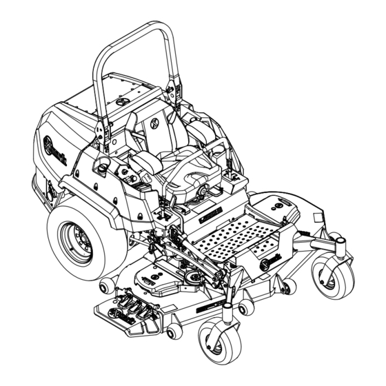
Exmark LAZER Z Series Operator's Manual
Diesel
Hide thumbs
Also See for LAZER Z Series:
- Setup instructions (7 pages) ,
- Operator's manual (96 pages) ,
- Parts manual (44 pages)
Table of Contents
Advertisement
Advertisement
Table of Contents

Related Manuals for Exmark LAZER Z Series


Summary of Contents for Exmark LAZER Z Series
- Page 1 LAZER Z DIESEL ® For Serial Nos. 402,082,300 & Higher Part No. 4503-837 Rev. B...
- Page 2 To acquire a spark arrester for your unit, see your Engine Service Dealer. For all models that do not have Exmark engines, please refer to the engine manufacturer's information included with the machine. For models with Exmark engines, refer to this manual for information.
-
Page 3: Introduction
All Exmark parts are thoroughly tested and inspected before leaving the factory, however, attention is required on your part if you are to obtain the fullest measure of satisfaction and performance. -
Page 4: Table Of Contents
Contents Deck Belt Tension ..........61 Parking Brake Adjustment ......61 Motion Control Linkage Adjustment ....62 Introduction ............3 Motion Control Damper Adjustment....63 Safety ..............5 Caster Pivot Bearings Pre-Load Safety Alert Symbol ......... 5 Adjustment ..........63 Safe Operating Practices ........5 Cleaning ............64 Safety and Instructional Decals ......11 Clean Engine and Exhaust System... -
Page 5: Safety
Exmark designed and tested this lawn mower to offer • Become familiar with the safe operation of the reasonably safe service; however, failure to comply equipment, operator controls, and safety signs. - Page 6 Safety bones, and other foreign objects which can be DANGER thrown by the machine and may cause personal In certain conditions during fueling, static injury to the operator or bystanders. electricity can be released causing a spark which can ignite fuel vapors. A fire or DANGER explosion from fuel can burn you and others In certain conditions diesel fuel is extremely...
- Page 7 Safety Operation – Before clearing blockages. – Whenever you leave the mower. WARNING • Stop engine, wait for all moving parts to stop, and Operating engine parts, especially the muffler, engage parking brake: become extremely hot. Severe burns can occur –...
- Page 8 Safety – Use an angle indicator to determine the • Do Not operate a machine under any conditions approximate slope angle of the area. where traction, steering or stability is in question. Be aware that operating the machine on wet grass, –...
- Page 9 • Ventilate when charging or using battery • Any accessories, alterations, or attachments added in an enclosed space. to the ROPS must be approved by Exmark. • Make sure venting path of battery is always open once battery is filled with Maintenance and Storage acid.
- Page 10 • Follow the attachment manufacturer's Unauthorized modifications to the original recommendation for weight limits for towed equipment or failure to use original Exmark equipment and towing on slopes. Towed parts could lead to serious injury or death. weight must not exceed the weight of the Unauthorized changes to the machine, engine, machine, operator, and ballast;...
-
Page 11: Safety And Instructional Decals
Exmark equipment dealer or labels. distributor or from Exmark Mfg. Co. Inc. • Replace all worn, damaged, or missing safety • Safety signs may be affixed by peeling off the signs. - Page 12 Safety decal116-8283 116-8283 1. Warning—read the Operator's Manual for instructions on torquing the blade bolt/nut to 55-60 ft-lb (75-81 N-m). decal109-6036 109-6036 1. Read the Operator’s manual 2. Remove the ignition key and read the instructions before servicing or performing maintenance. 3.
- Page 13 Safety decal126-8760 decal126-6464 126-8760 126-6464 96 Inch Deck Side Discharge Models 1. Height of cut 2. Range adjustment 1. Thrown objects hazard 3. Cutting/dismemberment - keep bystanders a of hand or foot - stay safe distance from the away from moving parts; machine keep all guards and shields in place.
- Page 14 Safety decal126-9351 126-9351 3TNV88C Models 1. Chassis, 15A 3. Main, 25A 2. Accessory, 15A 4. Power port, 15A decal126-9275 126-9275 decal126-9573 126-9573 60 Inch Side Discharge Deck decal126-9276 126-9276 72 Inch Side Discharge Deck decal135-1432 135-1432 decal126-9280 126-9280 72 Inch Rear Discharge Deck 1.
- Page 15 135-2838 1. Read the Operator’s manual for more information. Only use Exmark red-colored wet clutch transmission fluid P/N 135-2834. Do Not use green-colored hydraulic fluid. decal135-0670 135-0670 96 Inch Deck 1. Crushing hazard, hand - 2.
- Page 16 Safety decalptoswitch PTO Switch Symbols g232519 Fuel Cap 1. Diesel 2. Biodiesel Ready — Read the Operator’s Manual. decal126-8383 126-8383 This machine complies with the industry standard stability test in the static lateral and longitudinal tests with the maximum recommended slope indicated on the decal. It is important that each operator review the slope operation instructions in the operator’s manual and review the conditions in which the machine is being operated to determine if the machine may be operated in the conditions that day and on that site.
- Page 17 Safety decal126-9278 126-9278 Models with 60 or 72 Inch Decks 1. Engine—Off 4. Push the bottom of the button to lower the deck. 2. Engine—On 5. Push the top of the button to raise the deck. 3. Engine—Start decal126-9279 126-9279 Models with 60 or 72 Inch Decks 1.
- Page 18 Safety decal126-9947 126-9947 96 Inch Deck 1. Read and understand the Operator’s Manual before 7. Check the oil level in the jackshaft. servicing the machine. 2. Time interval 8. Grease the deck drive PTO; refer to the Operator’s Manual for further instructions. 3.
- Page 19 Safety decal135-0398 135-0398 96 Inch Deck 1. Engine—Off 4. Push bottom of button to lower center deck and outer wings 2. Engine—On 5. Push top of button to raise center deck and fold up outer wings 3. Engine—Start...
-
Page 20: Specifications
• Engine Specifications: See your Engine Owner’s ◊ No. 1-D S15 Manual ◊ No. 2-D S15 • Engine Oil Type: Exmark Premium Engine Oil is recommended. Use summer-grade diesel fuel (No. 2-D) at temperatures above -7°C (20°F) and If using an alternative, use high-quality, low-ash winter-grade fuel (No. - Page 21 Cooling System • Wheel Motors: Two Hydro-Gear “H” Motors • Fan: Belt driven ™ • Hydraulic Oil Type: Exmark Ruby Tran oil. • Coolant Liquid: 50/50 solution of water and Part No. 135-2834 permanent ethylene glycol antifreeze. The use of •...
- Page 22 Specifications P/N 135-2252: 10 microns – 96 inch Deck: 24.5 inches (62.2 cm) (4 ea.) • Speeds: • Blade Spindles: Solid steel spindles with 1.0 inch (25 mm) I.D. bearings. – 3TNV80FT: • Deck Drive: ◊ 0-11.0 mph (17.7 km/hr) forward. –...
-
Page 23: Dimensions
Specifications Dimensions Tread Width: (Center to Center of Tires, Widthwise) Overall Width: Drive Wheels Side Discharge Units: 60 and 72 inch Decks 96 inch Deck 44.1 inches (112 cm) 46.1 inches (117 cm) 60 inch Deck 72 inch Deck Without Deck 55.6 inches 60.0 inches Caster Wheels... -
Page 24: Torque Requirements
Product Overview Curb Weight Product Overview 3TNV80FT Models: Discharge 60 inch Deck 72 inch Deck Side 1915 lb (869 kg) 1930 lb (875 kg) Rear — 2041 lb (926 kg) 3TNV88C Models: Discharge 60 inch 72 inch 96 inch Deck Deck Deck Side... -
Page 25: Operation
Operation Operation Note: Determine the left and right sides of the machine from the normal operating position. Controls Motion Control Levers The motion control levers located on each side of the console control the forward and reverse motion of the machine. Moving the levers forward or backward turns the wheel on the same side forward or reverse g237956... - Page 26 Operation g225792 Figure 7 1. RED Equipped Logic 3. Ignition switch Display Unit (LDU) 2. Deck lift switch (also 4. PTO engagement switch folds wings on 96 inch deck) The RED Equipped Logic Display Unit (LDU) g008593 Figure 6 monitors and displays machine system information. 1.
- Page 27 Operation information, reset counters, modify system settings, • Continuous sound indicates critical errors. and troubleshoot the equipment. • Chirping sound indicates less critical errors, such as required maintenance or service intervals. RED Equipped Information Screen Refer to the RED Equipped User’s Guide-Diesel Located at the top of the LDU, above the push Models for more information.
- Page 28 Operation glow symbol on the RED LDU will disappear and the engine will crank when turned to “START”. Note: The system will allow the unit to start with the PTO switch in the pulled out (up) position, but will not engage the blades. The PTO engagement switch must be reset to engage the PTO.
-
Page 29: Pre-Start
Operation Important: Always use the seat belt with – Push the top of the button to raise the deck. the roll bar in the operate (raised) position. – Push the bottom of the button to lower the Ensure that the rear part of the seat is secured deck. - Page 30 Operation Ensure that the rear part of the seat is secured with the seat latch. Starting the Engine Move the motion control levers out to the neutral lock position. Pull up and back on the parking brake lever to engage the parking brake. Push down on the PTO switch to the “disengage”...
- Page 31 Operation DANGER An uncovered discharge opening will allow objects to be thrown in an operator’s or bystander’s direction. Also, contact with the blade could occur. Thrown objects or blade contact can cause serious injury or death. Never operate the mower with the discharge deflector raised, removed, or altered unless there is a grass collection system or mulch kit in place and working properly.
- Page 32 Operation Driving the Machine CAUTION Machine can spin very rapidly by positioning one lever too much ahead of the other. Operator may lose control of the machine, which may cause damage to the machine or injury. • Use caution when making turns. •...
- Page 33 Operation To turn right, release pressure on the RH motion control lever and the rear of the machine will move towards the rear and to the right. To turn left, release pressure on the LH motion control lever and the rear of the machine will move towards the rear and to the left.
- Page 34 Operation Insert the height adjustment pin into the hole Middle hole (0 on decal) 2–4.5 inches (51–114 mm) corresponding to the desired cutting height. Bottom hole (+1 on decal) 3–5.5 inches (76–140 mm) See the decal on the side of the deck lift plate for cut heights.
- Page 35 Operation mm) clearance to the ground to minimize gouging and roller wear or damage. g035118 Figure 19 For cutting heights above 3.5 inches (90 mm) use the bottom hole. The rollers will still be effective against scalping. g023992 Figure 20 1.
-
Page 36: Transporting
Operation g238205 Figure 23 1. Bolt 3. Nut 2. Bumper Move each bumper to the desired position and g238020 Figure 22 secure them with the bolts and nuts. Underside of 96 Inch Deck Note: Only use the top or center sets of holes to 1. - Page 37 Operation procedure. Back up ramps and drive forward down ramps (Figure 26). g225819 Figure 24 g028043 60 and 72 inch Models Figure 26 (Six locations-three on left, three on right) 1. Back up ramps 2. Drive forward down ramps 1. Tie-down location Important: Do not use narrow individual ramps for each side of the machine.
- Page 38 Operation WARNING Loading a machine onto a trailer or truck increases the possibility of tip-over and could cause serious injury or death. • Use extreme caution when operating a machine on a ramp. • Ensure that the ROPS is in the up position and use the seat belt when loading or unloading the machine.
-
Page 39: Maintenance
• Drain fuel filter/water separator. • Clean the engine cooling system. • Change the engine oil and filter if not using Exmark Premium Engine Oil but any oil Every 200 hours meeting API CJ-4 or higher or as stated in the Specifications Section. -
Page 40: Periodic Maintenance
Maintenance Maintenance Service Maintenance Procedure Interval • Change the hydraulic filter and fluid if using Exmark Ruby Tran™ Fluid. Every 800 hours • Inspect the engine valve clearance. Every 2,000 hours • Change engine coolant. • Check the battery charge. - Page 41 Maintenance short lengths to reduce voltage drop between Voltage Percent Maximum Charging systems. Make sure the cables are color coded or Reading Charge Charger Interval labeled for the correct polarity. Settings 12.6 or 100% 16 volts/7 CAUTION Charging greater amps Required Connecting the jumper cables incorrectly 12.4 –...
-
Page 42: Check Mower Blades
Maintenance g006780 Figure 29 g012785 Figure 28 1. Install bushing in blade prior to installing bushing in spindle. 1. Positive (+) cable on discharged battery 2. Positive (+) cable on booster battery 3. Negative (–) cable on the booster battery Install bushing/blade assembly into spindle. - Page 43 Always install the original Exmark blades, blade bushings, and blade bolts as shown.
-
Page 44: Check Safety Interlock System
Maintenance Check Safety Interlock System Service Interval: Before each use or daily Important: It is essential that operator safety mechanisms be connected and in proper operating condition prior to use. Note: If machine does not pass any of these tests, Do Not operate. Contact an Authorized Service Dealer. Note: To prevent engine cut-outs on rough terrain, the seat has a 1/2 second time delay before the engine begins to shutdown. - Page 45 Maintenance Check Engine Starting Circuit Chart Note: In the Check Engine Starting Circuit Chart, the state of system item that is bold is being checked in each scenario. System Parking Brake Motion Control Levers Operator Outcome (Blades) Operator Starter must Engaged Disengaged Both levers moved in, or either...
- Page 46 Maintenance Check Shutdown Circuit Chart (continued) System Engine Parking Motion Control Operator Outcome PTO (Blades) Brake Levers Engine must Running idle Disengaged Engaged Both levers moved in Raise off of seat (but begin shutdown (1/3 throttle or don’t get within 1 second efficient mode) off) Running idle...
-
Page 47: Check Rollover Protections Systems (Roll Bar) Knobs
Maintenance Check Rollover Protections under severe conditions. See the Engine Owner's Systems (Roll Bar) Knobs Manual for additional information.) Service Interval: Before each use or daily Stop engine, wait for all moving parts to stop, and Check that both the mounting hardware and the remove key. -
Page 48: Check Hydraulic Fluid Level
Maintenance g228816 Figure 33 1. Full 2. Add g231764 Figure 32 If fluid is needed add enough oil to put the level 1. Fill plug and dipstick in between the two marks on the dipstick. Important: Do Not overfill. If the lubricant level is low, add enough lubricant until the level is between the marks on the Replace the dipstick and fill cap;... -
Page 49: Lubricate Grease Fittings
Maintenance Lubricate Grease Fittings 96 inch Model Note: See chart for service intervals. Lubrication Chart Stop engine, wait for all moving parts to stop, and Fitting Initial Number of Service remove key. Engage parking brake. Locations Pumps Places Interval Lubricate fittings with one to two pumps of 1. -
Page 50: Drain Fuel Filter/Water Separator
Pack the bearings with a NLGI grade #1 multi-purpose grease. Insert one bearing, one new seal into the wheel. Note: Seals (Exmark P/N 103-0063) must be replaced. If the axle assembly has had both spacer nuts removed (or broken loose), apply a thread locking adhesive to one spacer nut and thread onto the axle with the wrench flats facing outward. -
Page 51: Change Fuel Filter/Water Separator
Maintenance g231880 Figure 35 1. Filter Water should drain. When fuel begins to flow from the filter, tighten the drain plug. Important: Water or other contaminants in fuel can severely damage fuel pump and/or the other engine components. Change Fuel Filter/Water Separator Service Interval: Every 400 hours/Yearly (whichever comes first) -
Page 52: Change Deck Gearbox Oil
Before reinstalling new filter, apply a thin coating Disengage the PTO, move the motion control of Exmark 4-Cycle Premium Engine Oil on the levers to the neutral-lock position, and engage the surface of the rubber seal. Turn filter clockwise parking brake. - Page 53 After first 200 hours plug *Every 400 hours thereafter Unscrew the filter to remove and allow fluid to *May need more often under severe drain from reservoir. conditions. Important: Before reinstalling new Replace the plugs. filter, apply a thin coat of Exmark Ruby...
-
Page 54: Check Engine Coolant Level
Figure 40 Important: Exmark will not assume responsibility for damage caused by improper 1. Expansion tank substitutions. Raise the rear of machine up and support with... -
Page 55: Thread Locking Adhesives
Maintenance overflow bottle on the left side of the engine as WARNING required to bring the level up to the indicator line Engine coolant is hot and pressurized and on the bottle. radiator and surrounding parts are hot. Spray or steam from hot, pressurized liquid in the WARNING engine cooling system and touching a hot Engine compartment contains open belt... -
Page 56: Dielectric Grease
Maintenance Adjustments On threads of Blade Bolts. See Check Mower Blades section. Note: Disengage PTO, shut off engine, wait for all moving parts to stop, engage parking brake, and Dielectric Grease remove key before servicing, cleaning, or making any adjustments to the unit. Dielectric grease is used on all blade type electrical connections to prevent corrosion and loss of contact. - Page 57 Maintenance Insert the height adjustment pin into the 3 inches (76 mm) cutting height location. Release the transport lock and allow the deck to lower to the cutting height. Raise the discharge deflector (side discharge units only). Measure from the level surface to the front tip of the center blade.
-
Page 58: Deck Leveling-96 Inch Models
Maintenance the deck is too high, loosen the single point adjustment bolt by rotating it counterclockwise. Note: Loosen or tighten the single point adjustment bolt enough to move the height of cut plate mounting bolts at least 1/3 the length of the available travel in their slots. - Page 59 Maintenance g239055 Figure 47 1. Unlock cam lock 3. Lanyard 2. Clevis pin Insert the height adjustment pin into the 4 inch (102 mm) cutting height location and reinstall the lanyard. Lock the left and right wing deck cam locks. Start engine.
- Page 60 Maintenance If the four deck adjusters do not have enough adjustment to achieve accurate cut height with the desired rake, the single point adjustment can be utilized to gain more adjustment To adjust the single point system, first loosen the front and rear height of cut plate mounting bolts.
-
Page 61: Deck Belt Tension
Maintenance Deck Belt Tension Self-tensioning - No adjustment necessary. Parking Brake Adjustment Service Interval: After the first 100 hours Every 400 hours thereafter Check to make sure brake is adjusted properly. This procedure must be followed after the first 100 hours or when a brake component has been removed or replaced. -
Page 62: Motion Control Linkage Adjustment
Maintenance Note: The brake should fully disengage when the brake is in the “released” position. Rotate the drive wheel release handle to the “operating” position. Refer to the Drive Wheel Release Valves section in Operation. Install the rear tires and torque lug nuts to 85-105 ft-lb (115-142 N-m). -
Page 63: Motion Control Damper Adjustment
Maintenance Motion Control Damper Loosen lock nuts from the ball joints at each end of the pump control linkage (Figure 53). Adjustment The top damper mounting bolt can be adjusted to obtain a more desired motion control lever resistance. See Figure 54 for mounting options. g228557 Figure 53 Right-Hand Side of Unit... -
Page 64: Cleaning
Maintenance Cleaning Clean Engine and Exhaust System Area Service Interval: Before each use or daily (May be required more often in dry or dirty conditions.) CAUTION Excessive debris around engine and exhaust system area can cause engine, exhaust area, and hydraulic system to overheat which can create g228558 a fire hazard. -
Page 65: Clean Debris From Machine
Maintenance Blow through with low pressure air from both Inspect the engine-valve clearance. Refer to the directions. If debris remains, repeat until clean. engine owner’s manual. Lower hood. Waste Disposal Start the engine to ensure the fan is functioning properly. Motor Oil Disposal Clean Debris From Machine Engine oil and hydraulic oil are both pollutants to... -
Page 66: Troubleshooting
Troubleshooting Troubleshooting Important: It is essential that all operator safety mechanisms be connected and in proper operating condition prior to mower use. When a problem occurs, do not overlook the simple causes. For example: starting problems could be caused by an empty fuel tank. The following table lists some of the common causes of trouble. - Page 67 Troubleshooting Problem Possible Cause Corrective Action Mower pulls left or right (with levers fully 1. Tracking needs adjustment. 1. Adjust the tracking. forward) 2. Tire pressure in drive tires not correct. 2. Adjust tire pressure in the drive tires. 3. Reverse indicator and motion control 3.
-
Page 68: Schematics
Schematics Schematics Electrical Schematic—Yanmar Engine 3TNV80FT g232909... - Page 69 Schematics Electrical Schematic—Yanmar Engine 3TNV88C g232910...
- Page 70 Schematics Electrical Schematic—Tractor (RED) 60 and 72 Inch Models g233006...
- Page 71 Schematics Electrical Schematic—Tractor (RED) 96 Inch Models g241314...
- Page 72 Schematics Hydraulic Diagram—60 and 72 Inch Models g238475...
- Page 73 Schematics Hydraulic Diagram—96 Inch Models g239212...
- Page 75 g011841 Figure 56 This page may be copied for personal use. 1. The maximum slope you can operate the machine on is 15 degrees. Use the slope indicator to determine the degree of slope of hills before operating. Do Not operate this machine on a slope greater than 15 degrees. Fold along the appropriate line to match the recommended slope.
- Page 76 Pack) or Fill in Below Engine Model No. and Spec. No. Model No. Engine Serial No. (E/No) Serial No. ©2018 Exmark Mfg. Co., Inc. Part No. 4503-837 Rev. B 2101 Ashland Ave (402) 223-6375 Beatrice, NE 68310 Fax (402) 223-5489...
Need help?
Do you have a question about the LAZER Z Series and is the answer not in the manual?
Questions and answers