Advertisement
INSTALLATION, COMMISSIONING & SERVICING INSTRUCTIONS
These appliances have been tested and certified by B G Technology for use with PROPANE gas G31.
Note: If a HIJAN 6P circulator is fitted, the relevant Installation, Commissioning and Servicing instructions provided with that
appliance must also be observed.
1.
1
2
3
7
4
11
9
8
1.1
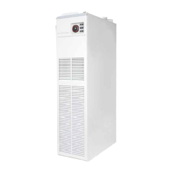
HI-SPEC J32P is an open-flued, fan assisted downflow, ducted warm air heater, supplied with conventional control. A
HIJAN 6P circulator is available as an option. HI-SPEC J32RP, which has an integral rear rising duct is also available as
an option. A Spillage Monitoring Device (TTB) is fitted which senses the temperature in the draught diverter, and shuts
down the appliance when this temperature rises due to the presence of flue gases.
1.2
The Air heater output is 8.30kW (29.88MJ/h, 28,320Btu/h) . "Summer air circulation" of unheated air is available by
manual selection (see User's Instructions). HIJAN 6P output is 3.56kW (12.8MJ/h, 12,150Btu/h).
These instructions are to be left with the User or adjacent to the Gas Meter
HI-SPEC J32P and HI-SPEC J32RP
WARM AIR HEATERS
with Conventional Control
G.C. No 42 451 07 HI-SPEC J32P
G.C. No 42 451 08 HI-SPEC J32RP
BRIEF DESCRIPTION
Fig. 1
THIS APPLIANCE CONFORMS TO BS EN 55014
5
13
1
2
14
3
4
5
6
7
8
9
10
11
6
12
13
12
14
10
1
Publication No. ZZ 982/7
February 2007
Air Filter
Air circulating fan
Heat exchanger access cover
Data plate
Time control
Multifunctional control
Fan Delay Control/Limit Switch
Pilot burner
Burner Assembly
Gas connection
Heat shield
Piezo igniter unit
Spillage monitoring Device (TTB)
(Air heater)
Spillage monitoring Device (TTB)
(Water Heater)
Advertisement
Table of Contents

Related Manuals for Johnson & Starley HI-SPEC J32P


Summary of Contents for Johnson & Starley HI-SPEC J32P
- Page 1 Fig. 1 HI-SPEC J32P is an open-flued, fan assisted downflow, ducted warm air heater, supplied with conventional control. A HIJAN 6P circulator is available as an option. HI-SPEC J32RP, which has an integral rear rising duct is also available as an option.
-
Page 2: Ventilation And Combustion Air
Installation shall be in accordance with the current editions of:- Building Standards (Scotland) (Consolidation) Regulations Building Regulations Gas Safety (Installation and Use) Regulations (as amended) BS 7671 Institute of Electrical Engineers (I.E.E.) Wiring Regulations BS 5482 Pt. 1 Domestic Butane- and Propane-gas-burning installations. BS 5440 Pt. -
Page 3: Duct System
VENTILATED Low level grille 288cm (44in FROM INSIDE BUILDING High level grille 144cm (22in VENTILATED Low level grille 144cm (22in FROM OUTSIDE BUILDING High level grille 72cm (11in Table 1: Minimum Effective Areas DUCT SYSTEM (See British Design Manual - Gas fired Warm Air Heating) RETURN AIR 4.1.1 All return air shall be POSITIVELY ducted from outside the compartment to the top of the unit via a return air... - Page 4 5.1.8 The flue should run as vertically as possible. Horizontal runs should be avoided if at all possible and any directional change should be as gentle as possible. If there is any doubt about the flue configuration, the equivalent flue height should be determined (see 5.1.10). 5.1.9 If the appliance to be fitted is a replacement, the old appliance should be checked for signs of spillage prior to commencement of the installation and appropriate action taken, (i.e.
- Page 5 Component Internal Size Resistance Component Internal Size Resistance (mm) Factor (mm) Factor Flue Blocks 197 x 67 0.85 per meter Bend 100 mm pipe 0.61 per 231 x 65 0.65 run 125 mm pipe 0.25 fitting 317 x 63 0.35 150 mm pipe 0.12 140 x 102...
- Page 6 Ridge Terminal 2 x 300 mm lengths 100 mm dia flue pipe = 6.2m 4.6m 4 x 1000 mm lengths bend 300 mm length bend 1.6m 2 x 300 mm lengths Flue spigot Fig. 2 Worked example of equivalent flue height 5.1.12 Special consideration must be given to external flues with a view to prevention of condensation and weathering problems.
- Page 7 5.1.15 Important: Before installing the appliance, carry out a visual check of the flue system as directed in the relevant section of BS5440 Pt. 1, then check the flue performance as follows:- Close all doors and windows in the room in which the appliance is to be installed. Introduce some heat into the flue, using a blow torch or other means.
-
Page 8: System Balancing
SYSTEM BALANCING: 6.2.1 Set the Air Heater electrical supply ON. 6.2.2 Set the SUMMER AIRFLOW switch to ‘1’. 6.2.3 Balance the system to provide the required volume proportions at the warm air outlets. Note: If the system includes ceiling diffusers, the air through these should be NOT LESS THAN 1.5m/s (300ft/min), except for very small rooms, (i.e. - Page 9 MAIN BURNER PRESSURE TEST: MAIN BURNER PRESSURE TEST AND TEMPERATURE RISE CHECK: 6.4.1 6.4.1 Referring to Table 4 ensure that the pressure test gauge indicates the correct burner pressure, a low pressure Referring to Table 4 and Fig. 4 below, ensure that the pressure test gauge indicates correct pressure, adjusting the supply pressure if required.
-
Page 10: Safety Checks
SAFETY CHECKS: 6.8.1 Check for gas soundness within the appliance. 6.8.2 Spillage test: Carry out a full spillage test as follows, and ensure that the flue operates effectively with all doors closed and any extractor fans in operation. NOTE: If an extractor fan is situated in an adjoining or adjacent room, carry out the spillage test with the interconnecting doors open. -
Page 11: Air Volume
mbar in.wg. 0.50 0.20 0.375 0.15 0.25 0.10 0.125 0.05 400 ft /min 0.09 0.12 0.14 0.17 0.19 m /sec AIR VOLUME Table 5 Fan Performance Curve INSTRUCTIONS FOR USERS If the building is unoccupied, ensure that the Instructions for User are left taped to the air heater for the User, and Installation Instructions are left at or near the air heater for use on future service calls. - Page 12 8.1.9 Using a torch or similar, introduce a light source into the heat exchanger burner aperture and upper access port, and again examine the heat exchanger for signs of cracks or holes, particularly around welded joints, whilst again viewing through the Fan Aperture. 8.1.10 Refit the Air Circulation fan, Burner and Controls Assembly, and air filter/air cleaner.
- Page 13 MULTIFUNCTIONAL CONTROL REMOVAL: 8.5.1 Remove the Burner and Controls Assembly as detailed in 8.2 8.5.2 Disconnect the Thermocouple at the Multifunctional Control, avoiding damage to the capillary. 8.5.3 Disconnect the Pilot Feed Pipe from the Multifunctional Control. 8.5.4 Disconnect the Multifunctional Control input and output supply feeds. 8.5.5 Refitting or replacement is in reverse order.
- Page 14 8.10 TIME CONTROL and SWITCH REMOVAL: 8.10.1 Ensure that the electrical supply is isolated. 8.10.2 Remove the appliance louvre door, release the 2 x securing screws and hinge down the fan chamber door. Time Control removal: 8.10.3 Disconnect conductors ‘C1’, ‘C2’, ‘C3’ and ‘C5’ from the Time control. 8.10.4 Release the 2 x fixing screws, and withdraw the Time control.
-
Page 15: Defect Diagnosis
DEFECT DIAGNOSIS IMPORTANT: If an electrical defect occurs after installation of the appliance; preliminary earth continuity, polarity, and resistance to earth checks should be carried out with a multimeter. On completion of any maintenance/fault-finding task that has required the breaking and remaking of electrical connections, then checks of continuity, polarity, and resistance to earth must be repeated. - Page 16 Main burner lights i. Loose electrical connection Check connections. but fan fails to run at fan control. after approx. 3 min. ii. Fan delay control faulty. Replace Fan Delay/Limit Switch. iii. Faulty fan assembly. Replace, taking care not to damage impeller.
- Page 18 Park conns when no clock fitted or for external prog. 230V NO CLOCK OPTION 230V Cont. AH(S5) Timed T3.15A 230V 50Hz Timed Supply EXTERNAL PROG. Park S8 when no FUSE OPTION water htr. or for ext. prog. 230V Continuous Timed 230V Limit Switch...
- Page 19 Fig. 7, PRINCIPAL DIMENSIONS (mm)
-
Page 20: Short List Of Spares
SHORT LIST OF SPARES HI-SPEC J32P and HI-SPEC J32RP G.C No MFR’S No DESCRIPTION 245 501 1000-0500370 Fan Assembly H26-712 1000-0709640 Multifunctional Control Honeywell V8600C 1129 BOS 02397/2 Pilot Burner 1000-0701440 Pilot Injector (No 19) 1000-0704730 Pilot Feed Pipe 390 210...
Need help?
Do you have a question about the HI-SPEC J32P and is the answer not in the manual?
Questions and answers