Johnson & Starley HI-SPEC J40 Installation, Commissioning & Servicing Instructions
System e-t and conventional control
Hide thumbs
Also See for HI-SPEC J40:
Table of Contents
Advertisement
INSTALLATION, COMMISSIONING & SERVICING INSTRUCTIONS
This appliance has been tested and certified by B G Technology for use with natural gas G20.
Note: If an ELJAN 6 circulator is fitted, the relevant Installation, Commissioning and Servicing instructions provided with that
appliance must also be observed.
1.
1
2
3
7
4
11
8
9
1.1
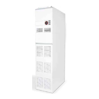
HI-SPEC J40 is an open-flued, fan assisted downflow, ducted warm air heater, which may be supplied with SYSTEM E-T
or BASIC control. An ELJAN 6 circulator is available as an option. A Spillage Monitoring Device (TTB) is fitted
which senses the temperature in the draught diverter, and shuts down the appliance when this temperature rises due to the
presence of flue gases.
1.2
The Air heater output can be adjusted between 8.8kW (31.65MJ/h, 30,000Btu/h) and 11.2kW (42.2MJ/h, 40,000Btu/h) .
"Summer air circulation" of unheated air is available by manual selection (see User's Instructions). ELJAN 6 output is
3.32kW (11.5MJ/h, 11,340Btu/h).
HI-SPEC J40 WARM AIR HEATER
SYSTEM E-T and Conventional Control
G.C. No 42 451 09
BRIEF DESCRIPTION
Fig. 1
THIS APPLIANCE CONFORMS TO BS EN 45014
5
13
1
2
3
4
5
6
7
8
9
10
11
12
13
6
12
10
1
Publication No. ZZ 815/9.
October 2006
Air Filter
Air circulating fan
Heat exchanger access cover
Data plate
Time Control
Multifunctional Control
Fan Delay Control /Limit Switch
Pilot Burner
Burner Assembly
Gas connection
Heat shield
Piezo igniter unit
Spillage monitoring Device (TTB)
Advertisement
Table of Contents

Related Manuals for Johnson & Starley HI-SPEC J40


Summary of Contents for Johnson & Starley HI-SPEC J40
- Page 1 Fig. 1 HI-SPEC J40 is an open-flued, fan assisted downflow, ducted warm air heater, which may be supplied with SYSTEM E-T or BASIC control. An ELJAN 6 circulator is available as an option. A Spillage Monitoring Device (TTB) is fitted which senses the temperature in the draught diverter, and shuts down the appliance when this temperature rises due to the presence of flue gases.
-
Page 2: Ventilation And Combustion Air
Installation shall be in accordance with the current editions of:- Building Standards (Scotland) (Consolidation) Regulations Building Regulations Gas Safety (Installation and Use) Regulations (as amended) BS 7671 Institute of Electrical Engineers (I.E.E.) Wiring Regulations BS 6891 Installation of Low Pressure Gas Pipework of up to 28mm (R1) in domestic premises (2nd family gases). BS 5440 Pt. -
Page 3: Duct System
VENTILATED Low level grille 352cm (54in FROM INSIDE BUILDING High level grille 176cm (27in VENTILATED Low level grille 176cm (27in FROM OUTSIDE BUILDING High level grille 88cm (13in Table 1 Minimum Effective Areas DUCT SYSTEM (See British Design Manual - Gas fired Warm Air Heating) RETURN AIR 4.1.1 All return air shall be POSITIVELY ducted from outside the compartment to the top of the unit via a return air... - Page 4 5.1.7 All materials shall be in accordance with Building Regulations requirements. 5.1.8 The flue should run as vertically as possible. Horizontal runs should be avoided if at all possible and any directional change should be as gentle as possible. If there is any doubt about the flue configuration, the equivalent flue height should be determined (see 5.1.10).
- Page 5 Component Internal Size Resistance Component Internal Size Resistance (mm) Factor (mm) Factor Flue Blocks 197 x 67 0.85 per meter Bend 100 mm pipe 0.61 per 231 x 65 0.65 run 125 mm pipe 0.25 fitting 317 x 63 0.35 150 mm pipe 0.12 140 x 102...
- Page 6 Ridge Terminal 2 x 300 mm lengths 100 mm dia flue pipe = 6.2m 4.6m 4 x 1000 mm lengths bend 300 mm length 1.6m bend 2 x 300 mm lengths Flue spigot Fig. 2 Worked example of equivalent flue height Note: Ventilation of the compartment, room or internal space in which the appliance is to be installed must be checked for compliance with the requirements of BS 5440 Part 2 ( Ref.
- Page 7 ZZ815/7 5.1.15 Important: Before installing the appliance, carry out a visual check of the flue system as directed in the relevant section of BS5440 Pt.1, then check the flue performance as follows:- Close all doors and windows in the room in which the appliance is to be installed. Introduce some heat into the flue, using a blow torch or other means.
-
Page 8: System Balancing
COMMISSIONING PREPARATION: 6.1.1 Ensure that: Gas and Electrical supplies are OFF. Filter, fan and fan compartments are free from obstructions. All registers or grilles are open and conform to design specifications. Return, relief and ventilation air installations are adequate. SYSTEM BALANCING: 6.2.1 Set the Air Heater electrical supply ON. - Page 9 MAIN BURNER PRESSURE TEST: NOTE: AIR HEATER BURNERS ARE FACTORY SET TO PROVIDE A NOMINAL HIGH PRESSURE OUTPUT AS DETAILED IN SUB PARA 1.2 6.4.1 Referring to Table 4 and Fig.4 below, ensure that the pressure test gauge indicates the correct burner pressure, resetting if required as follows: At the Multifunctional Control: Remove the Burner Pressure Adjuster cover.
-
Page 10: Safety Checks
AUTOMATIC CONTROLS CHECK: 6.7.1 Ignite the Pilot and Main Burners and allow to operate for 15 minutes to ensure stability. 6.7.2 Set the TIME CONTROL to ‘ON’. 6.7.3 Turn the Thermista-stat or room thermostat slowly clockwise until the Main Burner ignites. 6.7.4 Ensure that the fan starts to operate after a short period (approx. -
Page 11: Air Volume
LOW RATE MEDIUM RATE HIGH RATE MJ/h Btu/h MJ/h Btu/h MJ/h Btu/h INPUT 11.75 42.35 40,100 13.5 48.58 46,050 15.18 54.65 51,800 OUTPUT 8.79 31.65 30,000 10.26 36.92 35,000 11.72 42.2 40,000 Gas rate cv 1.08m /h (38.4ft 1.24m /h (44.1ft 1.40m /h (49.8ft 1037Btu/ft... -
Page 12: Maintenance
7.2.9 That the red instructions for safe use have been pointed out and understood. 7.2.10 That expert help must be obtained if persistent failure of the pilot burner occurs. MAINTENANCE IMPORTANT: Ensure that the gas and electricity supplies are isolated before commencing any maintenance or replacement of components. - Page 13 8.5.3 Release the Pilot Feed Pipe from the pilot injector. 8.5.4 Release the retaining nut and withdraw the Thermocouple from the Pilot Burner Assembly, taking care to avoid causing damage to the capillary. 8.5.5 Release the Electrode securing nut from the Pilot Burner Assembly and withdraw the Electrode. 8.5.6 Release the two screws securing Pilot Burner Assembly to the main burner, and remove Pilot Burner Assembly.
- Page 14 Water Pump from connection block terminals ‘12’ (L) and ‘11’ (N), Cleanflow from connection block terminals ‘19’ (24V) and ‘20’ (0V), Earth lead from the fan chamber floor, Both model types: 8.9.5 Disconnect the 2 x Spillage switch connections from terminal block terminal ‘15’, and the relay module ‘COMM’...
- Page 15 8.14.3 Disconnect the TTB from its conductors. 8.14.4 Release 2 x screws securing the TTB Bracket to the fan chamber floor, and withdraw the TTB Bracket. 8.14.5 Refitting or replacement is in reverse order. 8.15 HEAT EXCHANGER ACCESS: 8.15.1 Ensure that the electrical supply is isolated. 8.15.2 Remove the appliance louvre door.
- Page 16 closed. v. Spillage of flue gases. Carry out spillage test and rectify. vi. Spillage monitor device (TTB) Replace Spillage device (TTB) faulty. SYSTEM E-T models: Incorrect operation Fault related to SYSTEM E-T Consult diagnostic chart and follow of fan or main burner. Control system (refer to pages 17-21) recommended procedure.
- Page 17 iii. Fan speed setting too high. Adjust fan speed. Fan runs for excessive i. Fan delay control faulty. Replace. period or operates intermittently after main burner shuts down. Diagnostic LED The SYSTEM E-T module is fitted with a diagnostic light emitting diode (LED) which is visible through a hole in the module cover, as shown in Fig.
- Page 18 MAIN BURNER NOT CYCLING ROOM TEMPERATURE TOO HIGH) DISCONNECT THERMISTA-STAT DOES REPLACE BURNER THERMISTA-STAT OUT? DISCONNECT MULTIFUNCTIONAL CONTROL AT TERMINAL 15 REPLACE DOES ELECTRONICS BURNER GO OUT? MODULE REPLACE MULTIFUNCTIONAL CONTROL FAN CONTINUES TO RUN, OR CYCLES AFTER HEATING IS TURNED OFF DISCONNECT TERMINALS ‘17’...
- Page 19 FAN OPERATES, BUT BURNER CYCLES BEFORE REQUIRED TEMPERATURE IS REACHED DISCONNECT THERMISTA-STAT AT TERMINALS ‘7’ & ‘8’, LINK TERMI- NALS ‘7’ & ‘TEST’ DO NOT LINK ‘7’ &’8’ DOES THE BURNER REPLACE CONTINUE TO THERMISTA-STAT CYCLE? CHECK RETURN AIR PATH FOR RESTRICTIONS DOES THE BURNER...
- Page 20 FAN RUNS BUT MAIN BURNER NOT OPERATING ‘SUMMER SET ‘SUMMER AIRFLOW’ AIRFLOW SWITCH TO SWITCH ‘0’ SET TO ‘0’ THERMISTA CONNECT -STAT THERMISTA-STAT CONNECTED THERMISTA -STAT SET TO ‘SUMMER AIRFLOW SET THERMISTA-STAT TO REQUIRED TEMPERATURE SETTING DOES FAULT FAN STILL CLEARED RUN ? DISCONNECT THERMISTA-STAT AT...
- Page 21 MAIN BURNER NOT OPERATING TURN GAS PILOT LIT ? ON ? IS 230V LIGHT SWITCH ON SUPPLY PILOT 230 V ON ? IS TIME CONTROL & SET CONTROLS THERMISTA- CORRECTLY STAT CORRECTLY SET ? DISCONNECT THERMISTA-STAT AT TERMINALS ‘7’ & ‘8’, LINK TERMI- NALS ‘7’...
- Page 22 ZZ815/7...
- Page 24 SYSTEM E-T Electronic module...
-
Page 26: Front View
FRONT VIEW SIDE VIEW 120 dia. BASE VIEW PLAN VIEW Fig. 7a, SYSTEM E-T FUNCTIONAL DIAGRAM... -
Page 27: Short List Of Spares
Fig. 7b, BASIC CONTROL FUNCTIONAL DIAGRAM Fig. 6a, SYSTEM E-T CIRCUIT DIAGRAM Fig. 6b, BASIC CONTROL CIRCUIT DIAGRAM Fig. 8, PRINCIPAL DIMENSIONS (mm) SHORT LIST OF SPARES HI-SPEC J40 G.C No MFR’S No DESCRIPTION 245 502 1000-0516580 Fan Assembly 381 627 1000-0701140 Multifunctional Control (S.I.T. - Page 28 Johnson and Starley prides itself on its ability to supply spare parts quickly and efficiently. If you have a problem in obtaining a spare part, please contact Johnson and Starley Spares Department at the address below. JOHNSON & STARLEY LTD. Telephone: (01604) 762881 Rhosili Road,...
Need help?
Do you have a question about the HI-SPEC J40 and is the answer not in the manual?
Questions and answers