Table of Contents
Advertisement
Quick Links
INSTALLATION, COMMISSIONING & SERVICING INSTRUCTIONS
1.
1
2
3
4
Key
1
2
3
4
5
6
1.1
The Johnson & Starley JANSTAR is a all mounted, room sealed, fan assisted, down flow warm air heater with SYSTEM
E-T control. It is designed for use with a concentric air inlet/flue, which enables combustion air to be admitted to the
burner, whilst combustion products are discharged to the outside, via a concentric terminal.
1.2
The air heater output varies automatically between 8.0 kW (27,300Btu/h) and 2.0 kW (6,800 Btu/h) for horizontal flued
installations, and 8.5 kW (29000Btu/h) and 2.8 kW (9600Btu/h) for vertical flued installations.
1.3
The appliance is supplied assembled for left hand return air entry. For conversion to right hand return entry, refer to
Section 4. If return air is via the top of the fan chamber, a side blanking plate (Pt No W800-0133000) is required. An
adaptor kit is available which permits the appliance to be converted to an upflow model. The appliance may be base duct
mounted. The JANSTAR is also provided with the facility for connection to a remote time control (not supplied), with
volt-free contacts (i.e. The switching supply is provided by JANSTAR), to enable selection of operating times.
1.4
A mesh filter, for air return duct mounting, is supplied as standard. However, a Cleanflow electronic filter is offered as an
alternative option.
MODULATING WARM AIR HEATER
with SYSTEM E-T Control
G.C. No 42 451 07
This appliance has been tested and certified for use with natural gas.
GENERAL DESCRIPTION
5
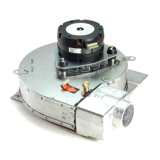
Description
Air circulating fan
Fan energy capacitor
Burner assembly
Ignition/detection electrode
Gas connection
Multifunctional control
JANSTAR Principal Components
THIS APPLIANCE CONFORMS TO BS EN 55014
JANSTAR
8
7
6
Key
7
8
9
10
11
12
Fig. 1
1
Publication No. ZZ 757/9
Description
Fan delay/ Overheat limit control
Air filter (L H shown)
Flue outlet/combustion air inlet
Fan to flue connection
Flue gas test point
Combustion air fan
June 2000
9
10
11
12
Advertisement
Table of Contents

Related Manuals for Johnson & Starley JANSTAR


Summary of Contents for Johnson & Starley JANSTAR
- Page 1 JANSTAR Principal Components The Johnson & Starley JANSTAR is a all mounted, room sealed, fan assisted, down flow warm air heater with SYSTEM E-T control. It is designed for use with a concentric air inlet/flue, which enables combustion air to be admitted to the burner, whilst combustion products are discharged to the outside, via a concentric terminal.
-
Page 2: Ventilation And Combustion Air
ZZ757/9 Installation shall be in accordance with the current editions of:- Building Standards (Scotland) (Consolidation) Regulations Building Regulations Gas Safety (Installation and Use) Regulations (as amended) BS7671 Institute of Electrical Engineers (IEE.) Wiring Regulations BS6891 Installation of Low Pressure Gas Pipework of up to 28mm (R1) in domestic premises (2nd family gases). BS5440 Pt.1 (Flues for Gas Appliances) BS5440 Pt.2 (Air Supply for Gas Appliances) BS5864 Installation of Gas Fired Ducted Air Heaters... -
Page 3: Installation Requirements
ZZ757/9 5.1.2 The return air system should be constructed of fire-resistant material. It is extremely important that the correct size of return air grilles and ducting is used. The return air duct size should be NOT LESS THAN 225mm x 200mm (9in x 8in). - Page 4 ZZ757/9 6.2.9 The flue/air duct spigot on the appliance is female. For horizontal flued appliances, the flue/air duct should be constructed that such that condensate cannot leak from the joints. Therefore, on vertical runs, all female ends should face away from the appliance, and on horizontal runs should face towards the appliance, as depicted in Fig.
- Page 5 ZZ757/9 CONDENSATE 6.3.1 When firing at low rate, the unit will produce condensate which must be drained away. A JDT1 kit, which externally drains the condensate away from the flue terminal is available for horizontal flued applications. Vertical flued applications require the fitment of an in-line condensate trap within 0.5 m of the unit, in the first vertical flue run, and before any bends in the flue run.
- Page 6 ZZ757/9 7.6.1 If the burner fails to light (amber ‘LOCKOUT’ illuminated): Reinstate the ignition sequence by allowing 10 seconds to elapse, and then press and release the ‘RESET’ button. 7.6.2 If the burner ignites but then extinguishes: An automatic purging sequence will take place, which lasts for approximately 30 seconds.
-
Page 7: Routine Maintenance
ZZ757/9 Burner pressure test point Inlet pressure test point Fig. 5 Multifunctional control INSTRUCTIONS FOR USERS If the building is unoccupied, ensure that the Instructions for User are left taped to the air heater for the User, and Installation Instructions are left at or near the air heater for use on future service calls. If the building is occupied, hand the User Instructions over and ensure that the User understands: 8.2.1 How to operate the Thermista-stat/room thermostat, time and heater ON/OFF switch and summer air circulation switch, and that the time control must be reset following a power failure. - Page 8 ZZ757/9 MULTIFUNCTIONAL CONTROL REMOVAL: 9.2.1 Ensure that the gas and electrical supplies are switched off. 9.2.2 Remove the heater front cover. 9.2.3 Remove the 2 x screws securing the heater front door, and the open front door. 9.2.4 Remove the central securing screws and disconnect the 2 x electrical plugs from the Multifunctional control. 9.2.5 Disconnect the two 6mm and one 8mm pipes from the top of the multifunctional control.
- Page 9 ZZ757/9 TRANSFORMER REMOVAL: 9.8.1 Ensure that the electrical supply is switched off. 9.8.2 Remove the heater front cover. 9.8.3 Remove the 2 x screws securing the heater front door, and open front door. 9.8.4 Disconnect the leads from the transformer. 9.8.5 Release 2 x securing screws, nuts and lock washers, and withdraw transformer from the electrical panel.
- Page 10 ZZ757/9 9.13 FAN DELAY/OVERHEAT (LIMIT) CONTROL (FDC) REMOVAL: 9.13.1 Ensure that the electrical supply is switched off. 9.13.2 Remove the heater front cover. 9.13.3 Remove the 2 x screws securing the heater front door, and open front door. 9.13.4 Disconnect the five conductors in the FDC lead from the control panel terminal strip, having first noted their positions.
-
Page 11: General Information
ZZ757/9 10.4 GENERAL INFORMATION: 10.4.1 This appliance is fitted with an automatic sequence control which also provides a spark ignition and flame detection facility. If the ignition/detection electrode fails to detect the presence of a flame during normal operating conditions, it will cause the multifunctional control to close. The control will then make one attempt at re-ignition by repeating the pre-purge/ignition cycle and then lock out (indicated by the amber light). - Page 12 ZZ757/9 AIR CIRCULATION FAN CONTINUES TO RUN OR CYCLES BURNER NOT OPERATING WHEN BURNER IS NOT ON Check that the time control is on and Thermista-stat is calling for heat. Check mains electrical supply. Check that Thermista-stat is not set to ‘Summer Airflow’. Disconnect Thermista-stat at terminals 3 &...
- Page 13 ZZ757/9 Fig. 7 JANSTAR functional flow circuit diagram Rear face Flue Spigot Fixing holes in rear face Return air plenum Warm air plenum Fig. 8 Principal dimensions (mm)
-
Page 14: Short List Of Spares
ZZ757/9 SHORT LIST OF SPARES G.C. MAKER’S DESCRIPTION E00 124 W800-0701000 Burner assembly E00 125 W800-0774000 Burner metal fibre assembly 245 549 1000-1500840 Gasket - burner top plate 398 219 1000-0704560 Injector Bray Cat 15/850 245 530 W800-0300000 Heat exchanger assembly 245 533 1000-0704500 Multifunctional control valve... - Page 15 Johnson and Starley prides itself on its ability to supply spare parts quickly and efficiently. If you have a problem in obtaining a spare part, please contact Johnson and Starley Spares Department at the address below. JOHNSON & STARLEY LTD. Telephone: (01604) 762881 Rhosili Road,...
Need help?
Do you have a question about the JANSTAR and is the answer not in the manual?
Questions and answers