Advertisement
INSTALLATION, COMMISSIONING & SERVICING INSTRUCTIONS
1.
1
2
3
4
5
6
7
8
1.1
HI-SPEC J50 is an open-flued, fan assisted downflow, ducted warm air heater, which may be supplied with MODAIRFLOW
control and in combination with an ELJAN 6 water circulator. A non-MODAIRFLOW version is available as an option.
A Spillage Monitoring Device (TTB) is fitted which senses the temperature in the draught diverter, and shuts down the
appliance when this temperature rises due to the presence of flue gases.
1.2
The air heater output can be adjusted between 11.72kW (42.2MJ/h, 40,000Btu/h) and 14.65kW (57.75MJ/h, 50,000Btu/h).
"Summer air circulation" of unheated air is available by manual selection (see User's Instructions). ELJAN 6 output is 3.32kW
(11.5MJ/h, 11.340Btu/h).
Installation shall be in accordance with the current editions of:
Building Standards (Scotland) (Consolidation) Regulations
Building Regulations
Gas Safety (Installation and Use) Regulations (as amended)
BS 7671 Institute of Electrical Engineers (I.E.E) Wiring Regulations
BS 6891 Installation of Low Pressure Gas Pipework of up to 28mm (R1) in domestic premises (2nd family gases).
BS 5440 Pt. 1 (Flues for Gas Appliances)
BS 5440 Pt. 2 (Air Supply for Gas Appliances)
BS 5864 Installation of Gas Fired Ducted Air Heaters
Model and Local Authority Bye-laws
These instructions are to be left with the User or adjacent to the Gas Meter
HI-SPEC J50 WARM AIR HEATERS
with MODAIRFLOW and non-MODAIRFLOW Control
This appliance has been tested and certified for use with natural gas
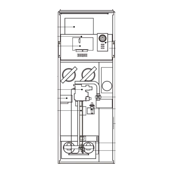
Fig. 1
THIS APPLIANCE CONFORMS TO BS EN 45014
G.C. No 42 451 13
BRIEF DESCRIPTION
16
15
FEATURES
14
1
2
3
4
5
6
7
8
9
13
10
11
12
12
13
14
11
15
16
10
9
1
Publication No. ZZ 851/6
Air circulation fan
Fuse/s
Electronics module (MODAIRFLOW)
Spillage monitoring device (TTB) (at rear)
Multifunctional control
Limit Switch
Airflow sensor (Modairflow models)
Fan delay control (non modairflow models)
Pilot burner
Burner and control assembly
Data plate
Piezo unit
Gas connection
Electrical assembly
Time control
Air filter
October 2006
Advertisement
Table of Contents

Subscribe to Our Youtube Channel
Related Manuals for Johnson & Starley HI-SPEC J50


Summary of Contents for Johnson & Starley HI-SPEC J50
- Page 1 Air filter Fig. 1 HI-SPEC J50 is an open-flued, fan assisted downflow, ducted warm air heater, which may be supplied with MODAIRFLOW control and in combination with an ELJAN 6 water circulator. A non-MODAIRFLOW version is available as an option.
-
Page 2: Ventilation And Combustion Air
IMPORTANT: STATUTE LAW DEFINES THAT ALL GAS APPLIANCES MUST BE INSTALLED BY COMPETENT PERSONS, (i.e. CORGI REGISTERED INSTALLERS) IN ACCORDANCE WITH THE GAS SAFETY (INSTALLATION AND USE) REGULATIONS (CURRENT EDITION). FAILURE TO COMPLY WITH THESE REGULATIONS MAY LEAD TO PROSECUTION. HEATER COMPARTMENT AND CLEARANCES (SEE BS 5864) IMPORTANT: If the heater is to be fitted to an existing base duct (warm air plenum), always ensure that installation is carried out such that the rear left hand corner of the heater is aligned with the rear left hand corner of the base duct, so that any... -
Page 3: Duct System
Table 1 Minimum Effective Areas DUCT SYSTEM (See British Design Manual - Gas fired Warm Air Heating) RETURN AIR 4.1.1 All return air shall be POSITIVELY ducted from outside the compartment to the top of the unit via a return air duct or, if appropriate, using a Side Return Air Kit SR50, and mechanically secured. - Page 4 5.1.7 All materials shall be in accordance with Building Regulations requirements. 5.1.8 The flue should run as vertically as possible. Horizontal runs should be avoided if at all possible and any directional change should be as gentle as possible. If there is any doubt about the flue configuration, the equivalent flue height should be determined (see 5.1.11).
- Page 5 Table 2 Resistance factors for use in calculating equivelent lengths Table 3 Inlet and outlet resistance From table 2: Other resistances of actual flue: Terminal = 2.5 Pipe bend ( 2 x 0.61) = 1.22 Pipe (4 x 1m @ 0.78) = 3.12 (5 x 0.3m @ 0.78) = 1.17...
- Page 6 Ridge Terminal 2 x 300 mm lengths 100 mm dia flue pipe = 6.2m 4.6m 4 x 1000 mm lengths bend 300 mm length bend 1.6m 2 x 300 mm lengths Flue spigot Fig. 2 Worked example of equivalent flue height 5.1.12 Where flue blocks are used, builders should ensure that no obstruction is created during erection.
- Page 7 DRAUGHT DIVERTER & DEFELCTOR PLATE: 5.4.1 The HI-SPEC J50 heater is supplied with a draught diverter which houses the TTB, and which requires fitting to the rear of the heater prior to installation, using 6 x 4mm screws and lock washers (provided). Connect the TTB to the terminal block situated on the rear upper left hand corner of the appliance.
-
Page 8: System Balancing
HEATER DEFLCTOR PLATE COMMISSIONING PREPARATION: 6.1.1 Ensure that: Gas and Electrical supplies are OFF. 130mm Filter, fan and fan compartments are free from obstructions. All registers or grilles are open and conform to Fig. 3 design specifications. Deflector Plate Fitted Return, relief and ventilation air installations are adequate. -
Page 9: Temperature Rise Check
6.3.6 Ensure that the pilot flame envelops the thermocouple tip, adjusting the Pilot Adjuster as required (Refer Figs. 4 and 6.3.7 Set the Heater Electricity supply ON. 6.3.8 Set the Time Control to the required Heating On periods. 6.3.9 Set the Selector switch to ‘TIMED’. 6.3.10 Set the Thermista-stat or room thermostat to MAXIMUM. -
Page 10: Safety Checks
Note: Tapping 1 = 150V, TAPPING 2 = 170V, TAPPING 3 = 190V, TAPPING 4 = 210V, TAPPING 5 = 230V. AUTOMATIC CONTROLS CHECK: 6.7.1 Set the TIME CONTROL to ‘ON’. 6.7.2 Turn the Thermista-stat or room thermostat slowly clockwise until the Main Burner ignites. 6.7.3 Ensure that the fan starts to operate after a short period (approx. -
Page 11: Air Volume
mbar in.wg. 0.50 0.20 0.375 0.15 Response Area 0.25 0.10 600 ft /min 0.165 0.189 0.212 0.236 0.256 0.283 m /sec AIR VOLUME Table 5 Fan Performance Curve 6.8.4 Turn the gas supply ON at service cock. 6.8.5 Switch the appliance electrical supply OFF. 6.8.6 Disconnect the fan at the flying socket 6.8.7 Switch the appliance electrical supply ON. -
Page 12: Maintenance
MAINTENANCE IMPORTANT: Ensure that the gas and electricity supplies are isolated before commencing any maintenance or replacement of components. After completion of any maintenance, always test for gas soundness and carry out a complete functional test of the appliance in accordance with the Commissioning Instructions at Sect 6.1 to 6.8 inclusive. ROUTINE MAINTENANCE: 8.1.1 Operate the appliance and check for the correct function of the burner and controls. - Page 13 PILOT BURNER, THERMOCOUPLE AND ELECTRODE, REMOVAL AND REPLACEMENT: 8.5.1 Remove the Burner and Control Assembly as detailed in 8.2 8.5.2 Disconnect the Igniter lead from the Piezo unit. 8.5.3 Disconnect the Thermocouple from the Thermocouple adapter on the Multifunctional Control, taking care to avoid damage to the thermocouple capillary.
- Page 14 NON-MODAIRFLOW models: 8.9.6 Disconnect the following: Disconnect 230V connections (L/N/E) from the Fan Assembly, 230V mains ‘L’, ‘N’ and ‘E’ from connection block terminals ‘1’ and ‘3’, and earth stud respectively, Room thermostat from connection block terminals ‘5’ and ‘6’, Limit switch ‘LOAD’...
-
Page 15: Defect Diagnosis
8.14 SPILLAGE MONITOR DEVICE (TTB) REMOVAL: 8.14.1 Ensure that the electrical supply is isolated. 8.14.2 Remove the appliance lower and upper doors. 8.14.3 Remove the Air Circulation fan as detailed in para 8.8. 8.14.4 Cover the aperture to the heat exchanger in the top shelf to prevent objects falling into the heat exchanger. 8.14.5 Release and remove 6 x screws securing the fan compartment rear access panel, and withdraw the panel. - Page 16 Symptom Possible Cause Remedy 1) No gas to the heater Check for gas at inlet pressure test point on the multifunctional control 2) Gas supply not purged Purge gas suply pip in accordance with BS A) Pilot will not light 6891 3) Pilot orifice restricted Clear pilot orifice or replace pilot injector...
- Page 17 MAIN BURNER ON, BUT FAN NOT RUNNING CHECK FOR VOLTAGE REPLACE FAN AT FAN LIVE TO NEUTRAL BRIDGE OUT AIRFLOW SENSOR DOES REPLACE AIRFLOW SENSOR START? REPLACE CHECK FOR VOLTAGE AT ELECTRONICS FAN LIVE TO EARTH MODULE REPLACE FUSE FUSE OK ? REPLACE TRANSFORMER...
- Page 18 MAIN BURNER NOT OPERATING TURN GAS PILOT ON ? LIT? IS 230V LIGHT SWITCH ON SUPPLY PILOT 230 V ON ? IS TIME CONTROL & SET CONTROLS THERMISTA-STAT CORRECTLY CORRECTLY SET ? REPLACE FUSE FUSE OK ? CHECK 24V AT REPLACE MULTIFUNC- TIONAL...
- Page 19 FAN OPERATES, BUT BURNER CYCLES BEFORE REQUIRED TEMPERATURE IS REACHED BRIDGE THERMISTA-STAT DOES REPLACE BURNER STAY THERMISTA-STAT LIT? REPLACE OVERHEAT CONTROL ELECTRONIC MODULE CHECK TEMPERATURE CHECK TTB, LIMIT SWITCH RISE ACROSS HEATER IS & CONNECTIONS °c LESS THAN 60 CHECK AIR FILTER & RETURN AIR PATH FOR RESTRICTIONS CLEAR RESTRICTIONS...
- Page 20 MAIN BURNER ONLY FIRES FOR SHORT PERIODS THERMISTA- SET THERMISTA-STAT STAT TO MAX SET TO MAX ? BRIDGE THERMISTA-STAT AT HEATER DOES REPLACE BURNER ELECTRONIC MODULE STAY LIT? CHECK THERMISTA-STAT CONNECTIONS POLARITIES RECTIFY POLARITY OK ? BRIDGE TERMINALS AT THERMISTA-STAT DOES REPLACE BURNER...
- Page 21 FAN CONTINUES TO RUN AFTER HEATING IS TURNED OFF CHECK FAN SELECTOR SWITCH SETTING DOES SET FAN SELECTOR SWITCH SET SWITCH TO FAN STILL TO AUTO ? AUTO RUN ? CHECK SUMMER AIR CIRCULATION SWITCH DOES SET FAN SUMMER SWITCH SET FAN STILL AIR CIRCULATION TO OFF ?
- Page 22 Fig. 6a Modairflow Circuit Diagram...
- Page 23 Fig. 6b Non-Modairflow Circuit Diagram...
- Page 24 Fig. 7a Modairflow Functional Diagram...
- Page 25 Fig. 7b Non-Modairflow Functional Diagram...
- Page 26 Fig. 8 Principal Dimensions...
-
Page 27: Short List Of Spares
SHORT LIST OF SPARES ITEM G.C. MAKER’S DESCRIPTION 382 758 1000-0500725 Fan assembly E02-417 B502-0182000 Filter tray assembly 244 985 CL30-0500000 Time control CL3 244 986 1000-0000040 Time control cover 384 739 BOS00105 Overheat (limit Control) Honeywell L4069C 393 412 BOS01301 Multifunctional control Honeywell V8600C... - Page 28 BENCHMARK Number WARM AIR HEATER AND CIRCULATOR COMMISSIONING CHECKLIST WARM AIR UNIT APPLIANCE SERIAL NUMBER: ............NOTIFICATION No: ......HOT WATER GENERATOR APPLIANCE SERIAL NUMBER: .
-
Page 29: Service Provider
SERVICE INTERVAL RECORD It is recommended that your heating system is serviced regularly and that your service engineer completes the appro- priate service interval record below. SERVICE PROVIDER Before completing the appropriate service interval record below, please ensure that you have carried out the service as described in the heater manufacturer’s instructions and in compliance with the Gas Safety Regulations Date . - Page 30 NOTES:...
- Page 31 NOTES:...
- Page 32 Johnson and Starley prides itself on its ability to supply spare parts quickly and efficiently. If you have a problem in obtaining a spare part, please contact Johnson and Starley Spares Department at the address below. JOHNSON & STARLEY LTD. Telephone: (01604) 762881 Rhosili Road,...
Need help?
Do you have a question about the HI-SPEC J50 and is the answer not in the manual?
Questions and answers