Table of Contents
Advertisement
Quick Links
INSTALLATION, COMMISSIONING & SERVICING INSTRUCTIONS
This appliance has been tested and certified by B G Technology for use with natural gas G20.
Note: For Balanced flue installations see BF25 Kit Instructions.
For Transfer Box installations see TBS25 Kit Instructions.
For Right Angle Transfer Box installations see TBR25 Kit Instructions.
For SUGG F60 replacement installations see TB25/F60 Kit Instructions.
For JGD25 replacement installations see TB25/JGD25 Kit Instructions.
1.
5
3
11
4
6
10
1.1
HI-SPEC J25RS is a fanned-circulation, downflow, ducted warm air heater for SE-duct and balanced flue applications,
which may be supplied with SYSTEM E-T or Basic control.
1.2
The Air heater output is 6.44kW (23.21MJ/h, 22,000Btu/h) or 7.3kW (26.4MJ/h, 25,000Btu/h) .
"Summer air circulation" of unheated air is available by manual selection (see User's Instructions). HIJAN 6 output is
3.81kW (13.7MJ/h, 13,000Btu/h), whilst SUPERJAN 6 output is 6.0kW (21.6MJ/h, 20,470Btu/h).
These instructions are to be left with the User or adjacent to the Gas Meter
HI-SPEC J25RS SERIES WARM AIR HEATERS
SYSTEM E-T and BASIC Control
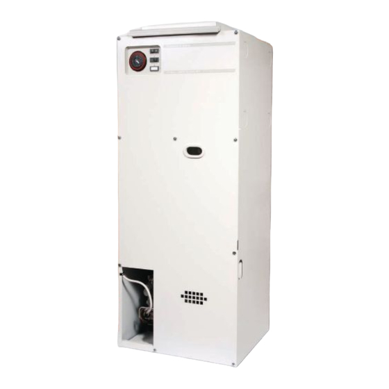
BRIEF DESCRIPTION
Fig. 1
THIS APPLIANCE CONFORMS TO BS EN 55014
G.C. No 42 451 08
1
2
12
7
8
9
1
Publication No. ZZ 810/6
1
Air Filter
2
Air circulating fan
3
Heat exchanger access cover
4
Data plate
5
Electrical Panel Assembly
6
Multifunctional control
7
Fan delay control/limit switch
8
Viewing port
9
Pilot Burner
10
Burner Assembly
11
Gas supply pipe
12
Piezo igniter unit
December 2005
Advertisement
Table of Contents

Subscribe to Our Youtube Channel
Related Manuals for Johnson & Starley HI-SPEC J25RS Series


Summary of Contents for Johnson & Starley HI-SPEC J25RS Series
- Page 1 These instructions are to be left with the User or adjacent to the Gas Meter HI-SPEC J25RS SERIES WARM AIR HEATERS SYSTEM E-T and BASIC Control INSTALLATION, COMMISSIONING & SERVICING INSTRUCTIONS G.C. No 42 451 08 Publication No. ZZ 810/6 December 2005 This appliance has been tested and certified by B G Technology for use with natural gas G20.
-
Page 2: Ventilation And Combustion Air
Installation shall be in accordance with the current editions of:- Building Standards (Scotland) (Consolidation) Regulations Building Regulations Gas Safety (Installation and Use) Regulations (as amended) BS7671 Institute of Electrical Engineers (I.E.E.) Wiring Regulations BS6891 Installation of Low Pressure Gas Pipework of up to 28mm (R1) in domestic premises (2nd family gases). BS5440 Pt.1 (Flues for Gas Appliances) BS5440 Pt.2 (Air Supply for Gas Appliances) BS5864 Installation of Gas Fired Ducted Air Heaters... -
Page 3: Installation
DUCT SYSTEM All ductwork MUST be mechanically secured and sealed with good quality ducting tape. RETURN AIR 4.1.1 Room-sealed appliances may be installed without return air ducting provided that the path between the return air grille and the appliance return air inlet is protected in such a manner that the required airflow will be maintained at all times. - Page 4 13mm (ref) 38mm 142mm Important 1 2 3 4 1 2 3 4 1 2 3 4 1 2 3 4 1 2 3 4 1 2 3 4 1 2 3 4 1 2 3 4 1 2 3 4 1 2 3 4 Flue outlet Eye bolt...
- Page 5 METHOD OF FIXING 5.4.1 Due to base plan variations between the replacement and the original heaters, at some stage it may be necessary to blank off part or parts of the base duct aperture. This can be done at the discretion of the installer, but it is important that a suitable non-combustible material is used and that the perimeter of the remaining aperture is bounded by suitable sealing tape to ensure a good seal between the heater and the base duct.
- Page 6 COMMISSIONING PREPARATION: 6.1.1 Ensure that: Gas and Electrical supplies are OFF. Filter, fan and fan compartments are free from obstructions. All registers or grilles are open and conform to design specifications. Return, relief and ventilation air installations are adequate. SETTING OF FAN SPEED: 6.2.1 Remove the air filter and fan chamber door.
- Page 7 1. Operating control 2. Burner Pressure Adjuster 3. Outlet Pressure test point Fig. 4 Multifunctional Control MAIN BURNER PRESSURE TEST: NOTE: AIR HEATER BURNERS ARE FACTORY SET TO PROVIDE A NOMINAL HIGH PRESSURE OUTPUT AS DETAILED IN SUB PARA 1.2 6.4.1 Referring to Table 2 and Fig.
-
Page 8: Safety Checks
BASIC Control heaters, the fan speed is adjusted by selecting the fan speed at control panel (decrease voltage selection to decrease fan speed). AUTOMATIC CONTROLS CHECK 6.7.1 Ignite the Pilot and Main burners and allow to operate for 15 minutes to ensure stability. 6.7.2 Set the TIME CONTROL (if fitted) to ‘ON’. -
Page 9: Air Volume
LOW RATE HIGH RATE MJ/h Btu/h MJ/h Btu/h INPUT 9.01 32.45 30,750 10.22 36.8 34,880 OUTPUT 6.44 23.21 22,000 7.33 26.38 25,000 Gas rate cv 0.80m /h (28.3ft 0.9m /h (31.9ft 1037Btu/ft Burner setting 11.5mbar (4.6 in wg) 15.2mbar (6.1 in wg) pressure (hot) Main Injector BRAY CAT 960/480. -
Page 10: Routine Maintenance
MAINTENANCE IMPORTANT: Ensure gas and electricity supplies are isolated before commencing any maintenance or replacement of components. After completion of any maintenance, always test for gas soundness and carry out a complete functional test of the appliance in accordance with Commissioning Instructions at Sect 6.1 to 6.8 inclusive. - Page 11 PILOT BURNER ASSEMBLY REMOVAL: 8.5.1 Remove Burner and Controls assembly as detailed in 8.2. 8.5.2 Disconnect the pilot gas feed pipe from the Multifunctional control and Pilot Assembly. 8.5.3 Disconnect the thermocouple from the Multifunctional control, taking care to avoid damage to the capillary. 8.5.4 Release the 4 x screws securing the Pilot Assembly to the Burner and Controls assembly, and withdraw the Pilot Assembly.
- Page 12 BASIC Control models: 8.9.4 Disconnect the following: Air circulation fan flying leads from the Fan assembly, 230V mains ‘L’, ‘N’ and ‘E’ from connection block terminals ‘1’ and ‘2’, and Earth stud respectively, Room thermostat connections from connection block terminals ‘7’ and ‘8’, Limit switch from connection block terminals ‘13’...
-
Page 13: Defect Diagnosis
8.14 HEAT EXCHANGER ACCESS: 8.14.1 Ensure that the electrical supply is isolated. 8.14.2 Remove the appliance front door. 8.13.3 Remove the Fan Delay Control/Limit switch wiring loom clip from the return edge of the fan chamber floor. 8.13.4 Release the 6 screws securing the access plate to the bulkhead, and withdraw the access plate and gasket. 8.13.5 Release the 8 screws securing the top access cover plate, and withdraw the cover plate and gasket. - Page 14 Main burner opera- i. Gas rate or burner pressure Check gas rate and burner pressure ting intermittently setting high. setting. with fan running. ii. Temperature rise excessive. Adjust fan speed or gas rate accordingly. iii. Air filter or return air path Check filter is clean and air path is clear.
- Page 15 SYSTEM E-T DEFECT DIAGNOSIS FLOW CHART MAIN BURNER NOT OPERATING TURN GAS PILOT LIT ? ON ? IS 230V LIGHT SWITCH ON SUPPLY PILOT 230 V ON ? IS TIME CONTROL & SET CONTROLS THERMISTA-STAT CORRECTLY CORRECTLY SET ? DISCONNECT THERMISTA-STAT AT TERMINALS ‘7’...
- Page 16 FAN OPERATES, BUT BURNER CYCLES BEFORE REQUIRED TEMPERATURE IS REACHED DISCONNECT THERMISTA-STAT AT TERMINALS ‘7’ & ‘8’, LINK TERMINALS ‘7’ & ‘TEST’ DO NOT LINK ‘7’ &’8’ DOES THE BURNER REPLACE CONTINUE TO THERMISTA-STAT CYCLE? CHECK RETURN AIR PATH FOR RESTRICTIONS DOES THE BURNER CONTINUE TO...
- Page 17 FAN RUNS BUT MAIN BURNER NOT OPERATING ‘SUMMER SET ‘SUMMER AIRFLOW’ AIRFLOW SWITCH TO SWITCH ‘0’ SET TO ‘0’ THERMISTA CONNECT -STAT THERMISTA-STAT CONNECTED THERMISTA -STAT SET TO ‘SUMMER AIRFLOW SET THERMISTA-STAT TO REQUIRED TEMPERATURE SETTING DOES FAULT FAN STILL CLEARED RUN ? DISCONNECT THERMISTA-STAT...
- Page 18 MAIN BURNER NOT CYCLING ROOM TEMPERATURE TOO HIGH) DISCONNECT THERMISTA-STAT DOES REPLACE BURNER THERMISTA-STAT GO OUT? DISCONNECT MULTIFUNCTIONAL CONTROL AT TERMINAL 15 REPLACE DOES ELECTRONICS BURNER GO OUT? MODULE REPLACE MULTIFUNCTIONAL CONTROL FAN CONTINUES TO RUN, OR CYCLES AFTER HEATING IS TURNED OFF DISCONNECT TERMINALS ‘17’...
- Page 19 Fig. 6a, SYSTEM E-T FUNCTIONAL DIAGRAM...
- Page 20 Fig. 6b, BASIC CONTROL FUNCTIONAL DIAGRAM...
- Page 23 SIDE VIEW SPIGOT POSITION FRONT VIEW FROM FRONT TOP VIEW BASE VIEW Fig. 8, PRINCIPAL DIMENSIONS (mm)
-
Page 24: Short List Of Spares
SHORT LIST OF SPARES HI-SPEC J25RS G.C No MFR’S No DESCRIPTION 232 961 BOS 02064 Fan Assembly 245 508 R253-0145000 Filter Assembly 378 466 BOS 02031 Time Control 381 627 1000-0701140 Multifunctional Control 232 948 BOS 02061 ‘O’ Ring Seal 245 545 1000-0705000 Pilot Burner Assembly...
Need help?
Do you have a question about the HI-SPEC J25RS Series and is the answer not in the manual?
Questions and answers