Table of Contents
Advertisement
sustainable solutions under one roof
H E A T I N G
H O T W A T E R
V E N T I L A T I O N
Publication No. ZZ 0941-9
June 2016
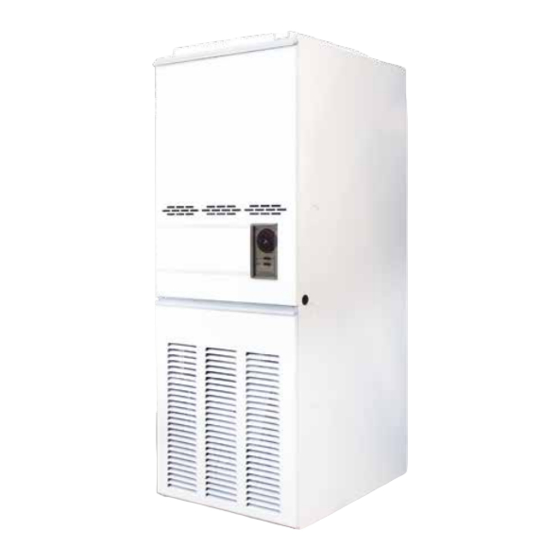
HI-SPEC J65
Warm Air Heater
with Modairflow or
Non Modairflow Control
INSTALLATION, COMMISSIONING
& SERVICING INSTRUCTIONS
Hi-Spec J65
-
G.C. No. 42-451-14
These instructions are to be left with the User
www.johnsonandstarley.co.uk
Advertisement
Table of Contents

Related Manuals for Johnson & Starley HI-SPEC J65


Summary of Contents for Johnson & Starley HI-SPEC J65
- Page 1 H E A T I N G H O T W A T E R V E N T I L A T I O N Publication No. ZZ 0941-9 June 2016 HI-SPEC J65 Warm Air Heater with Modairflow or Non Modairflow Control INSTALLATION, COMMISSIONING &...
-
Page 2: Table Of Contents
CONTENTS The Benchmark Scheme Defect Diagnosis General Description 10 Fault Finding Heater Compartment & Clearances 11 Wiring Diagrams Ventilation & Combustion Air 12 Functional Diagrams 13 Dimensions Duct System Return Air 14 Notes Warm Delivered Air 15 Short List of Spares Installation Requirements Flues 16 Exploded Diagram... -
Page 3: General Description
(MODAIRFLOW) Fig. 1 HI-SPEC J65 is an open-flued, fan assisted downflow, ducted warm air heater, which may be supplied with MODAIR- FLOW control and in conjunction with an ELJAN 6 water circulator. A non-MODAIRFLOW version is available as an option. A Spillage Monitoring Device (TTB) is fitted which senses the temperature in the draught diverter, and shuts down Fig. -
Page 4: Heater Compartment & Clearances
IMPORTANT: STATUE LAW DEFINES THAT ALL GAS APPLIANCES MUST BE INSTALLED COMPETENT PERSONS, i.e. GAS SAFE REGISTERED INSTALLERS. GAS SAFE MEMBERSHIP ENQUIRIES TEL: 0800 408 5500 IN ACCORDANCE WITH THE GAS SAFETY (INSTALLATION AND USE) REGULATIONS (CURRENT EDITION). FAILURE TO COMPLY WITH THESE REGULATIONS MAY LEAD TO PROSECUTION. HEATER COMPARTMENT AND CLEARANCES (See BS 5864 IMPORTANT: If the heater is to be fitted to an existing base duct (warm air plenum), always ensure that installation is carried out such that the rear left hand corner of the heater is aligned with the rear left hand corner of the base duct, so... -
Page 5: Duct System
DUCT SYSTEM RETURN AIR 4.1.1 All return air shall be POSITIVELY ducted from outside the compartment to the top of the unit via a return air duct, and mechanically secured. It is recommended that the return air duct be not routed directly from the main living area, but from a convenient central area serving the remainder of the dwelling. -
Page 6: Installation Requirements
The base duct, which equalises the air pressure to supply ducts, shall be constructed to support the weight of the heater, which shall be secured to the plenum with screws on at least two sides, and sealed using self-adhesive foam strip, ducting tape or sealing compound. All ducting and blanking plates shall be mechanically secured and sealed. - Page 7 Table 2 gives resistance factors for common flue components for use in the formula. Table 3 contains the appropriate inlet and outlet flue resistances. (the flue is likely to be satisfactory if its equivalent height exceeds 1m). Component Internal Size Resistance Component Internal Size...
- Page 8 STET Terminal 2 x 300 mm lengths 100 mm dia flue pipe = 6.2m 4.6m 4 x 1000 mm lengths bend 300 mm length 1.6m bend 2 x 300 mm lengths Appliance draught Fig. 2 diverter Worked example of equivalent flue height 5.1.12 Special consideration must be given to external flues with a view to prevention of condensation and weathering problems.
-
Page 9: Electrical
diverter Fig. 2 Worked example of equivalent flue height ELECTRICAL 5.2.1 Mains. The heater is supplied with mains cable (PVC sheathed, heat resisting to 85 C), 3-core Brown-Blue- Green/Yellow, 6A, 0.75mm ), connected to a terminal block and exiting through the heater at the right hand top front. -
Page 10: Commissioning
servicing. The gas pipe should be so fitted and installed as to be durable, substantial and gas tight. To assist in determining where a gas connection may not be tight, a leak detection fluid should be applied around the connection. Under no circumstances should a flame be used to locate a gas leak. Gas entry to the air heater is through either side to a Rc1/2 (1/2in BSP. -
Page 11: Temperature Rise Check
Fig. 3 PILOT BURNER ASSEMBLY MAIN BURNER PRESSURE TEST: NOTE: AIR HEATER BURNERS ARE FACTORY SET TO PROVIDE A NOMINAL HIGH RATE OUTPUT AS DETAILED IN SUB PARA 1.2 6.4.1 Referring to Table 4 and Fig. 4 below, ensure that the pressure test gauge indicates the correct burner pressure, resetting if required as follows: At the Multifunctional Control: Remove the Burner Pressure Adjuster cover. -
Page 12: Safety Check
6.7.5 When the temperature reaches the control setting, check that the Main Burner cycles ON and OFF, at approximately 75 to 120 seconds. Non-MODAIRFLOW models: 6.7.6 When the temperature reaches the control setting, ensure that the Main Burner extinguishes followed by the fan switching off after a short period. -
Page 13: Instructions For User
Table 4 Main Burner Pressure Settings mbar in.wg. 0.50 0.20 RESPONSE AREA 0.375 0.15 0.25 0.10 0.125 0.05 800 ft /min 0.14 0.19 0.24 0.28 0.33 0.38 m /sec AIR VOLUME Table 5 Fan Performance Curve INSTRUCTIONS FOR USERS If the building is unoccupied, ensure that the Instructions for User are left taped to the air heater for the User, and Installation Instructions are left at or near the air heater for use on future service calls. -
Page 14: Maintenance
the building must not be obstructed. 7.2.8 That the heater must be serviced at least once a year by a competent person to ensure efficient and safe operation. 7.2.9 That the red instructions for safe use have been pointed out and understood. 7.2.10 That expert help must be obtained if persistent failure of the pilot burner occurs. - Page 15 8.5.1 Remove the Burner and Controls Assembly as detailed in 8.2 8.5.2 Disconnect the Igniter lead from the Piezo unit. 8.5.3 Disconnect the Thermocouple from the Thermocouple adapter on the Multifunctional Control, taking care to avoid damage to the thermocouple capillary. 8.5.4 Release the Pilot Feed Pipe from the Multifunctional Control.
- Page 16 8.9.6 Disconnect the following: Disconnect 230V connections (L/N/E) from Fan Assembly, 230V mains ‘L’, ‘N’ and ‘E’ from connection block terminals ‘1’ and ‘3’, and earth stud respectively, Room thermostat from connection block terminals ‘5’ and ‘6’, Limit switch ‘LOAD’ and ‘COMMON’ connections, Fan Delay Control ‘LOAD’, ‘COMMON’...
- Page 17 8.14.7 Whilst holding the TTB Access Panel, release the 2 x securing screws and withdraw the TTB access panel. 8.14.8 Release the screw securing the TTB bracket assembly, and withdraw the bracket assembly. 8.14.9 Release the 2 x M4 screws securing the TTB Bracket to the TTB Assembly and withdraw the Bracket 8.14.10 Disconnect the TTB from its conductors.
- Page 18 8.15.6 Remove the Heat Exchanger baffles. 8.15.7 Reassembly is in reverse order. NOTE: When reassembling, ensure that the baffle is pushed fully home and that the access cap is fully sealed. In the event of heat exchanger replacement being necessary, contact Johnson and Starley Service Department. 9.
- Page 19 Main burner operating i. Gas rate or burner pressure Check gas rate and burner pressure with intermittent setting too low. setting. fan operation. ii. Fan Delay Control set incorrectly. Check for correct settings. Fan runs for excessive i. Fan Delay Control set incorrectly. Check for correct settings.
- Page 20 MODAIRFLOW DEFECT DIAGNOSIS FLOW CHART 10. FAULT FINDING MODAIRFLOW FAULT FINDING MAIN BURNER ON, BUT FAN NOT RUNNING CHECK FOR VOLT- REPLACE FAN AT FAN LIVE TO NEUTRAL BRIDGE OUT AIRFLOW SENSOR DOES REPLACE AIRFLOW SENSOR START? REPLACE CHECK FOR VOLTAGE AT ELECTRONICS FAN LIVE TO EARTH MODULE...
- Page 21 MAIN BURNER NOT OPERATING TURN GAS PILOT LIT ? ON ? IS 230V LIGHT SWITCH ON SUPPLY PILOT 230 V ON ? IS TIME CONTROL & SET CONTROLS THERMISTA-STAT CORRECTLY CORRECTLY SET ? REPLACE FUSE FUSE OK ? CHECK 24V AT REPLACE MULTIFUNC- MULTIFUNCTIONAL...
- Page 22 FAN OPERATES, BUT BURNER CYCLES BEFORE REQUIRED TEMPERATURE IS REACHED BRIDGE THERMISTA-STAT DOES REPLACE BURNER THERMISTA-STAT STAY LIT? REPLACE OVERHEAT CONTROL ELECTRONIC MODULE OK ? CHECK TEMPERATURE CHECK TTB, LIMIT RISE ACROSS HEATER IS SWITCH & CONNECTIONS LESS THAN 60°C CHECK AIR FILTER &...
- Page 23 MAIN BURNER ONLY FIRES FOR SHORT PERIODS THERMISTA- SET THERMISTA-STAT STAT TO MAX SET TO MAX ? BRIDGE THERMISTA-STAT AT HEATER DOES REPLACE BURNER ELECTRONIC MODULE STAY LIT? CHECK THERMISTA-STAT FAN CONTINUES TO RUN AFTER HEATING IS TURNED OFF CONNECTIONS POLARITIES FAN CONTINUES TO RUN AFTER HEATING IS TURNED OFF CHECK FAN SELECTOR SWITCH SETTING...
- Page 24 11. WIRING DIAGRAMS www.johnsonandstarley.co.uk...
- Page 25 Sales/Spares & Replacement Help Line 01604 762881...
- Page 26 12. FUNCTIONAL DIAGRAMS Fig 6a. Non-MODAIRFLOW FUNCTIONAL DIAGRAM www.johnsonandstarley.co.uk...
- Page 27 Fig 6b. MODAIRFLOW FUNCTIONAL DIAGRAM Sales/Spares & Replacement Help Line 01604 762881...
- Page 28 13. DIMENSIONS Fig 7. HI-SPEC J65 DIMENSIONS www.johnsonandstarley.co.uk...
- Page 29 14. NOTES Sales/Spares & Replacement Help Line 01604 762881...
- Page 30 SHORT LIST OF SPARES 15. SHORT LIST OF SPARES ITEM G.C. MAKER’S DESCRIPTION ITEM G.C MAKER’S DESCRIPTION 245-176 J650-0525000 Fan assembly E02-430 J652-0182000 Filter tray assembly 244 985 CL3S Time control CL3 244 986 1000-0000040 Time control cover 384 739 BOS00105 Limit Switch Honeywell L4069C...
- Page 31 EXPLODED DIAGRAM Fig 8. HI-SPEC J65 EXPLODED DIAGRAM Sales/Spares & Replacement Help Line 01604 762881...
- Page 32 British Standard BS 5864 by following the guidance in the HEATING COMPLIANCE GUIDE and the For further information contact Johnson & Starley Ltd on Telephone: 01604 762881 HI-SPEC J65 ANCILLARIES ITEMS DESCRIPTION PART No. Base Tray BT 65 Base Duct...
- Page 33 Code Of Practice For the installation, commissioning and servicing of domestic heating and hot water products Benchmark places responsibilities on Standards of Work both manufacturers and installers.* • Be competent and qualified to undertake the work required. The purpose is to ensure that •...
- Page 34 WARM AIR HEATER AND CIRCULATOR COMMISSIONING CHECKLIST This Commissioning Checklist is to be completed in full by the competent person who commissioned the warm air unit and associated equipment as a means of demonstrating compliance with the appropriate Building Regulations and then handed to the customer to keep for future reference.
- Page 35 SERVICE RECORD It is recommended that your heating system is serviced regularly and that the appropriate Service Interval Record is completed. Service Provider Before completing the appropriate Service Record below, please ensure you have carried out the service as described in the manufacturer’s instructions. Always use the manufacturer’s specifi ed spare part when replacing controls.
- Page 36 Johnson & Starley Ltd Rhosili Road, Brackmills, Northampton NN4 7LZ sales@johnsonandstarley.co.uk marketing@johnsonandstarley.co.uk Reception/Customer Service 01604 762881 01604 767408 Anniversary 1922 - 2012 In the interest of continuous development Johnson & Starley reserve the right to change specifications without prior notice.
Need help?
Do you have a question about the HI-SPEC J65 and is the answer not in the manual?
Questions and answers