Advertisement
Quick Links
Maintenance requirements
The SM700 series of cold water meters typically
do not require routine maintenance. The water meter
is powered by a 3.6 volt battery. Low battery power
is indicated by the display digits flashing on and off,
at which stage the meter should be replaced. This
should be undertaken within three months.
The SM700 series of cold water meter features
a removable battery pack to allow for disposal
separately to the rest of the meter. For battery pack
removal instructions, please refer to the separate
instructions numbered D-1001-1.
Note: The batteries used in this meter are potentially
hazardous if damaged. Battery disposal should be
undertaken with consideration to any requirements
by law for the disposal of Lithium-thionyl
chloride batteries.
Health & Safety information
In installations where the pipework is part of an
electrical earthing circuit the inlet and outlet pipes
must be connected by a permanently bonded
electrical earth grounding strap.
Note: The battery carries a warning as follows:- Fire,
explosion and severe burn hazard. Do not crush,
recharge, disassemble, heat above 212°F (100°C) or
incinerate. Do not short-circuit.
Contact Information:
United States
Elster AMCO Water, LLC
10 SW 49th Avenue, Building 100
Ocala, FL 34474
T +1 800 874 0890
F +1 352 368 1950
watermeters@us.elster.com
www.elsteramcowater.com
Note: Only products
bearing the NSF Mark
are certified.
Certified to
NSF/ANSI 61
Due to our policy of continual improvement
we reserve the right to change the specification
without prior notice.
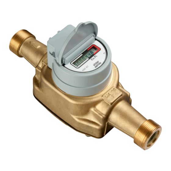
This document covers
the SM700 series
Introduction
The SM700 series of cold water meters
are designed to conform to AWWA C700/
C713 specification. The meters are rated at
150psi (10 bar). The meter designation is
indicated on the display facia and the case.
Air or air/water mixtures will typically
have no damaging effect on the internal
components of the meter and air flow
through the meter will not be registered.
Installation instructions
1. Remove the two plastic thread protection caps before
installation.
2. The meter must be installed with the arrow pointing
in the direction of the water flow.
3. Cut the pipework to the correct size (see Table 1 for
lay length). This is important to prevent tensile loading
across the meter when tightening.
4. Ensure that the pipework is aligned correctly prior to
installation of the meter. Do not use the meter as a
lever to align the pipework in any manner.
5. Ensure that the pipes are flushed and sealing faces
are free from debris and contamination.
6. Fit the meter to the service pipework in accordance
with standard installation practice.
7. Ensure that rubber or fibre sealing washers are fitted
between the pipe and water meter connections.
Where washers are supplied with the meter, these
must be used. Do not use P.T.F.E tape or sealing
paste to provide a water tight seal.
8. Locate the nuts on the pipework onto the meter
threads and screw on finger tight. Care should
be taken to prevent cross threading or stripping of
threads when making the connection.
9. Tighten the nut a further quarter to half a turn
using a wrench. Typical torque 11 ft-lbs min.
to 14.75 ft-lbs max. (15Nm min. to 20Nm max.).
Do not over tighten.
10. If the meter is connected do not solder or make any
solder joints within 8 inches of the meter. If soldering is
undertaken, aim torch away from meter at all times.
11. Ensure the pipework is securely fixed to avoid
vibration or bending across the meter.
Handling and Storage
The meter should be handled with care and
must not be dropped or subjected to impact.
It is recommended the meter be stored
under controlled conditions, preferably at a
temperature between 15°F (–10°C) & 105°F
(+40°C) and kept away from direct sunlight.
The meter should remain boxed, with the
two plastic thread protection caps in place,
until the point of installation. Do not carry
the water meter by the attached cable.
Fitting should be undertaken by
a competent trained installer.
These instructions should be
read and understood before
commencing the installation.
12. The meter should be installed away from sources
of heat and out of direct sunlight.
13. The meter installation should be protected
from freezing.
14. The meter can be fitted to horizontal, vertical or
inclined pipework.
15. When water has been turned on check all joints
for signs of leakage.
16. It is recommended to thoroughly purge the entire
water system, including all valves and pumps, of
air prior to recording any reading as required by
the utility.
17. For connection to a remote reading system, see
the manufacturer's instructions and refer to table 2
of these instructions for wire color assignments
when required.
Note: Do not install the communications cable along or
within 6 inches of existing cable runs.
Reading the meter
The reading is displayed on the totalizer module of the
meter under a protective lid. The display digits before
the decimal point, surrounded by a black or both a
black and white border on the facia, represent whole
US gallons (gal.), cubic feet (ft
3
) or cubic meters (m
and the digits after the decimal point, surrounded by
a red border, represent fractions of a gallon, ft
3
When water is flowing a flashing square icon appears
to the lower right of the display, but when the flow has
stopped this indicator will be extinguished.
To read the meter using a remote reading system,
refer to the manufacturer's instructions.
3
)
or m
.
3
Advertisement

Related Manuals for Elster SM700 Series


Summary of Contents for Elster SM700 Series
- Page 1 This is important to prevent tensile loading 15. When water has been turned on check all joints United States The SM700 series of cold water meters typically across the meter when tightening. for signs of leakage. do not require routine maintenance. The water meter Elster AMCO Water, LLC 4.
- Page 2 Table 1 Figure 1 Figure 2 Figure 3 Figure 4 Straight Pipe AWWA Meter Connection Meter Size Length Thread 5/8” x 1/2” 7 1/2” 3/4” 5/8” x 3/4” 7 1/2” 1” 3/4” x 3/4" 7 1/2” 1” 3/4” x 3/4" 9”...
Need help?
Do you have a question about the SM700 Series and is the answer not in the manual?
Questions and answers