Advertisement
S100
Commissioning Instructions
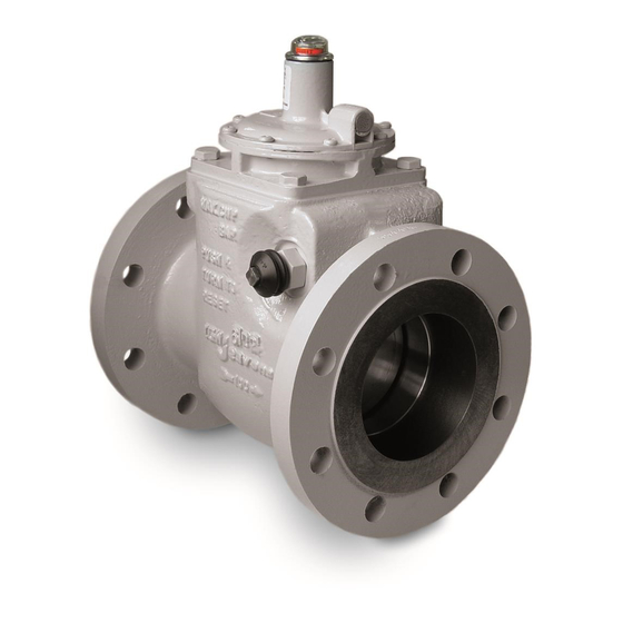
Impulse Sense
Connection
Fig. 1
Fig. 2
INSTALLATION CONDITIONS
Body pressure range: 0 - 19 Bar
(0 – 16 Bar for units with flanges to BS EN 1092-2 NP16)
Temperature range: -20ºC to +80 ºC
Vent
OPERATING INSTRUCTIONS
Connection
•
Ensure that this product is suitable for the chosen application.
•
Installation, adjustment and maintenance by authorised, trained personnel only.
•
When being fitted to an appliance, refer to the appliance manufacturers instructions.
•
Ensure that the installation provides adequate protection to prevent over
pressurisation.
•
Traffic, wind and earthquake loadings should be considered when specifying the
installation.
•
The unit should be protected from the decomposition of unstable fluids.
Warning!
cause injury or damage.
Read the instructions before use. This control must be installed in accordance with the rules in
force.
FITTING UNITS INTO PIPEWORK. Fig. 1
1.
The unit should not be installed in a corrosive environment.
2. The ambient temperature (surface temperature) should be within the limits
stated on the slam shut valve catalogue.
3. Check the maximum allowable pressure on the slam shut valve nameplate
against the installation specification.
4. Remove protective discs from flanges on inlet and outlet ports.
5. Ensure installation pipework is thoroughly clean.
6. The direction of gas flow must be the same as the arrows on the slam shut
body.
7.
Install the slam shut valve into the pipework, using gaskets and bolting
approved to National Standards.
8. Connect impulse line to sense chamber tapping, using jointing compound
approved to National Standards.
b
9. Vent line can be installed as below if required:
10. Remove vent protective screen and connect vent pipe line to top cover, using
a
jointing compound approved to National Standards.
11. Lead pipe to atmosphere in accordance with National Standards.
VALVE OPERATION (Fig 2)
As the sense pressure rises to the desired trip point, it acts against the pressure
sensing diaphragm and pressure setting spring.
A bearing cage is lifted, allowing ball bearings to move radially outwards
against the bearing cage taper, to a point where the shoulder diameter on the
spring loaded shaft, is free to pass through the bearings (TRIP POINT).
As the shaft moves through the bearings, it releases the spring clip (a) thereby
allowing the valve seat assembly to operate in the closed position.
A valve position indicator (b) indicates that the valve has moved to the closed
position.
Incorrect installation, adjustment, modification, operation and maintenance may
Advertisement
Table of Contents

Related Manuals for Elster S100


Summary of Contents for Elster S100
- Page 1 S100 Commissioning Instructions INSTALLATION CONDITIONS Body pressure range: 0 - 19 Bar (0 – 16 Bar for units with flanges to BS EN 1092-2 NP16) Temperature range: -20ºC to +80 ºC Impulse Sense Vent OPERATING INSTRUCTIONS Connection Connection • Ensure that this product is suitable for the chosen application.
- Page 2 S100: Commissioning Instructions SETTING THE TRIP PRESSURE (Fig 3) Ensure valve is depressurized. 2. Remove cap, spring and indicator. 3. Screw adjusting nut clockwise as far as it will go, Do Not Force. 4. Induce desired set pressure at pressure sense point.
Need help?
Do you have a question about the S100 and is the answer not in the manual?
Questions and answers