Advertisement
Quick Links
S e n s o r P u c k
S
P
U
'
G
ENSOR
U C K
SER
S
UIDE
1. Introduction
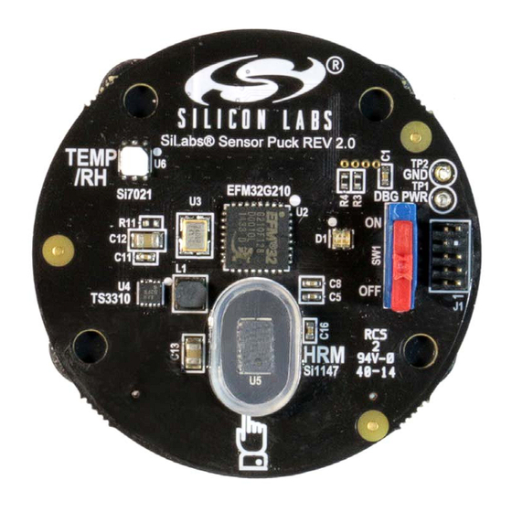
The sensor puck demonstrates Silicon Laboratories optical sensor (Si1147-M01) RH and temperature sensor
(Si7021) and low power MCU (EFM32G210 "Gecko"). The data is broadcast using a Bluetooth Low Energy (BLE)
module and can be displayed on a mobile device (Apple iOS or Android) that supports the BLE protocol.
By using broadcast mode, a connection does not have to be established, making it possible to display the data
from several modules at the same time.
2. Evaluation Kit Description
Figure 1. Silicon Labs Sensor Puck
The evaluation kit consists of a sensor puck with a battery and the on/off switch in the off position. Install the battery
if it is not installed. The + terminal of the battery faces away from the board towards the + terminal of the battery
holder. Remove the pull tab separating the battery from the battery holder if needed. When the switch is turned on,
the puck will automatically start taking and broadcasting data. For the puck itself, there is no installation required.
Rev. 1.0 2/15
Copyright © 2015 by Silicon Laboratories
Sensor Puck
Advertisement

Related Manuals for Silicon Laboratories SENSOR PUCK


Summary of Contents for Silicon Laboratories SENSOR PUCK
- Page 1 Figure 1. Silicon Labs Sensor Puck The evaluation kit consists of a sensor puck with a battery and the on/off switch in the off position. Install the battery if it is not installed. The + terminal of the battery faces away from the board towards the + terminal of the battery holder.
-
Page 2: Operation
The data that is broadcast is generally displayed on a mobile device. To display the data the Silicon Labs Sensor Puck app must be installed on the mobile device. The application is available for no charge from the Apple App Store or the Google Play Store. (Search for Silicon Labs Sensor Puck.) 3. Operation ... -
Page 3: Sensor Puck Applications
“Silicon Labs Sensor Puck”. The iOS Sensor Puck app can be installed from the Apple App Store. The iOS app runs on devices with iOS 7 and higher, and has Bluetooth 4.0 hardware. Silicon Labs has verified that the iOS app runs on iPhone 4S, 5, 5S, 6 and 6 Plus. - Page 4 The temperature scale can be changed between Celsius and Fahrenheit by tapping the small C and F buttons. When the puck is in biometric mode, the Android Sensor Puck displays the biometric screen. Figure 3. Android Biometric Screen...
- Page 5 S en so r P u ck The iOS Sensor Puck app does not have a biometric screen. The iOS app displays the heart rate in the lower right corner of the environmental screen: Figure 4. iOS Environmental Screen Rev. 1.0...
- Page 6 S en so r P u c k If there are several sensor pucks, you can use the navigation drawer to select a different puck. To open the navigation drawer, tap on the three-line icon in the upper left corner of the screen or swipe from the left edge of the screen.
- Page 7 S en so r P u ck You can change the name of a puck by tapping on the edit icon to the right of the puck name. Figure 6. Puck Name Rev. 1.0...
-
Page 8: Sensor Puck Hardware Description
S en so r P u c k 5. Sensor Puck Hardware Description 5.1. Schematics Figure 7 shows the block diagram of the puck with debug header MCU, the sensors, and the Bluetooth module. Pulse VMCU 04-RHT 03-Pulse LEDs HEADER 2x5/SM... - Page 9 S en so r P u ck VMCU VMCU Connect together then connect tp power plane Connect together then connect tp power plane 10uF 1.0uF VMCU EFM32G210 PE13 BLE_RESET PE12 BLE_WAKE PE11 PE10 DBG_SWO GREEN SWO PF2 DBG_SWDIO SWDIO PF1 DBG_SWCLK SWCLK PF0 PC15...
- Page 10 HOST UART_RX BLE_WAKE WAKE MODULE HOST_WAKE 598-8410-207CF WAKE HOST TPV6 RESET Figure 11. BLE Module and LEDs 5.2. Bill of Materials Table 1. Sensor Puck BOM Quantity Reference Value Voltage Manufacturer Manufacturer Part Number 1 BH1 20 mm BATTERY BAT-HLD-001...
- Page 11 S en so r P u ck Table 1. Sensor Puck BOM (Continued) Quantity Reference Value Voltage Manufacturer Manufacturer Part Number 1 R11 ±1% CR0402-16W- Venkel 47R0F 2 R13,R14 ±1% CR0402-16W- Venkel 2001F 4 SF4,SF5,SF6,SF7 BUMPER SJ61A6 1 SW1 SW_SLIDE_2POS NK236H Apem Inc.
-
Page 12: Sensor Puck Firmware
Install and launch the latest version of Simplicity Studio (www.silabs.com/simplicity). Connect the 20-pin header of the programming/debug cable to the EFM32 development kit. Connect the 9-pin header of the programming debug cable to the Sensor Puck. Slide Sensor Puck power switch to ‘ON’. ... - Page 13 Simplicity Studio. The details of doing this are beyond the scope of this document. Note: Sensor Puck is planned to be supported in V3.0 of Simplicity Studio. Prior to V3.0, the source code will be provided at www.silabs.com/sensor-puck.
- Page 14 The products are not designed or authorized to be used within any Life Support System without the specific written consent of Silicon Laboratories. A "Life Support System" is any product or system intended to support or sustain life and/or health, which, if it fails, can be reasonably expected to result in significant personal injury or death.
- Page 15 Mouser Electronics Authorized Distributor Click to View Pricing, Inventory, Delivery & Lifecycle Information: Silicon Laboratories SENSOR-PUCK...
Need help?
Do you have a question about the SENSOR PUCK and is the answer not in the manual?
Questions and answers