
Related Manuals for LG G3F-TC4A


Summary of Contents for LG G3F-TC4A
- Page 1 User User User User’ ’ ’ ’ s Manual s Manual s Manual s Manual LG Programmable Logic Controller GLOFA G3F – TC4A G4F – TC2A MASTER-K G6F – TC2A LG Industrial Systems...
- Page 2 REVISIONS Date REV. No Description 2001.4. 702004908 G6F-TC2A Module added...
- Page 3 Be sure to read carefully the safety precautions given in data sheet and user’s manual before operating the module and follow them. The precautions explained here only apply to the G3F-TC4A , G4F-TC2A andG6F-TC2A. For safety precautions on the PLC system, see the GLOFA GM3/4 User’s Manuals, GLOFA GM6 User’s Manuals or the MASTER-K 1000S/300S/200S User’s Manuals.
- Page 4 Installation Precautions Wiring Precautions CAUTION CAUTION ▶ Operate the PLC in the environ- ▶ When grounding a FG terminal, ment conditions given in the be sure to provide class 3 general specifications. grounding which is dedicated to ▶ If operated in other environment the PLC.
-
Page 5: Table Of Contents
1.2.7 Reference Junction Compensation (RJC) ∙∙∙∙∙∙∙∙∙∙∙∙∙∙∙∙∙∙∙∙∙∙∙∙∙∙∙∙∙∙∙∙∙∙∙∙∙∙∙∙∙∙∙∙∙∙∙∙∙∙∙∙∙∙∙∙∙∙∙∙∙∙∙∙∙∙ Chapter 2. SPECIFICATIONS 2.1 General Specifications ∙∙∙∙∙∙∙∙∙∙∙∙∙∙∙∙∙∙∙∙∙∙∙∙∙∙∙∙∙∙∙∙∙∙∙∙∙∙∙∙∙∙∙∙∙∙∙∙∙∙∙∙∙∙∙∙∙∙∙∙∙∙∙∙∙∙∙∙∙∙∙∙∙∙∙∙∙∙∙∙∙∙∙∙∙∙∙∙∙∙∙∙∙∙∙ 2.2 Performance Specifications ∙∙∙∙∙∙∙∙∙∙∙∙∙∙∙∙∙∙∙∙∙∙∙∙∙∙∙∙∙∙∙∙∙∙∙∙∙∙∙∙∙∙∙∙∙∙∙∙∙∙∙∙∙∙∙∙∙∙∙∙∙∙∙∙∙∙∙∙∙∙∙∙∙∙∙∙∙∙∙∙∙∙∙∙∙∙ 2.3 Names of Parts and Functions ∙∙∙∙∙∙∙∙∙∙∙∙∙∙∙∙∙∙∙∙∙∙∙∙∙∙∙∙∙∙∙∙∙∙∙∙∙∙∙∙∙∙∙∙∙∙∙∙∙∙∙∙∙∙∙∙∙∙∙∙∙∙∙∙∙∙∙∙∙∙∙∙∙∙∙∙∙∙∙∙∙∙∙∙∙ 2.3.1 G3F-TC4A ∙∙∙∙∙∙∙∙∙∙∙∙∙∙∙∙∙∙∙∙∙∙∙∙∙∙∙∙∙∙∙∙∙∙∙∙∙∙∙∙∙∙∙∙∙∙∙∙∙∙∙∙∙∙∙∙∙∙∙∙∙∙∙∙∙∙∙∙∙∙∙∙∙∙∙∙∙∙∙∙∙∙∙∙∙∙∙∙∙∙∙∙∙∙∙∙∙∙∙∙∙∙∙∙∙ 2.3.2 G4F-TC2A ∙∙∙∙∙∙∙∙∙∙∙∙∙∙∙∙∙∙∙∙∙∙∙∙∙∙∙∙∙∙∙∙∙∙∙∙∙∙∙∙∙∙∙∙∙∙∙∙∙∙∙∙∙∙∙∙∙∙∙∙∙∙∙∙∙∙∙∙∙∙∙∙∙∙∙∙∙∙∙∙∙∙∙∙∙∙∙∙∙∙∙∙∙∙∙∙∙∙∙∙∙∙∙∙∙∙∙ 2.3.3 G6F-TC2A ∙∙∙∙∙∙∙∙∙∙∙∙∙∙∙∙∙∙∙∙∙∙∙∙∙∙∙∙∙∙∙∙∙∙∙∙∙∙∙∙∙∙∙∙∙∙∙∙∙∙∙∙∙∙∙∙∙∙∙∙∙∙∙∙∙∙∙∙∙∙∙∙∙∙∙∙∙∙∙∙∙∙∙∙∙∙∙∙∙∙∙∙∙∙∙∙∙∙∙∙∙∙∙∙∙∙∙ 2.4 I/O Conversion Characteristics ∙∙∙∙∙∙∙∙∙∙∙∙∙∙∙∙∙∙∙∙∙∙∙∙∙∙∙∙∙∙∙∙∙∙∙∙∙∙∙∙∙∙∙∙∙∙∙∙∙∙∙∙∙∙∙∙∙∙∙∙∙∙∙∙∙∙∙∙∙∙∙∙∙∙∙∙∙∙∙∙∙∙∙∙ 2.4.1 Temperature Conversion Characteristics ∙∙∙∙∙∙∙∙∙∙∙∙∙∙∙∙∙∙∙∙∙∙∙∙∙∙∙∙∙∙∙∙∙∙∙∙∙∙∙∙∙∙∙∙∙∙∙∙∙∙∙∙∙∙∙∙∙∙∙∙∙∙∙∙∙∙∙... - Page 6 6.2.1 Specifying Channel Enable/Disable (G3F-TC4A : Address 0, G4F-TC2A/G6F-TC2A : Address 0) ∙∙∙∙∙∙∙∙∙∙∙∙∙∙∙∙∙∙∙∙∙∙∙∙∙∙∙∙∙∙∙∙∙∙∙∙∙∙∙∙∙∙ 6.2.2 Specifying the Type Of Thermocouple (G3F-TC4A : Address 1 To 16, G4F-TC2A G6F-TC2A : Address 1 to 4) ∙∙∙∙∙∙∙∙∙∙∙∙∙∙∙∙∙∙∙∙∙∙∙∙∙∙∙∙ 6.2.3 Temperature Conversion Value ∙∙∙∙∙∙∙∙∙∙∙∙∙∙∙∙∙∙∙∙∙∙∙∙∙∙∙∙∙∙∙∙∙∙∙∙∙∙∙∙∙∙∙∙∙∙∙∙∙∙∙∙∙∙∙∙∙∙∙∙∙∙∙∙∙∙∙∙∙∙∙∙∙∙∙∙∙∙∙ 6.2.4 Digital Conversion Value ∙∙∙∙∙∙∙∙∙∙∙∙∙∙∙∙∙∙∙∙∙∙∙∙∙∙∙∙∙∙∙∙∙∙∙∙∙∙∙∙∙∙∙∙∙∙∙∙∙∙∙∙∙∙∙∙∙∙∙∙∙∙∙∙∙∙∙∙∙∙∙∙∙∙∙∙∙∙∙∙∙∙∙∙∙∙∙...
- Page 7 6.2.7 Information on Run Channel (G3F-TC4A : Address 66, G4F-TC2A/G6F-TC2A : Address 18) ∙∙∙ 6.2.8 Information on Thermocouple Type Specification Error (G3F-TC4A : Address 67, G4F-TC2A /G6F-TC2A : Address 19) ∙∙∙∙∙∙∙∙∙∙∙∙∙∙∙∙∙∙∙∙∙∙∙∙∙∙∙∙∙∙∙∙∙∙∙∙ Chapter 7. DEDICATED INSTRUCTIONS FOR SPECIAL MODULES (Read from/Write to Buffer Memory) 7.1 Local...
- Page 8 10.3 G6F-TC2A Dimensions ∙∙∙∙∙∙∙∙∙∙∙∙∙∙∙∙∙∙∙∙∙∙∙∙∙∙∙∙∙∙∙∙∙∙∙∙∙∙∙∙∙∙∙∙∙∙∙∙∙∙∙∙∙∙∙∙∙∙∙∙∙∙∙∙∙∙∙∙∙∙∙∙∙∙∙∙∙∙∙∙∙∙∙∙∙∙∙∙ 10-3 ● Appendix APPENDIX 1 1.1 Thermoelectromotive Force Tables ∙∙∙∙∙∙∙∙∙∙∙∙∙∙∙∙∙∙∙∙∙∙∙∙∙∙∙∙∙∙∙∙∙∙∙∙∙∙∙∙∙∙∙∙∙∙∙∙∙∙∙∙∙∙∙∙∙∙∙∙∙∙∙∙∙∙∙∙∙∙∙∙∙∙∙∙∙ 1.2 Thermocouple ∙∙∙∙∙∙∙∙∙∙∙∙∙∙∙∙∙∙∙∙∙∙∙∙∙∙∙∙∙∙∙∙∙∙∙∙∙∙∙∙∙∙∙∙∙∙∙∙∙∙∙∙∙∙∙∙∙∙∙∙∙∙∙∙∙∙∙∙∙∙∙∙∙∙∙∙∙∙∙∙∙∙∙∙∙∙∙∙∙∙∙∙∙∙∙∙∙∙∙∙∙∙∙∙∙∙ 1.2.1 Normal and Overheat Temperature Limits ∙∙∙∙∙∙∙∙∙∙∙∙∙∙∙∙∙∙∙∙∙∙∙∙∙∙∙∙∙∙∙∙∙∙∙∙∙∙∙∙∙∙∙∙∙∙∙∙∙∙∙∙∙∙∙∙∙∙∙∙∙∙∙∙ 1.2.2 Temperature Tolerances ∙∙∙∙∙∙∙∙∙∙∙∙∙∙∙∙∙∙∙∙∙∙∙∙∙∙∙∙∙∙∙∙∙∙∙∙∙∙∙∙∙∙∙∙∙∙∙∙∙∙∙∙∙∙∙∙∙∙∙∙∙∙∙∙∙∙∙∙∙∙∙∙∙∙∙∙∙∙∙∙∙∙∙∙∙∙∙ 1.3 Compensating Wire ∙∙∙∙∙∙∙∙∙∙∙∙∙∙∙∙∙∙∙∙∙∙∙∙∙∙∙∙∙∙∙∙∙∙∙∙∙∙∙∙∙∙∙∙∙∙∙∙∙∙∙∙∙∙∙∙∙∙∙∙∙∙∙∙∙∙∙∙∙∙∙∙∙∙∙∙∙∙∙∙∙∙∙∙∙∙∙∙∙∙∙∙∙∙∙∙∙∙∙ 1.3.1 Types and Specifications of Compensating Wire ∙∙∙∙∙∙∙∙∙∙∙∙∙∙∙∙∙∙∙∙∙∙∙∙∙∙∙∙∙∙∙∙∙∙∙∙∙∙∙∙∙∙∙∙∙∙∙∙∙∙∙∙∙∙∙∙...
-
Page 9: Chapter 1. Introduction
Chapter 1. INTRODUCTION Chapter 1. INTRODUCTION This manual is a learning and reference guide for the G3F-TC4A , G4F-TC2A and G6F-TC2A. The G3F-TC4A is a thermocouple input module used with the CPU of GLOFA GM1/2/3 series and MASTER-K 1000S series .The G4F-TC2A is used with the CPU of GM4 series and K300S series The G6F-TC2A is used with the CPU of GM6 series and K200S series. -
Page 10: Glossary
Chapter 1. INTRODUCTION 1.2 Glossary 1.2.1 A - Analog Value time time [Fig.1.1] Analog Value [Fig.1.2] Digital Value Continuous changeable quantity such as voltage, current, temperature, velocity, pressures and flux is called an analog quantity. For example, temperature changes continuously with time as shown in Fig. 1.1. -
Page 11: Compensating Wire
Chapter 1. INTRODUCTION 1.2.3 Compensating Wire This means a wire used to compensate error (temperature change) by the distance between terminal of an input thermocouple and input terminal of a thermocouple input module. This has the thermoelectromotive force characteristics between the two terminals under the temperature of 90 to 150 °C or less. -
Page 12: Chapter 2. Specifications
Chapter 2 SPECIFICATIONS Chapter 2. SPECIFICATIONS 2.1 General Specifications Table 2.1 shows general specifications of the GLOFA GM series and MASTER-K series. Items Specifications Standard Operating ambient 0 ~ 55℃ temperature Storage ambient -25 ~ 70℃ temperature Operating ambient 5 ~ 95%RH, non-condensing humidity Storage ambient 5 ~ 95%RH,... -
Page 13: Performance Specifications
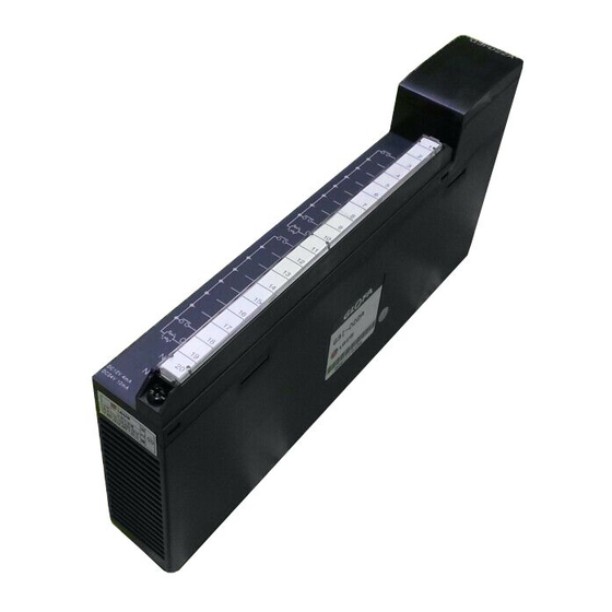
Chapter 2 SPECIFICATIONS 2.2 Performance Specifications Table 2.2 shows performance specifications of the thermocouple input module. Specifications Item G3F-TC4A G4F-TC2A G6F-TC2A Connectable Type K, J, E, T, B, R or S thermocouple thermocouple Digital conversion value : 0 to 16,000... - Page 14 Chapter 2 SPECIFICATIONS 2.3 Names of Parts and Functions The following gives names of parts : 2.3.1 G3F-TC4A The following gives the names and functions of each part of the G3F-TC4A. Contents RUN LED It displays the operating status of G3F-TC4A ①...
- Page 15 Chapter 2 SPECIFICATIONS 2.3.2 G4F-TC2A The following gives the names and functions of each part of the G4F-TC2A. ① Contents RUN LED It displays the operating status of G4F-TC2A ① : Normal Operation Flickering: Error occurred (For details, refer to Troubleshooting Sec- tion 9.1) ②...
-
Page 16: I/O Conversion Characteristics
Measuring cycle = 50 ms× (the number of conversion enabled channels) Example) When 10 channels are used in the G3F-TC4A Measuring cycle = 50 ms× 10 = 500 ms... -
Page 17: Accuracy
Chapter 2 SPECIFICATIONS 2.4.3 Accuracy The accuracy of the thermocouple input module is within ±0.3 % of all of the measuring tempera- ture range and error (±1°C) from reference junction compensation is added. Example) When a thermocouple type K is used, the detected temperature values to temperatures –200°C, 500°C and 1200°C are as below. -
Page 18: Displaying Temperature Conversion Value
Chapter 2 SPECIFICATIONS 2.4.5 Displaying Temperature Conversion Value The detected temperature value converted into through sampling processing of a thermocouple in- put value times by ten and that is displayed as a digital value, which is called temperature conver- sion value. [Example] When a real temperature is 100.5°C •... -
Page 19: Chapter 3. Installation And Wiring
Chapter 3. INSTALLATION AND WIRING Chapter 3. INSTALLATION AND WIRING 3.1 Installation 3.1.1 Installation Ambience This module has high reliability regardless of its installation ambience. But be sure to check the following for system in higher reliability and stability. 1) Ambience Requirements Avoid installing this module in locations, which are subjected or exposed to: - Water leakage and dust a large amount of dust, powder and other conductive power, oil mist, salt, of organic solvent exists. -
Page 20: Wiring
Chapter 3. INSTALLATION AND WIRING 3.2 Wiring 3.2.1 Wiring Precautions 1) Be sure to use compensating wire for sensor input wire and connect shield wire to the terminal FG and ground. 2) Be sure to separate the external input signal of the temperature conversion module from an alternating current so that surge or induction noise generated from the alternating current could not effect. -
Page 21: Chapter 4. Functions Blocks
Function blocks can be registered with the following procedure while the GMWIN is running. Insertion of the function blocks is only possible when a project is open. Project (P) Selection Library Insert (I) G3F-TC4A Inserting local 1. Special. 3fb function block • TC4INI •... -
Page 22: Local Function Block
- After the initialization function block is finished with no error, “1” is output if the *Note 1 channel is in normal state. But “0” is output for the disabled channels. REMARK ∗Note 1 [Array] : The numbers of Array are 16 in G3F-TC4A, 4 in G4F-TC2A/G6F-TC2A. 4 - 2... -
Page 23: Module Reading (Array Type) (G3F-Tc4A:tc4Ard, G4F- Tc2A/G6F-Tc2A:tc2Ard)
Minimum measuring temperature) temperature range - The output value through digital conversion can be used as a PV of the PID control module. REMARK ∗Note 1: The numbers of Array are 16 in G3F-TC4A, 4 in G4F-TC2A/G6F-TC2A 4 - 3... -
Page 24: Module Reading (Stand-Alone Type) (G3F-Tc4A : Tc4Rd, G4F-Tc2A/G6F-Tc2A:tc2Rd)
Chapter 4. FUNCTION BLOCKS 4.2.3 Module Reading (Stand-alone type) The stand-alone type module reading function block outputs the temperature conversion value to which each channel of the thermocouple input module is set to output variable TEMP. Function Data Variable Description Block Type Function block execution request area... -
Page 25: Module Initialization (G3F-Tc4A:tcr4Ini, G4F-Tc2A:tcr2Ini, G6F-Tc2A:tcr62Ini)
- After the initialization function block is finished without error, “1” is output [Array] if the channel is in normal state. But “0” is output for the disabled *Note 1 channels. REMARK *Note 1: The numbers of Array are 16 in G3F-TC4A, 4 in G4F-TC2A/G6F-TC2A 4 - 5... -
Page 26: Module Reading (Array Type)
Minimum measuring temperature) temperature range - The output value through digital conversion can be used as a PV of the PID control module. REMARK *Note 1: The numbers of Array are 16 in G3F-TC4A, 4 in G4F-TC2A/G6F-TC2A 4 - 6... -
Page 27: Errors Indicated During Execution Of Function Block
4.4.2 Errors indicated by the output variable, ALM_CODE in the array type temperature conversion value reading function block. (G3F-TC4A : TC4ARD, TCR4RD. G4F-TC2A : TC2ARD, TCR2RD G6F-TC2A : TC2ARD, TCR62RD) ALM_CODE No. Description Corrective Action ... -
Page 28: Chapter 5. Programming
Chapter 5. Programming Chapter 5. PROGRAMMING 5.1 A program for Converting a Detected Temperature Value(° ° ° ° C) into Fahrenheit(° ° ° ° F) and Outputting as a BCD Value 1) System Configuration Display the Fahrenh temperature value The lamp turns on if the Fahrenheit temperature value is negative. The lamp turns on if disconnection occurs % I0.0.0 The lamp turns on if the temperature conversion value is negative. - Page 29 Chapter 5. Programming 5) Program Indicating the error status during Indicating the error status during Base No. Base No. initialization function block execution reading function block execution. Indicating run channel during Turns on if error is detected at used Slot No. Slot No.
- Page 30 Chapter 5. Programming 6) Initial Value Setting Method for I/O Variables (1) Channel Specification Select this This denotes and this screen appears 16 channels Select this and this screen appears Selection of the previous channel Channel No. Selection of the next channel Channel enable : 1 Channel disable : 0...
- Page 31 Chapter 5. Programming (2) Thermocouple Type Specification Thermocouple type specification Input specification No. Sensor type Temperature range -200.0 to 1200.0°C -200.0 to 800.0°C -150.0 to 600.0°C -200.0 to 400.0°C 400.0 to 1800.0°C 0.0 to 1750.0 °C 0.0 to 1750.0°C 5 - 4...
- Page 32 Chapter 5. Programming 7) I/O Variables Used in the Program 5 - 5...
-
Page 33: A Program For Magnitude Comparison Of A Detected Temperature Value
Chapter 5. Programming 5.2 A program for Magnitude Comparison of a Detected Temperature Value 1) System Configuration 2) Initial Settings (1) Used Channel : Channel 0 and 1 (2) Thermocouple type specification : Type K 3) Program Descriptions (1) If the temperature that is input through the channel 0 of the thermocouple input module is less than -20°C or larger than –30 °C, %Q0.1.0 turns on. - Page 34 Chapter 5. Programming 4) Program Thermocouple input module initialization has been finished. Indicating the error status during Specifying mounted Base No. initialization function block execution Specifying mounted Slot No. Indicating run channel during initialization function block execution Specifying used channel Specifying Thermocouple type (type K) Channel 0 Reading complete.
- Page 35 Chapter 5. Programming 5) I/O Variables Used in the Program 5 - 8...
-
Page 36: A Program Used When Mounting A Thermocouple Input Module
Chapter 5. Programming A Program Used When Mounting a Thermocouple Input Module onto the Remote I/O Station 1) System Configuration Local Station No. ”0” Remote Station No. ”10” Thermocouple type K 2) Initial Settings (1) Specifying used channel : Channel 0 (2) Specifying thermocouple type: Type K 3) Program Description (1) _NET0_LIV[10] : Turns “On”... - Page 37 Chapter 5. Programming 4) Program Requests the execution of initialization function block so that the initialization can be executed one time when the opposite station is normally operating. Program for re-start after a power failure has occurred during communications. The opposite station power failure information If the power is restored from fault or power-off,...
- Page 38 Chapter 5. Programming 5) I/O Variables Used in the Program 5 - 11...
-
Page 39: Chapter 6. Buffer Memory Configuration And Functions
Chapter 6. BUFFER MEMORY CONFIGURATION AND FUNCTIONS The thermocouple-input module has the PLC CPU and the buffer memories for data communications. 6.1 Buffer Memory Configuration The followings describe buffer memory configuration. 6.1.1 G3F-TC4A Buffer Memory Function Description Channel enable/disable Specification... - Page 40 Chapter 6. BUFFER MEMORY CONFIGURATION AND FUNCTIONS Function Description Temperature conversion value of the channel 5 Digital conversion value of the channel 5 Error code of the channel 5 Temperature conversion value of the channel 6 Digital conversion value of the channel 6 Error code of the channel 6 Temperature conversion value of the channel 7 Digital conversion value of the channel 7...
-
Page 41: G4F-Tc2A/G6F-Tc2A Buffer Memory
Chapter 6. BUFFER MEMORY CONFIGURATION AND FUNCTIONS 6.1.2 G4F-TC2A / G6F-TC2A Buffer Memory Function Description Channel enable/disable Specification Bit On(1): Enable, Bit Off(0) : Disable Disable R/W Specifying the type of thermocouple for channel 0 Specifying the type of thermocouple for channel 1 -200.0 to 1200.0°C -200.0 to 800.0°C Type K R/W... -
Page 42: Buffer Memory Functions
Thermocouple type 4) Other value than the defined values is set for specifying the type of a thermocouple, the G3F-TC4A displays error code at the corresponding bit in the address 67 and the G4F-TC2A/G6F-TC2A in the address 19 with the type being specified to “0”, that is, type K thermocouple. -
Page 43: Temperature Conversion Value
Chapter 6. BUFFER MEMORY CONFIGURATION AND FUNCTIONS 6.2.3 Temperature Conversion Value 1) This area performs sampling processing of the temperature value that is inputted through the thermocouple connected to the terminal block of a channel and stores the value of 10 times of the real temperature value. -
Page 44: Error Code
0 to 16 in the G3F-TC4A and at the address 0 to 4 in the G4F-TC2A but with the previous setting data. If a bit0 corresponding to all channel in set data specification area is turned on(1),then the... -
Page 45: Information On Run Channel (G3F-Tc4A : Address 66, G4F-Tc2A/G6F-Tc2A : Address 18)
(G3F-TC4A : Address 67, G4F-TC2A/G6F-TC2A : Address 19) If other value than “0” to “6” is set at the addresses (Address 1 to 16 in G3F-TC4A, Address 1 to 4 in G4F-TC2A/G6F-TC2A) used for specifying the type of the thermocouple which is connected to each channel of the thermocouple input module, error occurs. -
Page 46: Local
Chapter 7. DEDICATED INSTRUCTIONS FOR SPECIAL MODULES Chapter 7. DEDICATED INSTRUCTIONS FOR SPECIAL MODULES (Read from /Write to Buffer Memory) The thermocouple input module occupies 16 I/O points. 7.1 Local 7.1.1 Read from Buffer Memory ⋅ ⋅ ⋅ ⋅ ⋅ ⋅ ⋅ ⋅ ⋅ ⋅ ⋅ ⋅ GET, GETP <Format>... - Page 47 Chapter 7. DEDICATED INSTRUCTIONS FOR SPECIAL MODULES Write to Buffer Memory ⋅ ⋅ ⋅ ⋅ ⋅ ⋅ ⋅ ⋅ ⋅ ⋅ ⋅ ⋅ PUT, PUTP 7.1.2 <Format> Execution condition for PUT PUT n1 n2 Format Description Available Data Type The slot No. where the specific modules mounted Integer Head address of the specific module buffer memory to which the Integer...
-
Page 48: Read From Buffer Memory
Chapter 7. DEDICATED INSTRUCTIONS FOR SPECIAL MODULES 7.2 Remote 7.2.1 Read from Buffer Memory..RGET Execution condition <Format> For RGET [ RGET SS ] Format Description Available data type Upper(AB) : Code value for thermocouple input module G3F – TC4A : 03h Integer G4F - TC2A : 83h, G6F - TC2A : 23h Lower(CD) : Slot No. -
Page 49: Write To Buffer
Chapter 7. DEDICATED INSTRUCTIONS FOR SPECIAL MODULES 7.2.2 Write to buffer memory ..RPUT Execution condition <Format> For RPUT [ RPUT SS ] Format Description Available data type Upper(AB) : Code value for thermocouple input module G3F – TC4A : 03h Integer G4F - TC2A : 83h ,G6F - TC2A : 23h Lower(CD) : Slot No. -
Page 50: Memory
The following describes the method to set the running conditions in the buffer memories of the thermocouple- input module. The thermocouple input module is already mounted on the slot 2. The thermocouple input module occupies 16 I/O points. 8.1.1 G3F-TC4A Buffer Numbers memory... -
Page 51: G4F-Tc2A
Chapter 8. PROGRAMMING 8.1.2 G4F-TC2A Buffer Numbers memory of words address Setting to be Slot No. data. written Specifying used channel (Channel 0 to 15) Specifying the type K thermocouple (Channel 0) Specifying the type 5 thermocouple (Channel 1) Specifying the type E thermocouple (Channel 2) Specifying the type T thermocouple (Channel 3) - Page 52 Chapter 8. PROGRAMMING 8.1.3 G6F-TC2A Buffer Numbers memory of words address Setting to be Slot No. data. written Specifying used channel (Channel 0 to 15) Specifying the type K thermocouple (Channel 0) Specifying the type 5 thermocouple (Channel 1) Specifying the type E thermocouple (Channel 2) Specifying the type T thermocouple (Channel 3)
-
Page 53: Application Programming
Chapter 8. PROGRAMMING 8.2 Application Programming 8.2.1 A program for Conversing a Detected Temperature Value(° ° ° ° C) into Fahrenheit(° ° ° ° F) and Outputting as a BCD Value 1) System GM3- GM3- G3I- G3F- G3Q- G3Q- G3Q- PA1A CPUA D24A... - Page 54 Chapter 8. PROGRAMMING 5) Program Initialization Initialization command command Thermocouple Specifying the type K thermocouple for channel 0 input module initialization Specifying thermocouple input module SET data enable Reading the temperature conversion value of channel 0 to D17 Reading the error code of channel 0 to D19 Reading thermocouple type specification error information to D67 P41 is turned on if disconnection is detected at the channel 0.
-
Page 55: A Program For Magnitude Comparison Of A Detected Temperature Value
Chapter 8. PROGRAMMING 8.2.2 A Program for Magnitude Comparison of a Detected Temperature Value 1) System Configuration GM3- GM3- G3F- G3Q- PA1A CPUA TC4A RY2A 2) Initial Settings (1) Specifying used channel : Channel 0, 1 (2) Specifying the type of the thermocouple : Type K 3) Program Description (1) If the temperature that is input through the channel 0 of the thermocouple input module is less than -20°C or larger than –30 °C, P0010 turns on. - Page 56 Chapter 8. PROGRAMMING 4) Program Specifying the channel 0 and 1 enable Thermocouple input module initialization Specifying the Type K for thermocouples of channel 0 and 1. Specifying thermocouple input module SET data enable Reading the temperature conversion value of channel 0 to D17 Reading the error code of channel 0 to D19 Reading the temperature conversion value of channel 1 to D20 Reading the error code of channel 1 to D22...
-
Page 57: A Program Used When Mounting A Thermocouple Input Module
Chapter 8. PROGRAMMING 8.2.3 A Program Used When Mounting a Thermocouple Input Module on the Remote I/O Station 1) System Configuration GM3- GM3- G3L- G3I- G3Q- G3Q- PA1A CPUA FUEA D22A TR4A TR2A P0040 (P0020 to P0033) GM3- G3L- G3F- PA1A RBEA TC4A... - Page 58 Chapter 8. PROGRAMMING 4) Program Specifying channel 0 enable Writing the value stored at D0,D1 to buffer memory Slot No. of Specifying the type of thermocouple for thermocouple input address 0 channel 0 to type K Thermocouple input Head address of the buffer module that is mounted and 1 memory to be written...
-
Page 59: Chapter 9. Troubleshooting
Chapter 9. TROUBLESHOOTING Chapter 9. TROUBLESHOOTING The followings explain errors that could occur during operating the thermocouple input module and their troubleshooting. 9.1 Errors Indicated by RUN LED Flickering Errors indicated by the thermocouple input module RUN LED flickering are given below. RUN LED Status Error Type Remark... -
Page 60: Run Led
Chapter 9. TROUBLESHOOTING 9.2.2 RUN LED Off RUN LED off The thermocouple-input module is correctly mounted onto the base board Mount correctly the thermocouple-input module on the base board. The capacity of the power supply module on the base board is sufficient Re-examine system configuration with calculating the consumption current of each module. -
Page 61: Thermocouple Input Module Hardware Defect
Chapter 9. TROUBLESHOOTING 9.2.4 Input Value of the Thermocouple does not Correspond to the Detected Temperature Value. Input value of the thermocouple is not consistent with the temperature conversion value. The specified type for the used thermocouple of the corresponding channel is not consistent with the type of the connected thermocouple. -
Page 62: Chapter 10. Dimensions
Chapter 10. DIMENSIONS Chapter 10. DIMENSIONS 10.1 G3F-TC4A Dimensions. 10 - 1... -
Page 63: G4F-Tc2A Dimensions
Chapter 10. DIMENSIONS 10.2 G4F-TC2A Dimensions 10 - 2... -
Page 64: G6F-Tc2A Dimensions
Chapter 10. DIMENSIONS 10.3 G6F-TC2A Dimensions. Unit:㎜ G6F-TC2A INPUT TYPE: K,J,E 100.0 35.0 10 - 3... -
Page 65: Appendix 1
APPENDIX 1. APPENDIX 1. 1.1 Thermoelectromotive Force Tables Standard thermoelctromotive force tables for type K thermocouples Unit : µV Temp Temp (℃) (℃) Standard thermoelctromotive force tables for type J thermocouples Temp.(℃) Temp.(℃) A - 1... - Page 66 APPENDIX 1. Unit : µV Standard thermoelctromotive force tables for type E thermocouples Temp.(℃) Temp.(℃) Standard thermoelctromotive force tables for type T thermocouples Temp.(℃) Temp.(℃) A - 2...
- Page 67 APPENDIX 1. Standard thermoelctromotive force tables for type B thermocouples Unit : µV Temp. (℃) Standard thermoelctromotive force tables for type R thermocouples Temp. (℃) A - 3...
- Page 68 APPENDIX 1. Standard thermoelctromotive force tables for type S thermocouples Unit : µV Temp. (℃) A - 4...
-
Page 69: Thermocouple
APPENDIX 1. 1.2 Thermocouple 1.2.1 Normal and Overheat Temperature Limits Normal Overheat Previous Material Wire Diameter Temperature Limit (1) Temperature Limit (2) Code Code (mm) ° ° ° ° C ° ° ° ° C (reference) − 0.50 1500 1700 −... -
Page 70: Temperature Tolerances
APPENDIX 1. 1.2.2 Temperature Tolerances Measured Material Previous Code temperature range Class Tolerance (1) Code (reference) ° ° ° ° C ± 4 °C or measured − 600 to 1700 temperature ± 0.5% ± 1.5 °C or measured − 0 to 1600 0.25 temperature ±... -
Page 71: Compensating Wire
APPENDIX 1. 1.3 Compensating Wire 1.3.1 Types and Specifications of Compensating Wire General 0 to 0 to BX-G gray white /Normal RX-G General 0 to SX-G /Normal Cu/Ni 0 to black white alloy RX-H Heat tolerance 0 to SX-H /Normal ±...
Need help?
Do you have a question about the G3F-TC4A and is the answer not in the manual?
Questions and answers