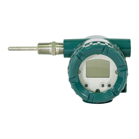
YOKOGAWA YTA710 User Manual
Temperature transmitter (brain protocol)
Hide thumbs
Also See for YTA710:
- User manual (133 pages) ,
- User manual (49 pages) ,
- User manual (85 pages)

Related Manuals for YOKOGAWA YTA710


Summary of Contents for YOKOGAWA YTA710
- Page 1 User’s Manual YTA710 Temperature Transmitter (BRAIN Protocol) IM 01C50T03-02EN IM 01C50T03-02EN 1st Edition...
-
Page 2: Table Of Contents
Checking for problems ..................4-1 History Functions ..................... 4-4 Self Check Function ..................4-7 List of Parameters ..................5-1 Parameter Copy ....................5-9 Revision Information 1st Edition: Mar. 2018 (KP) IM 01C50T03-02EN All Rights Reserved, Copyright © 2018, Yokogawa Electric Corporation... -
Page 3: Introduction
• All rights reserved. No part of this manual may be reproduced in any form without Yokogawa’s written permission. • Yokogawa makes no warranty of any kind with regard to this manual, including, but not limited to, implied warranty of merchantability and fitness for a particular purpose. -
Page 4: For Safe Use Of Product
- Failure or damage due to modification or (d) Modification repair by any party except Yokogawa or an • Yokogawa will not be liable for malfunctions or approved representative of Yokogawa. damage resulting from any modification made - Malfunction or damage from improper to this instrument by the customer. -
Page 5: Atex Documentation
<1. Introduction> ■ ATEX Documentation This procedure is only applicable to the countries in European Union. IM 01C50T03-02EN... -
Page 6: Connecting The Bt200
<2. Connecting the BT200> Connecting the BT200 Interconnection Between Communication Line YTA and BT200 Requirements [Protocol specification] Yokogawa original protocol IMPORTANT [Modulation] Burst modulation 0: 2400Hz • Analog output may change temporally in 1: Signal without carrier connecting with BRAIN terminal due to [Baud rate] 1200bps an initial current flowed to it. -
Page 7: Parameter Setting
<3. Parameter Setting> Parameter Setting IMPORTANT Do not turn off the power to the transmitter immediately after setup on the BT200. If the transmitter is turned off in less than 30 seconds after parameters have been set, the current parameter settings will not be stored in the transmitter. -
Page 8: Menu Tree Of Display
<3. Parameter Setting> Menu Tree of Display The following shows the menu structure of YTA710 parameters. HOME A:VARIABLE B:SET VAR CON. A10:PV B10:PV is A11:mA of RANGE B11:PV UNIT A12:% of RANGE B20:SV is A20:SV B21:SV UNIT A30:TV B30:TV is... -
Page 9: Parameter Description
<3. Parameter Setting> Parameter Description • Test Output (→3.2.8) This function can output any value as DC output. The following outlines the setting items for YTA Use it for loop check. An output of any value BRAIN protocol. Before starting operations, review between 3.6 mA and 21.6 mA can be set. -
Page 10: Checking Sensor Connection
<3. Parameter Setting> 3.2.1 Checking Sensor Connection Confirm that the wires are connected correctly as shown below according to the sensor type to be used. Group A is thermocouple or DC voltage, and Group B is resistance temperature detector or resistance. 1-input model 2-input model Thermocouple and DC voltage (TC &... -
Page 11: Sensor Settings
<3. Parameter Setting> 3.2.2 Sensor settings Setting value Type Group Remarks Ni120 STI INC Resistance When changing sensor type, it is necessary to temperature change the parameters related to each sensor. detector Figure 3.1 shows both the wire connection to Cu10 SAMA Resistance RC21-4... -
Page 12: Process Variable Mapping
<3. Parameter Setting> 3.2.3 Process variable mapping 1-input 2-input Input Description Remarks model model The YTA temperature transmitter can handle four Average Mean value Same as process variables: primary variable (PV), secondary of Sensor1 above variable (SV), tertiary variable (TV), and quaternary and Sensor2 Sensor Sensor... -
Page 13: Unit
<3. Parameter Setting> 3.2.4 Unit 3.2.5 Range Setting A unit of the terminal block temperature can be The range setting refers to assigning an output set for process variables PV to QV, Sensor1, and range of 4 to 20 mA to an area (LRV to URV) within Sensor2 (the 2-input model only). -
Page 14: Damping Time Constant
<3. Parameter Setting> (1) Setting LRV and URV (2) Setting the calculation output lower limit and calculation output upper limit There are two ways to set the LRV and URV: by entering LRV and URV numeric values directly, and Set the calculation output lower limit and by providing real input. -
Page 15: Device Information (Tag Number, And Memory Writing)
<3. Parameter Setting> (1) Setting the damping time constant 3.2.7 Device information (tag number, and memory writing) The temperature transmitter calculates 63% of the input range to be output after the time period set by Parameter Format Remarks the damping time constant has elapsed. C01:TAG NO. -
Page 16: Burnout Function
3-10 <3. Parameter Setting> 3.2.9 Burnout Function IMPORTANT (1) Setting the output state at sensor burnout • The Test Output by the forced output function If a sensor mapped to the PV value is broken or if is automatically canceled 10 minutes (it is it has become disconnected from the terminal, you changeable by F30:RELEASE TIME setting) can set the output state. -
Page 17: Integral Indicator Display Mode
3-11 <3. Parameter Setting> 3.2.10 Integral Indicator Display Mode (2) Selecting the decimal-point position You can specify the position of the decimal point If the temperature transmitter has an integral (the number of digits displayed after the decimal indicator, you can set the display items and the point) for each display channel. -
Page 18: Write Protect
3-12 <3. Parameter Setting> The display order is switched in the following order 3.2.11 Write Protect for each display cycle. This function disables parameter writing, and Process variable protects the data set in the temperature transmitter. 2400 ms (Can be set by "J50: DISP CYCLE"... - Page 19 3-13 <3. Parameter Setting> (1) Checking the status This set password is only displayed on the confirmation screen immediately after it is set. You can check the current write protection state After that, the eight blank characters are always using the following two methods. However, you can displayed during normal parameter reading.
-
Page 20: Input Adjustment
If you forget your password, you can temporarily Upper trim cancel the write protection function using the “Joker” password. For the “Joker” password, Lower trim Lower trim contact Yokogawa sales office. Input Input Image of 1-point adjustment Image of 2-point adjustment F0312.ai Figure 3.4... - Page 21 3-15 <3. Parameter Setting> [Adjustment method] a. Power supply and output wiring Output signals Set the sensors before input adjustment. (→ 3.2.2 Reference input Load resistance Sensor Setup) generator (250 Ω) Use the following parameters for adjustment purposes. Sensor1 Sensor2 Voltmeter Usage parameter...
-
Page 22: Output Adjustment
3-16 <3. Parameter Setting> 3.2.13 Output Adjustment (1) Setting the sensor backup function (1) Set the “sensor type” and “number of wire The Output Adjustment function adjusts analog connections” of Sensor1 and Sensor2. If output values. When a precision ammeter (for Sensor1 and Sensor2 must measure the same calibration) is connected, when the 0% and 100% target (both should measure the temperature or... -
Page 23: Sensor Matching Function
C=Sensor-specific constant (0 if t>0°C) the sensor, and other measures). (2) Execute the parameter of the Sensor Backup These two equations are equivalent. Model YTA710 return instruction. can cope with either case (α, δ and β, or A, B and C) as above mentioned. -
Page 24: Cjc Function Selection
3-18 <3. Parameter Setting> IMPORTANT IMPORTANT • This function is only effective when the sensor When entering R , α, δ, β, A, B, C in the YTA, the type is set to “Sensor Matching”. following restrictions apply. • Enter the appropriate R value corresponding to •... - Page 25 3-19 <3. Parameter Setting> NOTE If you have selected the internal CJC, the settings in Steps (2) and (3) are not required. (2) Unit setting of cold junction compensation temperature Set the unit of cold junction compensation temperature using the following parameters. Setting Parameter Remarks...
-
Page 26: Self-Diagnostics
<4. Self-Diagnostics> Self-Diagnostics The temperature transmitter continually monitors its own performance during normal operation. If an error occurs, it displays and records the error in the logging parameters and the output vale that is off the scale, and with the integral indicator, an alarm number corresponding to the error is displayed, etc. - Page 27 <4. Self-Diagnostics> Table 4.1 Alarm List Indicator BRAIN configuration Output operation Cause Action display tool display upon error AL.00 CPU Failure The main CPU has failed. Data output and Device Replacement communication do not occur if the transmitter has failed. AL.01 Snsr NV Failure CRC mismatching of the...
- Page 28 <4. Self-Diagnostics> Indicator BRAIN configuration Output operation Cause Action display tool display upon error AL.23 Backup S1 Fail Sensor1 has failed during Output the backup side Check the soundness of sensor backup, and the Sensor2 data. If the backup side Sensor1.
-
Page 29: History Functions
If both Sensor1 and Sensor2 have failed, a Sensor Burnout is output History Functions NOTE The YTA710 temperature transmitter has the following history functions. While the Sensor Backup function is active, if both AL.23 Backup S1 Fail and AL.24 Backup S2 Fail (1) Alarm history occur, sensor burnout will occur. - Page 30 <4. Self-Diagnostics> (5) Log data NOTE The log data of LOG1 to LOG5 consists of the alarm data and the time information at this time. Also, the buffers are synchronized when the When the following parameters are read, the temperature transmitter is turned on. log data is displayed.
- Page 31 <4. Self-Diagnostics> (2) History of maximum and minimum (3) Operating time measurement values The operating time of the transmitter after factory The maximum and minimum measurement values shipment is shown. It can be checked using the of Sensor1, Sensor2 (for the 2-input model only), following parameters.
-
Page 32: Self Check Function
<4. Self-Diagnostics> Self Check Function (5) “RTD” or “ohm” short-circuit (for 3-wire/4- wire type only) The YTA has the following self-check functions. This function detects a short-circuit of the sensor during “RTD” or “ohm” measurement. If the sensor (1) Hardware failure resistance drops below the threshold (L11: S1 RC1 This function detects a failure of CPU, AD converter, to L14: S1 RC4, L17: S2RC4, L16: S2RC4), a... - Page 33 <4. Self-Diagnostics> (7) Sensor drift (for 2-input model only) (8) Temperature cycle diagnostics When the difference between Sensor1 and Sensor2 This function displays the number of temperature temperatures exceeds the threshold, a Sensor Drift fluctuations that may cause the sensor to fail. This alarm is output.
- Page 34 <4. Self-Diagnostics> (9) Sensor diagnostic information Information obtained by the sensor diagnostics is displayed in the parameters below. You can take advantage of the preventive maintenance of sensors by obtaining this information periodically. Table 4.3 Sensor1 diagnostics information Sensor type Parameter 3-wire 4-wire...
-
Page 35: List Of Parameters
Table 5.1 List of Parameters RW: Display/setting R: Display only Upload/ Name Description Remarks Default download parameter MODEL Model YTA710 Tag number Sixteen alphanumeric Specify during characters ordering. SELF CHECK Self-diagnosis GOOD, ERROR ― VARIABLE Process variable (Primary variable) Value specified in B10, ―... - Page 36 <5. List of Parameters> Upload/ Name Description Remarks Default download parameter SENSOR1 Sensor1 dumping RW 0 to 100 sec 2 sec DAMP S1 R0 Setting of sensor matching RW The unit is ohms. 100.00 ohms reference resistance S1 A IEC Primary coefficient setting of RW The unit is fixed to E-3.
- Page 37 <5. List of Parameters> Upload/ Name Description Remarks Default download parameter AO DAMP PT Threshold of current output RW 0 to 99% dumping calculation BURN OUT Sensor burnout RW LOW HIGH HIGH USER BURN OUT User output mA value for sensor RW 3.6 to 21.6 mA 21.6 mA ...
- Page 38 <5. List of Parameters> Upload/ Name Description Remarks Default download parameter TERM LSL Lower limit temperature of terminal -200.0 degC sensor measuring range TERM USL Upper limit temperature of terminal +850.0 degC sensor measuring range TERM MIN Terminal sensor minimum span 10.0 degC SELF CHECK Self-diagnosis...
- Page 39 <5. List of Parameters> Upload/ Name Description Remarks Default download parameter NRML MIN Setting of operation output lower RW 3.60 to 4.00 mA 3.68 mA limit NRML MAX Setting of operation output upper RW 20.00 to 21.60 mA 20.8 mA ...
- Page 40 <5. List of Parameters> Upload/ Name Description Remarks Default download parameter S1 CORR Mask setting for S1 Corrosion RW NO MASK MASK MASK alarm MASK S2 CORR Mask setting for S2 Corrosion RW NO MASK MASK MASK alarm MASK S1 SGER Mask setting for S1 Signal Error RW NO MASK NO MASK...
- Page 41 <5. List of Parameters> Upload/ Name Description Remarks Default download parameter S1 RC1 Sensor1 diagnostic resistance (Resistance between pin #1 and sensor) S1 RC2 Sensor1 diagnostic resistance (Resistance between pin #2 and sensor) S1 RC3 Sensor1 diagnostic resistance (Resistance between pin #3 and sensor) S1 RC4 Sensor1 diagnostic resistance...
- Page 42 0d00:00 time SELF CHECK Self-diagnosis Same as A60 ― DEVICE INFO Device information MS CODE1 MS code 1 Sixteen alphanumeric YTA710 characters MS CODE2 MS code 2 Sixteen alphanumeric Sixteen blank characters characters MS CODE3 MS code 3 Sixteen alphanumeric...
-
Page 43: Parameter Copy
Only displayed when the additional specification code/ Using the upload and download functions, the CM1 is specified. user can copy the YTA710 setting data to another YTA710 temperature transmitter. IMPORTANT Use the procedure below to copy the data. (1) Upload... -
Page 44: Revision Information
Revision Information Title : YTA710 Temperature Transmitter Functions (BRAIN Protocol) Manual No. : IM 01C50T03-02EN Edition Date Page Revised Item Mar. 2018 — New Publication IM 01C50T03-02EN...
Need help?
Do you have a question about the YTA710 and is the answer not in the manual?
Questions and answers