YOKOGAWA YTA Series User Manual
Temperature transmitters
Hide thumbs
Also See for YTA Series:
- User manual (133 pages) ,
- User manual (61 pages) ,
- User manual (44 pages)

Related Manuals for YOKOGAWA YTA Series


Summary of Contents for YOKOGAWA YTA Series
- Page 1 User's Manual YTA Series Temperature Transmitters (Hardware) [Style: S2] IM 01C50B01-01E IM 01C50B01-01E 8th Edition Y okogawa Electric Corporation...
-
Page 3: Table Of Contents
Cable and Terminal Connections ............5-2 5.4.1 Input Terminal Connections ............5-2 5.4.2 Output Terminal Connection ............5-3 Wiring Cautions ................... 5-4 Grounding .................... 5-5 FD No. IM 01C50B01-01E IM 01C50B01-01E 8th Edition: May 2002(YK) All Rights Reserved, Copyright © 1998, Yokogawa Electric Corporation... - Page 4 CONTENTS MAINTENANCE ..................... 6-1 General ....................6-1 Calibration ................... 6-1 6.2.1 Selection of Equipment for Calibration ........6-1 6.2.2 Calibration Procedure ..............6-1 Disassembly and Assembly ..............6-2 6.3.1 Replacement of Built-in Indicator ..........6-3 6.3.2 Replacement of CPU Assembly ........... 6-3 Troubleshooting ...................
-
Page 5: Preface
Notes on Safety and Modifications maintenance descriptions. When these procedures • Before handling the YTA, it is absolutely imperative are needed, please contact nearest YOKOGAWA that users of this equipment read and observe the office. safety instructions mentioned in each section of the •... -
Page 6: Warranty
1. PREFACE Symbols used in this Instruction Manual Warranty The YTA temperature transmitter and this manual use • The warranty period of the instrument is written on the following safety related symbols and signals. the estimate sheet that is included with your pur- chase. -
Page 7: Notes On Handling
2. NOTES ON HANDLING NOTES ON HANDLING 2.2 Transport The YTA temperature transmitter is fully factory- tested upon shipment. When the YTA is delivered, To prevent damage while in transit, leave the transmit- check the appearance for damage, and also check that ter in the original shipping container until it reaches the transmitter mounting parts shown in Figure 2.1 are the installation site. -
Page 8: Use Of A Transceiver
2. NOTES ON HANDLING (3) Impact and Vibration 4. Turn the power of the insulation resistance meter It is recommended that the instrument be installed in a ON and measure the insulation resistance. The location that is subject to a minimum amount of impact duration of the applied voltage must be the period and vibration. -
Page 9: Withstand Voltage Test Procedure
2. NOTES ON HANDLING 2.6.2 Withstand voltage test procedure 2.7 Installation of Explosion Protected Type Transmitters Testing between the output terminal and the input terminal In this section, further requirements and differences 1. Lay transition wiring between the + terminal, the – and for explosionproof type instrument are described. - Page 10 • The instrument modification or parts replacement by • When installed in Division 2, “FACTORY other than authorized representative of Yokogawa SEALED, CONDUIT SEAL NOT REQUIRED”. Electric Corporation is prohibited and will void Note 3. Operation Canadian Standards Intrinsically safe and •...
-
Page 11: Cenelec Atex (Kema) Certification
Note 4. Maintenance and Repair safe type • The instrument modification or parts replacement by Note 1. Model YTA110/KU2, YTA310/KU2 and other than authorized representative of Yokogawa YTA320/KU2 temperature transmitters for Electric Corporation is prohibited and will void potentially explosive atmospheres: KEMA Intrinsically safe Certification. - Page 12 • The instrument modification or parts replacement by event of rare incidents, ignition source due to impact other than authorized representative of Yokogawa and friction sparks are excluded. Electric Corporation is prohibited and will void KEMA Flameproof Certification.
- Page 13 2. NOTES ON HANDLING (5) Maintenance and Repair Note 4. Maintenance and Repair • The instrument modification or parts replacement by other than authorized representative of Yokogawa WARNING Electric Corporation is prohibited and will void The instrument modification or parts replacement Type of Protection “n”...
-
Page 14: Cenelec (Kema) Certification
(Refer to the installation diagram) • The instrument modification or parts replacement by Note 4. Maintenance and Repair other than authorized representative of Yokogawa • The instrument modification or parts replacement by Electric Corporation is prohibited and will void other than authorized representative of Yokogawa KEMA Flameproof Certification. -
Page 15: Fm Certification
Voc , Isc, Ca and La are parameters of the safety • The instrument modification or parts replacement by barrier. other than authorized representative of Yokogawa Note 3. Installation Electric Corporation is prohibited and will void • The safety barrier must be FM approved. - Page 16 Class II and III environments. – Note 4. Maintenance and Repair • The instrument modification or parts replacement by Intrinsically Safe Sensor other than authorized representative of Yokogawa or Simple Temperature Electric Corporation is prohibited and will void Apparatus Safety Barrier...
-
Page 17: Jis Certification
REQUIRED”. INSTALL IN ACCOR- the confirmation. DANCE WITH THE INSTRUCTION Note that the rated current of the YTA series in MANUAL IM 1C50B1. terms of explosion protection is 4 to 20 mA; keep the input current of the YTA series within •... -
Page 18: Emc Conformity Standards
YOKOGAWA recommends customer to apply the Metal Conduit Wiring or to use the twisted pair Shield Cable for signal wiring to conform the requirement of EMC Regulation, when customer installs the YTA Series Transmitters to the plant. IM 01C50B01-01E 2-12... -
Page 19: Part Names And Functions
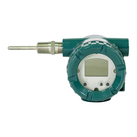
3. PART NAMES AND FUNCTIONS PART NAMES AND FUNCTIONS 3.1 Part Names Burn out output direction setting pin upon hardware failure Name plate Stud bolt CPU assembly Terminal cover LCD assembly (with indicator) Grounding Amp. cover terminal Tag plate Grounding terminal Lock screw Wiring connector... -
Page 20: Setting The Hardware Error Burnout Change-Over Switch
3. PART NAMES AND FUNCTIONS (1)Output bar chart display 3.2 Setting the Hardware Error The output value is displayed in a bar chart. Resolution Burnout Change-over Switch of the bar chart is to the extent of 32 divisions (each increment is about 3.125%). If the output exceeds 0% The temperature transmitter is equipped with a hard- or 100%, is lit. - Page 21 3. PART NAMES AND FUNCTIONS (6)Unit display Upon shipment from the factory, the indicator is set as The unit specified as the unit of process in the process follows. variable display column in Item (5) is lit. The output Table 3.2 Setting of Indicator upon Shipment from the display is fixed to mA or %.
-
Page 22: Installation
4. INSTALLATION INSTALLATION Horizontal Pipe Mounting IMPORTANT • When performing on-site pipe fitting work that involves welding, use care to prevent outflow of the welding current into the transmitter. • Do not use the transmitter as a foothold for installation. U-bolt nut •... -
Page 23: Wiring
Figure 5.3. For details of communication requirements, refer to the additional reference materials, IM 01C50T03-01E “YTA Series BRAIN Communication”, and IM 01C50T01-01E “YTA Series HART Communication”. IM 01C50B01-01E... -
Page 24: Cable Selection
5. WIRING 5.3 Cable Selection CAUTION 5.3.1 Input signal Cable Selection When wiring, pay attention not to damage the A dedicated cable is used for connection between the cable and cores. All the cores of the cable must temperature sensor and the temperature transmitter. have the sufficient insulation around them. -
Page 25: Output Terminal Connection
5. WIRING 5.4.2 Output Terminal Connection Sensor1(YTA110, YTA310) (1) Connection of output signal/power supply cable (–) Connect the output signal cable (shared with the power supply cable) to the – terminal and the + Thermocouple and RTD and resistance terminal. For details, refer to Figure 5.2, “Loop DC voltage (2-wire) construction”. -
Page 26: Wiring Cautions
Tighten the union cover approximately one turn • Use only flameproof packing adapters approved by after the point where you can no longer shift the Yokogawa. cable up and down by hand. Take great care in • Apply a nonhardening sealant to the terminal box this step, since proper tightening is very important. -
Page 27: Grounding
5. WIRING 5.6 Grounding Flameproof metal conduit wiring • A seal fitting must be installed near the terminal Grounding should satisfy JIS Class D requirements box connection port for a sealed construction. (with ground resistance of 100 or less). Grounding •... -
Page 28: Maintenance
6. MAINTENANCE MAINTENANCE 6.1 General Table 6.1 Calibration Equipment List Name Recommended Remark Each component of this instrument is configured in Power supply SDBT, SDBS 4 to 20mA DC units to make maintenance easier. type distributor (Output voltage: 26.5 1.5V, drop by This chapter contains disassembly and assembly internal 250 procedures associated with calibration, adjustment and... -
Page 29: Disassembly And Assembly
6. MAINTENANCE Table 6.2 Tools for Disassembly and Assembly 3. For thermocouple input Since this instrument is equipped with a reference Tool name Quantity Remark junction compensating function, use a reference Phillips screwdriver junction compensating function in universal Standard screwdriver Hexagonal wrench calibrator in order to compensate for this function Crescent wrench... -
Page 30: Replacement Of Built-In Indicator
6. MAINTENANCE 6.3.1 Replacement of Built-in Indicator 6.3.2 Replacement of CPU Assembly Removal of built-in indicator Removal of CPU assembly 1. Remove the cover. 1. Remove the cover. 2. Loosen two mounting screws while using your hand 2. Use a Phillips screwdriver to loosen the two screws. to support the built-in indicator. -
Page 31: Troubleshooting
6. MAINTENANCE 6.4 Troubleshooting 6.4.2 Example of Troubleshooting Flow When the measured value is found abnormal, follow The following phenomena indicate that this the troubleshooting flowchart below. If the complex instrument may be out of operation. nature of the trouble means that the cause cannot be [Example] identified using the following flowchart, refer the •... - Page 32 6. MAINTENANCE Table 6.3 Problems, Causes and Countermeasures Related Parameter Observed Problems Possible Cause Countermeasure (BRAIN protocol) (HART protocol) Output fluctuates Span is too narrow. Check the range, and change the F10:LRV PV LRV (4) greatly. settings to make the span larger. F20:URV PV URV (5) Input adjustment by user was...
-
Page 33: Integral Indicator And Error Display
6. MAINTENANCE 6.5 Integral Indicator and Error Display For temperature transmitters equipped with an integral indicator, errors in the temperature sensor or the transmitter cause an integral indicator to call up the applicable error code. Table 6.4 lists the error codes and the associated corrective actions. -
Page 34: Standard Specifications
7. STANDARD SPECIFICATIONS STANDARD SPECIFICATIONS 7.1 Standard Specifications Communication line conditions( ): Power supply voltage; 16.4 to 42 VDC For the specifications of Fieldbus communication type Load resistance; 250 to 600 (including cable marked with ( ), refer to IM 01C50T02-01E. resistance) For relation between power supply voltage and Input signal:... - Page 35 7. STANDARD SPECIFICATIONS Ambient humidity: 5 to 100%RH at 40°C (104°F) Effect of supply voltage fluctuation: ±0.005%/V Insulation: Input/output insulated at 500 V AC Mounting: Mounted on 2B pipes and wall Waterproofing: JIS0920, water-resistant type (equivalent of NEMA TYPE4X) Electrical connection: Refer to “Model and Specification Codes”.
- Page 36 7. STANDARD SPECIFICATIONS Table 7.1 Input Type, Measurement Range and Accuracy Accuracy Measurement Range Minimum Span Reference Sensor Type Input range A/D Accuracy (Recommended) Standard Accuracy 100 to 212 to 100 to 1820 212 to 3308 300 to 572 to 400 to 1820 752 to 3308 0.75...
- Page 37 7. STANDARD SPECIFICATIONS Table 7.2 YTA110 Effect of Ambient Temperature Sensor Type Temperature Coefficient Thermocouples E, J, K, N, T, L, U 0.08 C + 0.02% of abs.reading Thermocouples R, S, W3, W5 0.25 C + 0.02% of abs.reading 100 C Reading <...
-
Page 38: Model And Suffix Codes
7. STANDARD SPECIFICATIONS Factory setting ( ) Tag No. Left blank if not specified in order Input sensor type “Pt100, 3-wire” if not specified in order Lower bound of calibration range “0” if not specified in order Upper bound of calibration range “100”... - Page 39 *1 : Applicable for Electrical Connection Code 2 and 4. *2 : Applicable for Electrical Connection Code 2. *3 : If cable wiring is to be used to a JIS flameproof type transmitter, do not fail to add the YOKOGAWA-assured flameproof packing adapter.
-
Page 40: Dimensions
7. STANDARD SPECIFICATIONS Descriptions Code Item CSA Intrinsically safe, non-incendive and Explosionproof approval combination* [Intrinsically safe/non-incendive approval] Intrinsically safe for Class I, Division 1, Groups A, B, C and D; Class II, Division 1, Groups E, F and G; Class III, Division 1: Non-incendive for Class I, Division 2, Groups A, B, C and D;... -
Page 41: Installation And Operating Precautions For Jis Flameproof Equipment
INSTALLATION AND OPERATING PRECAUTIONS FOR JIS FLAMEPROOF EQUIPMENT INSTALLATION AND OPERATING PRECAUTIONS FOR JIS FLAMEPROOF EQUIPMENT Apparatus Certified Under Technical Criteria (IEC-compatible Standards) 1. General construction is of completely enclosed type and its enclosure shall endure explosive pressures in cases where explosive The following describes precautions on electrical apparatus gases or vapours entering the enclosure cause explosion. - Page 42 INSTALLATION AND OPERATING PRECAUTIONS FOR JIS FLAMEPROOF EQUIPMENT 4. Installation of Flameproof • Specific cables shall be used as recommended by the “USER’S GUIDELINES for Electrical Installations for Apparatus Explosive Gas Atmospheres in General Industry,” published in 1994. (1) Installation Area •...
- Page 43 So, (2) Repair Yokogawa-specified cable entry devices for flameproof type shall be used to meet this demand. If the flameproof apparatus requires repair, turn off the power and transport it to a safety (non-hazardous) location.
-
Page 45: Customer Maintenance Parts List
Customer YTA Series Maintenance Temperature Transmitter Parts List [ Style : S2 ] For F Fieldbus Type OUNDATION YTA_CMPL.EPS All Rights Reserved, Copyright © 1998, Yokogawa Electric Corporation. CMPL 01C50B01-02E 8th Edition: Oct. 2001 (YK) Yokogawa Electric Corporation... - Page 46 Item Part No. Description F9165EA Cover B1000ER O-Ring Y9406JB Screw Machine See Table 1 CPU Assembly for BRAIN or HART Communication type B1002BT Stud Bolt F9342MW Connector Assembly F9165DH Name Plate F9300AG Screw F9165DF Tag Plate F9300AG Screw F9165FA Cover Assembly F9167DA LCD Assembly B1001BT...
-
Page 47: Revision Record
REVISION RECORD Title: Model YTA series Temperature Transmitter (Hardware) [Style: S2] Manual No.: IM 01C50B01-01E Edition Date Page Revised item Sep. 1998 — New Publication Nov. 1998 2.7.1 Add subsection 2.7.1 CSA certification. 2.7.2 Add subsection 2.7.2 CENELEC(KEMA) certificated. Add subsection 2.8 EMC Conformity Standards.
Need help?
Do you have a question about the YTA Series and is the answer not in the manual?
Questions and answers