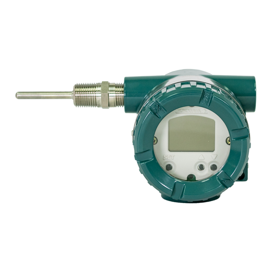
YOKOGAWA YTA610 User Manual
Temperature transmitters
Hide thumbs
Also See for YTA610:
- User manual (85 pages) ,
- User manual (6 pages) ,
- User manual (133 pages)
Advertisement
User's
Manual
Please use this manual change with the user's manuals listed below.
1. Applicable User's Manual and Page
IM No. (Edition)
IM 01C50T03-02EN(1)
YTA610 and YTA710
Temperature Transmitters
(BRAIN Protocol)
Applicable part
Page
3-10
3.2.9 Burnout Function
3-16
3.2.14 Sensor Backup(for the 2-input model only)
4-2
Table 4.1 List of Alarms
Table 4.1 List of Alarms
4-3
Table 4.2 Output Operation
4-4
4-7
4.3 Self Check Function
Manual Change No. 18-0027-E
Revised contents
Change CAUTION.
Add NOTE.
Change CAUTION.
Add *1 and *2.
Add *1 and *2.
Add *2.
Add NOTE.
Oct. 19, 2018
Advertisement
Table of Contents

Subscribe to Our Youtube Channel
Summary of Contents for YOKOGAWA YTA610
- Page 1 YTA610 and YTA710 User’s Temperature Transmitters Manual (BRAIN Protocol) Manual Change No. 18-0027-E Please use this manual change with the user’s manuals listed below. 1. Applicable User’s Manual and Page IM No. (Edition) Applicable part Revised contents Page 3-10 3.2.9 Burnout Function Change CAUTION.
-
Page 2: Burnout Function
3-10 <3. Parameter Setting> IMPORTANT CAUTION • The Test Output by the forced output function There is a time lag between sensor failure and is automatically canceled 10 minutes (it is sensor abnormality detection. changeable by F30:RELEASE TIME setting) Since the failed measurement value is output, the after changing to MANUAL MODE. - Page 3 3-16 <3. Parameter Setting> 3.2.13 Output Adjustment (1) Setting the sensor backup function (1) Set the “sensor type” and “number of wire The Output Adjustment function adjusts analog connections” of Sensor1 and Sensor2. If output values. When a precision ammeter (for Sensor1 and Sensor2 must measure the same calibration) is connected, when the 0% and 100% target (both should measure the temperature or...
- Page 4 <4. Self-Diagnostics> Table 4.1 Alarm List Indicator BRAIN configuration Output operation Cause Action display tool display upon error AL.00 CPU Failure The main CPU has failed. Data output and Device Replacement communication do not occur if the transmitter has failed. AL.01 Snsr NV Failure CRC mismatching of the...
- Page 5 <4. Self-Diagnostics> Indicator BRAIN configuration Output operation Cause Action display tool display upon error AL.23 Backup S1 Fail Sensor1 has failed during Output the backup side Check the soundness of sensor backup, and the Sensor2 data. If the backup side Sensor1.
-
Page 6: History Functions
<4. Self-Diagnostics> The sensor burnout conditions depend on the setting of current output mapping, and the alarm occurred. These conditions are as follows. Table 4.2 Output Operations Current output S1 Failure S2 Failure S1 Short S2 Short Term Sensor Fail mapping SENS.1 Sensor burnout... -
Page 7: Self Check Function
<4. Self-Diagnostics> Self Check Function NOTE The YTA has the following self-check functions. In order to output the S1 (or S2) Short alarm, (1) Hardware failure "K12:S1 SHRT MASK" and "K13:S2 SHRT MASK" must be set to "NO MASK". (The alarm is This function detects a failure of CPU, AD converter, masked by default.) memory and others.


Need help?
Do you have a question about the YTA610 and is the answer not in the manual?
Questions and answers