Sign In
Upload
Manuals
Brands
YOKOGAWA Manuals
Transmitter
YTA710
YOKOGAWA YTA710 Manuals
Manuals and User Guides for YOKOGAWA YTA710. We have
7
YOKOGAWA YTA710 manuals available for free PDF download: User Manual
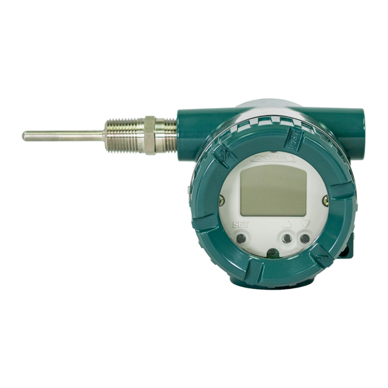
YOKOGAWA YTA710 User Manual (133 pages)
Temperature Transmitters Fieldbus Communication
Brand:
YOKOGAWA
| Category:
Transmitter
| Size: 2 MB
Table of Contents
Table of Contents
2
Introduction
7
Regarding this Manual
7
For Safe Use of Product
8
Warranty
8
Part Names
9
About Fieldbus
10
Outline
10
Internal Structure of YTA
10
System/Network Management VFD
10
Function Block VFD
10
Logical Structure of each Block
10
Wiring System Configuration
11
Getting Started
12
Connection of Devices
12
Host Setting
13
Bus Power on
13
Integral Indicator Display When Powering on
13
Confirming that Transmitter Is Operating Properly
14
Integration of DD
14
Set the Parameters Using DTM
14
Reading the Parameters
14
Continuous Record of Values
15
Generation of Alarm
15
Configuration
16
Network Design
16
Network Definition
17
Definition of Combining Function Blocks
18
Setting of Tags and Addresses
19
Communication Setting
19
VCR Setting
19
Function Block Execution Control
20
Block Setting
21
Link Object
21
Trend Object
21
View Object
21
Explanation of Basic Items
28
Outline
28
Setting and Changing Parameters for the Whole Process
28
SENSOR Transducer Block (STB)
28
Functional Block
28
Block Mode
28
Parameters of SENSOR Transducer Block
29
Sensor Trim
33
Sensor Failure
37
LCD Transducer Block (LTB)
41
Outline of the Functions
41
Block Mode
41
Display Contents of the Integral Indicator
41
Procedure to Set the Built-In Display
42
Maintenance Transducer Block (MTB)
43
Logging Functions
43
Alarm Log
43
Operation Time
43
AI Function Block
44
Function Blocks
44
Block Mode
44
Io_Opts
44
Status_Opt
44
Basic Parameters of the AI Block
45
DI Function Block
46
In-Process Operation
47
Mode Transition
47
Generation of Alarm
47
Indication of Alarm
47
Alarms and Events
47
Alarm Handling
48
Field Diagnostics
51
Simulation Function
58
Simulate Enable
58
Write Lock (Write-Protect) Function
59
Appendix 1. List of Parameters for each Block of the YTA
60
A1.1 Resource Block
60
A1.2 SENSOR Transducer Block (STB)
64
A1.3 LCD Transducer Block (LTB)
70
A1.4 Maintenance Transducer Block (MTB)
71
A1.5 AI Function Block
73
A1.6 DI Function Block
75
A1.7 Unit and Code
76
Appendix 2. Signal Characterizer (SC) Block
77
Input/Output Parameters
77
A2.1 Schematic Diagram of Signal Characterizer Block
77
A2.2 Input Section
78
A2.2.1 Determining the Mode
78
A2.3 Line-Segment Factor Determination Section
79
A2.3.1 Conditions for Configuring Valid Coefficients (CURVE_X, CURVE_Y)
79
A2.4 List of Signal Characterizer Block Parameters
81
A2.5 Application Example
82
A2.5.1 Input Compensation
82
A2.5.2 Calorie Flow Compensation
82
A2.5.3 Backward Control
83
Appendix 3. Input Selector (IS) Block
84
A3.1 Input Selector Function Block Schematic
84
Other Parameters
85
A3.2 Input Section
86
A3.2.1 Mode Handling
86
A3.2.2 MIN_GOOD Handling
87
A3.3 Selection
88
A3.3.1 OP_SELECT Handling
88
A3.3.2 SELECTION Handling
89
A3.4 Output Processing
95
A3.4.1 Handling of SELECTED
95
A3.4.2 out Processing
96
A3.4.3 Status_Opts
97
A3.5 List of Input Selector Block Parameters
97
A3.6 Application Example
99
Appendix 4. Arithmetic (AR) Block
100
A4.1 Arithmetic Function Block Schematic
100
A4.2 Input Section
101
A4.2.1 Main Inputs
101
A4.2.2 Auxiliary Inputs
101
A4.2.3 Input_Opts
102
A4.2.4 Relationship between the Main Inputs and PV
102
A4.3 Computation Section
103
A4.3.1 Computing Equations
103
A4.3.2 Compensated Values
103
A4.3.3 Average Calculation
103
A4.4 Output Section
103
A4.4.1 Mode Handling
104
A4.4.2 Status Handling
104
A4.5 List of the Arithmetic Block Parameters
105
Appendix 5. PID Block
107
A5.1 Function Diagram
107
A5.2 Functions of PID Block
107
Control Output
107
A5.5 Control Output
110
A5.7 Control Action Bypass
111
A5.8 Feed-Forward
111
A5.9 Block Modes
111
A5.9.1 Mode Transitions
111
A5.10 Bumpless Transfer
112
A5.11 Setpoint Limiters
112
A5.11.1 When PID Block Is in Auto Mode
112
A5.11.2 When PID Block Is in cas or Rcas Mode
112
A5.12 External-Output Tracking
113
A5.13 Measured-Value Tracking
113
A5.14 Initialization and Manual Fallback (Iman)
113
A5.15 Manual Fallback
114
A5.16 Auto Fallback
114
A5.17 Mode Shedding Upon Computer Failure
114
A5.18.2 Process Alarms
115
A5.18
115
A5.19 Example of Block Connections
115
Appendix 6. Link Master Functions
117
A6.1 Link Active Scheduler
117
A6.2 Link Master
117
A6.3 Transfer of las
118
A6.4 LM Functions
119
A6.5 LM Parameters
120
A6.5.1 LM Parameter List
120
A6.5.2 Descriptions for LM Parameters
122
A6.6 Faqs
124
Appendix 7. Software Download
126
A7.1 Benefits of Software Download
126
A7.2 Specifications
126
A7.3 Preparations for Software Downloading
126
A7.4 Software Download Sequence
127
A7.5 Download Files
127
A7.6 Steps after Activating a Field Device
128
A7.7 Troubleshooting
128
A7.8 Maintenance Transducer Block's Parameters Relating to Software Download
129
A7.9 System/Network Management VFD Parameters Relating to Software Download
130
A7.10 Comments on System/Network Management VFD Parameters Relating to Software Download
131
Revision Information
133
Advertisement
Yokogawa YTA710 User Manual (85 pages)
YTA Series, Temperature Transmitters
Brand:
Yokogawa
| Category:
Transmitter
| Size: 4 MB
Table of Contents
Table of Contents
2
1 Preface
4
Notes on the User's Manual
4
Notes on Safety and Modifications
4
For Safe Use of Product
5
Warranty
6
Trademarks
6
ATEX Documentation
7
Control of Pollution Caused by the Product
8
2 Notes on Handling
9
Nameplate
9
Transport
9
Storage
9
Choosing the Installation Location
9
Use of a Transceiver
10
Insulation Resistance Test and Withstand Voltage Test
10
Insulation Resistance Test Procedure
10
Withstand Voltage Test Procedure
11
Installation of Explosion Protected Type Transmitters
12
ATEX Certification
12
Iecex Certification
16
FM Certification
18
CSA Certification
19
Control Drawing
22
EMC Conformity Standards
38
Safety Requirement Standards
38
3 Part Names and Functions
39
Part Names
39
Hardware Error Burnout and Hardware Write Protect Switch
39
Integral Indicator Display Function
40
Local Parameter Setting
41
Local Parameter Setting (LPS) Overview
41
Parameters Configuration
44
4 Installation
46
5 Wiring
47
Notes on Wiring
47
Loop Construction
47
Cable Selection
48
Input Signal Cable Selection
48
Output Signal Cable Selection
48
Cable and Terminal Connections
48
Input Terminal Connections
48
Output Terminal Connection
49
Wiring Cautions
50
Grounding
50
6 Maintenance
51
General
51
Calibration
51
Selection of Equipment for Calibration
51
Calibration Procedure
51
Disassembly and Assembly
52
Replacement of Integral Indicator
53
Troubleshooting
54
Basic Troubleshooting Flow
54
Example of Troubleshooting Flow
54
Integral Indicator and Error Display
56
7 General Specifications
60
Standard Specifications
60
Yta710
60
Yta610
66
Model and Suffix Codes
71
Optional Specifications (YTA610 and YTA710)
72
Dimensions (YTA610 and YTA710)
83
Revision Information
84
YOKOGAWA YTA710 User Manual (49 pages)
Temperature Transmitters (HART Protocol)
Brand:
YOKOGAWA
| Category:
Transmitter
| Size: 2 MB
Table of Contents
Table of Contents
2
1 Introduction
4
Regarding this Manual
4
For Safe Use of Product
5
Warranty
5
Matching of DD and Instruments
6
2 Connection
7
Integral Indicator Display When Powering on
7
Interconnection between YTA and HART Configuration Tool
7
Power Supply Voltage and Load Resistance
7
3 Parameter Setting
8
Menu Tree
8
Parameter Description
17
Review
18
Basic Setup
19
Sensor Configuration
19
Process Variable Mapping
19
Unit
20
PV Range
20
Damping Time Constant
20
Detailed Setup
21
Device Information
21
Test Output
21
Burnout Function
22
Integral Indicator Display Mode
22
Write Protect
23
Sensor Trim
24
Analog Output Trim
24
Sensor Backup (for Dual Input Type Only)
25
Burst Mode
25
Multidrop Mode
28
Sensor Matching Function
28
Cjc Selection
30
Tc User Table
30
Simulation
30
Squawk
31
Output Fluctuation Suppression
31
4 Diagnostics
33
Self-Diagnostics
33
Checking For Problems
33
Status Information
33
Logging Functions
36
Diagnostics Function
36
5 Parameters Lists
42
Appendix A. Safety Instrumented Systems Installation
45
Scope and Purpose
45
Hardware And Software Revision
45
Using the YTA for an SIS Application
45
Safety Accuracy
45
Diagnostic Response Time
45
Setup
45
Required Parameter Settings
45
Proof Testing
46
Repair And Replacement
47
Startup Time
47
Firmware Update
47
Reliability Data
47
Lifetime Limits
47
Environmental Limits
47
Application Limits
47
Terms and Definitions
47
Revision Information
49
Advertisement
YOKOGAWA YTA710 User Manual (44 pages)
Temperature Transmitter (BRAIN Protocol)
Brand:
YOKOGAWA
| Category:
Transmitter
| Size: 2 MB
Table of Contents
Table of Contents
2
1 Introduction
3
Regarding this Manual
3
For Safe Use of Product
4
Warranty
4
ATEX Documentation
5
2 Connecting the BT200
6
Interconnection between YTA and BT200
6
Communication Line Requirements
6
3 Parameter Setting
7
Menu Tree of Display
8
Parameter Description
9
Checking Sensor Connection
10
Sensor Settings
11
Process Variable Mapping
12
Unit
13
Range Setting
13
Damping Time Constant
14
Device Information (Tag Number, and Memory Writing)
15
Test Output
15
Burnout Function
16
Integral Indicator Display Mode
17
Write Protect
18
Input Adjustment
20
Output Adjustment
22
Sensor Backup (for the 2-Input Model Only)
22
Sensor Matching Function
23
CJC Function Selection
24
4 Self-Diagnostics
26
Checking for Problems
26
History Functions
29
Self Check Function
32
5 List of Parameters
35
Parameter Copy
43
Revision Information
44
Yokogawa YTA710 User Manual (6 pages)
Temperature Transmitters
Brand:
Yokogawa
| Category:
Transmitter
| Size: 2 MB
Table of Contents
Integral Indicator Display Mode
2
Burnout Function
2
3. Parameter Setting
2
Burst Mode
3
4. Diagnostics
4
Table 4.1 List of Alarms
4
Logging Functions
6
Diagnostics Function
6
Table 4.2 Output Operation
6
Yokogawa YTA710 User Manual (7 pages)
Temperature Transmitters
Brand:
Yokogawa
| Category:
Transmitter
| Size: 2 MB
Table of Contents
Burnout Function
2
History Functions
6
Alarm History
6
Self Check Function
7
YOKOGAWA YTA710 User Manual (2 pages)
Temperature Transmitters
Brand:
YOKOGAWA
| Category:
Transmitter
| Size: 2 MB
Table of Contents
Applicable User’s Manual and Page
1
Explanation of Basic Items
2
Parameters of SENSOR Transducer Block
2
Parameters Related to Limit Switches
2
Advertisement
Related Products
YOKOGAWA vigilantplant YTA70
YOKOGAWA YTA Series
YOKOGAWA YTA110
YOKOGAWA YTA310
YOKOGAWA YTA320
Yokogawa YTA610
yokogawa YTA510
YOKOGAWA YTA70P
YOKOGAWA YTMX580
YOKOGAWA Y/11GM
YOKOGAWA Categories
Measuring Instruments
Test Equipment
Transmitter
Controller
Media Converter
More YOKOGAWA Manuals
Login
Sign In
OR
Sign in with Facebook
Sign in with Google
Upload manual
Upload from disk
Upload from URL