
Subscribe to Our Youtube Channel
Related Manuals for YOKOGAWA YTA510


Summary of Contents for YOKOGAWA YTA510
- Page 1 User’s Manual YTA510 Temperature Transmitter IM 01C50E01-01EN IM 01C50E01-01EN 9th Edition Y okogawa Electric Corporation...
-
Page 2: Table Of Contents
Installation ....................4-1 Precautions ....................... 4-1 Mounting ......................4-1 Changing the Direction of Integral Indicator ..........4-2 Changing the Direction of the Antenna ............4-3 9th Edition: May 2017 (KP) IM 01C50E01-01EN All Rights Reserved, Copyright © 2010, Yokogawa Electric Corporation... - Page 3 Toc-2 Wiring ......................5-1 Notes on Wiring ....................5-1 Cable Selection ....................5-1 Cable and Terminal Connections ..............5-1 Wiring Cautions....................5-2 Mounting Antenna and Wiring ................. 5-2 5.5.1 Mounting the Antenna ................ 5-2 5.5.2 Mounting External Antenna and Wiring Antenna Extension Cable ... 5-3 5.5.2.1 Mounting of External Antenna ............
- Page 4 Toc-3 Self-Diagnostics ....................7-13 7.4.1 Identify Problems by Using the Communicator ....... 7-13 7.4.2 Alert Report ..................7-14 7.4.3 Checking with Integral Indicator ............7-15 Maintenance ....................8-1 General ....................... 8-1 Calibration Instruments Selection ..............8-1 Calibration Procedure ..................8-1 Disassembly and Assembly ................
-
Page 5: Introduction
This manual covers and describes for the • If the customer or any third party is harmed by detachable antenna type transmitters (Amplifier the use of this product, Yokogawa assumes housing code 8 or 9). no responsibility for any such harm owing to any defects in the product which were not predictable, or for any indirect damages. -
Page 6: Safe Use Of This Product
If these instructions are not heeded, the protection provided by this instrument may be (e) Modification impaired. In this case, Yokogawa cannot guarantee • Yokogawa will not be liable for malfunctions or that the instrument can be safely operated. Please damage resulting from any modification made pay special attention to the following points: to this instrument by the customer. -
Page 7: Radio Wave
Before using this instrument, ensure that - Failure or damage due to modification or neither a premises radio station nor specified repair by any party except Yokogawa or an low power radio station for mobile object approved representative of Yokogawa. identification systems is in use nearby. - Malfunction or damage from improper... -
Page 8: Atex Documentation
<1. Introduction> ATEX Documentation This is only applicable to the countries in European Union. IM 01C50E01-01EN... -
Page 9: Control Of Pollution Caused By The Product
○ 无线差压 / 压力 基板组件 × ○ ○ × ○ ○ 变送器 电源连接线 × ○ ○ ○ ○ ○ YTA510 天线组件 × ○ ○ ○ ○ ○ 无线温度变送器 电池组件 × ○ ○ ○ ○ ○ ○ : 表示该部件的所有均质材料中的有害物质的含量均在 GB/T26572 标准中所规定的限量以下。... -
Page 10: Notes On Handling
<2. Notes on Handling> Notes on Handling Check the Model Name and The YTA temperature transmitter is fully factory- tested upon shipment. When the YTA is delivered, configuration check the appearance for damage, and also check that the transmitter mounting parts shown The model name and configuration are indicated in Figure 2.1 are included with your shipment. -
Page 11: Choosing The Installation Location
<2. Notes on Handling> - Confirm that each field wireless equipment NOTE compliant with ISA100.11a can see the antenna of other devices which locate within When storing the instrument with a battery pack, its own communication range. In the star it is recommended to put the instrument in Deep topology network, the visibility to the antenna Sleep mode to conserve the batteries. -
Page 12: Insulation Resistance Test And Withstand Voltage Test
Please terminals while it is discharging. contact Yokogawa before making any repair or modification to an instrument. NOTE CAUTION When storing the instrument with a battery pack,... -
Page 13: Fm Approval
<2. Notes on Handling> Note 2. Output Parameters WARNING • Sensor Circuit ( 1 to 5 ) Maximum Output Voltage Voc: 6.6V Maximum Output Current Isc: 66mA The battery pack may be replaced in a Maximum Output Power Po: 109mW hazardous area. The battery pack has Maximum External Capacitance Ca: 22uF surface resistivity greater than 1G ohm and Maximum External Inductance La: 8.1mH must be properly installed in the enclosure... -
Page 14: Csa Certification
- the total Ci of the external circuit (excluding Approvals approval. the cable) is ≥ 1% of the Co value. • The reduced capacitance of the external Note 5. Battery Pack circuit (including cable) shall not be greater USE ONLY BATTERY PACK YOKOGAWA than 1μF for Group IIB and 600nF for Group F9915MA OR F9915NS. IIC. Note 6. Special Conditions for safe use Note 3. Installation POTENTIAL ELECTROSTATIC CHARGING • Installation should be in accordance with... -
Page 15: Atex Certification
<2. Notes on Handling> Note 4. Battery Pack Note 3. Installation Use only YOKOGAWA battery pack • Installation should be in accordance with F9915MA or F9915NS. local installation requirements. (Refer to the Control Drawing) Note 5. Special Conditions for safe use Potential electrostatic charging hazard- [Control Drawing] secure distance of 100mm from antenna. -
Page 16: Iecex Certification
Uo = 6.6V, Io = 66mA, Po = 109mW, Co = 22μF, Lo = 8.1mH POTENTIAL ELECTROSTATIC CHARGING HAZARD - SECURE DISTANCE WARNING OF 100MM FROM ANTENNA. parameters must be taken into account when USE ONLY BATTERY PACK YOKOGAWA F9915MA OR F9915NS. POTENTIAL ELECTROSTATIC CHARGING HAZARD - SEE USER'S MANUAL. installed. F0208.ai • The above parameters apply when one of MODEL: Specified model code. -
Page 17: Emc Conformity Standards
WARNING rubbed with cloth. The instrument modification or parts replacement by other than an authorized Representative of Low Voltage Directive Yokogawa Electric Corporation is prohibited and will void IECEx Intrinsically safe Certification. Applicable standard: EN61010-1, EN61010-2-030 Note 5. Battery Pack (1) Pollution Degree 2 • Use only YOKOGAWA battery pack... -
Page 18: Regulatory Compliance For Radio And Telecommunication
Terminal Equipment manual,may cause harmful interference to radio Directive (R&TTE) communications. Operation of this equipment in a residential area is likely to cause harmful We, Yokogawa Electric Corporation hereby declare interference in which case the user will be that this equipment,model YTA510 series is in required to correct the interference at his own compliance with the essential requirements and expense. -
Page 19: Rohs
2-10 <2. Notes on Handling> 2.14 RoHS has been approved by Industry Canada to operate with the antenna types listed below with the Applicable standard: EN50581 maximum permissible gain and required antenna (For the products delivered after July 1st, 2017) impedance for each antenna type indicated. Antenna types not included in this list, having a gain greater than the maximum gain indicated for that type, are strictly prohibited for use with this device. -
Page 20: Part Names And Functions
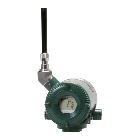
<3. Component Names> Part Names and Functions Antenna Terminal cover Grounding terminal CPU assembly Built-in indicator display RF assembly Write protection switch Slide Lock screw switch E WR Transmitter section H BO Amp. cover Burnout switch Hardware write protection switch (WR) Burnout switch (BO) Burnout Write Protection... -
Page 21: Installation
<4. Installation> Installation Precautions Mounting • Before installing the transmitter, read the • The mounting bracket shown in Figure 4.1 is cautionary notes in section 2.4, “Selecting the used for the transmitter and is installed on 50A Installation Location.” (2-inch) pipe. It can be installed either on a • For additional information on the ambient horizontal pipe and a vertical pipe or on a wall. conditions allowed at the installation location, •... -
Page 22: Changing The Direction Of Integral Indicator
<4. Installation> Horizontal Pipe Mounting (When using a vertical (When using a horizontal pipe mounting bracket) pipe mounting bracket) Bracket fastening bolt U-bolt nut Horizontal pipe mounting bracket Vertical pipe Spring washer mounting bracket Spring washer Transmitter fastening bolt Transmitter fastening bolt U-bolt nut Spring washer... -
Page 23: Changing The Direction Of The Antenna
<4. Installation> Changing the Direction of the Antenna Adjust the direction of the antenna to be in the upright position. The direction of antenna is like Figure 4.2 at the factory setting. When adjust the electrical connection vertically, change the direction of the antenna. To change the installation angle, follow the procedure below. -
Page 24: Wiring
The terminal of the dedicated cable is a 4 mm (B2) screw. (A2) Thermocouple and RTD and resistance DC voltage (3-wire) (A1) (B1) (–) (B2) (A2) Thermocouple + RTD and resistance RTD and resistance (2-wire) (3-wire) F0502.ai Figure 5.2 YTA510 Input Terminal Wire Connection Diagram IM 01C50E01-01EN... -
Page 25: Wiring Cautions
<5. Wiring> Wiring Cautions CAUTION Use metal conduit wiring or a waterproof gland (metal wiring conduit JIS F 8801) for cable wiring. To maintain the ultimate conditions of radio- frequency signal, protect the connectors of • Apply non-hardening sealant to the threads of antenna, extension antenna cable, and arrester the wiring tap and a flexible fitting for secure from the corrosive atmosphere by the following waterproofing. -
Page 26: Mounting External Antenna And Wiring Antenna Extension Cable
<5. Wiring> Fixing of External Antenna CAUTION Fix an external antenna appropriately using the bracket provided as the external antenna option to When installing the antenna, screw the antenna 50 mm (2-inch) pipe. by tightening the lower nut part. Screwing the antenna by holding the antenna body may cause failure such as cable disconnection. -
Page 27: Wiring Of Antenna Extension Cable
<5. Wiring> 5.5.2.2 Wiring of Antenna Extension Cable Mounting Procedure of External Antenna 1. Use the provided antenna extension cable 1. Fix the bracket by U-bolt and nut to 50 mm (2- to connect the antenna connector with the inch) pipe. external antenna. -
Page 28: Mounting Of Arrester And Wiring
<5. Wiring> Antenna side CAUTION • Use the dedicated antenna extension cable provided by Yokogawa as accessories for the transmitters. Protect by self-bonding tape • The antenna extension cable and temperature sensor cable should not be bundled together. 5.5.2.3 Mounting of Arrester and Wiring Mount an arrester between the extension cables... - Page 29 <5. Wiring> CAUTION Grounding is required for safe operation. The temperature sensor cable sheild should be connected to grounding terminal inside of the housing. IM 01C50E01-01EN...
-
Page 30: Operation
<6. Operation> Operation Preparation for Starting ■ Confirm that transmitter is operating properly by integral indicator. Operation If the transmitter is faulty, an error code is displayed. NOTE Self-diagnostic error on the integral indicator (Faulty transmitter) It is required to set security and network information to enable the transmitter to be connected to the Field Wireless Network. -
Page 31: Zero-Gain Adjustment
<6. Operation> Zero-gain Adjustment Connecting to the Field Wireless Network IMPORTANT ■ Preparation work prior to connecting to a After performing zero-gain adjustment, do not field wireless network power off the transmitter immediately. Turning off This transmitter does not need to be connected the power within 30 seconds resets the zero- with a physical wire. - Page 32 When using the Yokogawa recommended near gateway is not found and a specified time based on infrared adapter for the provisioning device, the the silence mode has elapsed, a cycle of a 1-hour distance between the front glass of this instrument pause and 6-minute search is repeated until the and the infrared surface of the near infrared transmitter can join the field wireless network.
-
Page 33: Shutting Down The Transmitter
<6. Operation> (a) Deep sleep NOTE If the transmitter searches the Field wireless Network for long time ambient temperature condition, sometimes error "AL.20 LOWBAT" is displayed on the Integral Indicator. Even though using new batteries, it can occur. It occurs because of battery characteristics. After joining to the Field Wireless Network, this error will be cleared within one hour if battery has no failure. -
Page 34: Setting Parameters
Refer to the following website for the latest provisioning and have the instrument join the field information on CF/DD and DeviceDTM. wireless network. http://www.yokogawa.com This transmitter supports the OOB (out-of-band) CF (Capabilities File) / DD (Device Description) method using infrared communication. For details on how to provisioning, refer to section 6.4 A CF file contains information, such as the “Connection to Field Wireless network”... -
Page 35: Parameter Usage And Selection
<7. Setting Parameters> Setting Parameters IMPORTANT 7.3.1 Parameter Usage and Selection After setting and sending data with the field wireless configuration tool or the device Before setting a parameter, please see the following table for a summary of how and when each configuration tool, wait 30 seconds before turning off the transmitter. If it is turned off parameter is used. -
Page 36: Function Block And Menu Tree
<7. Setting Parameters> 7.3.2 Function Block and Menu Tree (1) Function Block The function of this transmitter is shown below. A specific function might not be able to be used according to the field wireless configuration tool used. When the field wireless configuration tool of our recommendation is used, the software attached to the Field Wireless Integrated Gateway is necessary for setting the dotted line part. Refer to Subsection 8.2 “Calibration Instruments Selection” for the field wireless configuration tool of our recommendation. (Configuration) (UAPMO) Online Menu • UAP Option •... - Page 37 <7. Setting Parameters> Online Menu (Continued) (TRANSDUCER) (Block Info) • Tag Description • Block Info • Configuration (Configuration/Calibration) /Calibration • Model • Others • Serial Number • Hardware Burn Out Switch • Wireless Status • Display Selection • LCD Mode •...
- Page 38 <7. Setting Parameters> (2) Menu Tree The menu tree of the device configuration tool of our recommendation is shown below. Refer to Subsection 8.2 “Calibration Instruments Selection” for the device configuration tool of our recommendation. Menu (Online) (Device Configuration) (UAPMO) (Configuration) • UAP Option • Configure/Setup • Device Configuration • UAPMO • Hardware Write Protect • Diagnostic • TRANSDUCER • Static Revision • Process Variable • AI1/AI2 Temp •...
- Page 39 <7. Setting Parameters> Online Menu (Continued) (Block Info) (AI1/AI2 Temp) • Tag Description • Configure/Setup (Block Mode) • Mode.Target • Mode.Actual • Mode.Permitted • Mode.Normal (Configuration) (Block Mode) • Block Mode • Mode.Target • Concentrator OID • Mode.Actual • Scale * •...
-
Page 40: Parameters For Wireless Communication
<7. Setting Parameters> 7.3.3 Parameters for Wireless When the wireless connection process is in the Communication status of “ready,” “pause,” or “join,” the LCD display stays on regardless of the status in LCD Mode. (1) Network Information NOTE Concentrator object block: Configuration. The network-related information can be checked. When the device detects AL02, AL03, AL10, AL11 and AL12 the LCD display stays on (2) Update Time regardless of the status in LCD mode. See Table CO block: Data publication period 8.4 Error Message Summary for details. -
Page 41: Setup The Integral Indicator
<7. Setting Parameters> 7.3.5 Setup the Integral Indicator 7.3.7 Unit As for the integral indicator display, either the The unit for the process value is set at the factory. temperature, voltage, resistance or the % value The specified unit of the input sensors set (°C if not of the temperature, voltage, resistance can be specified). -
Page 42: Input Sensor
Resistance thermometer(RTD) and resistance (3-wire type) (A1) (B1) Sensor1 Sensor1 (B1) (B2) Sensor2 (B2) (A2) Thermocouple(TC) & Resistance thermometer(RTD) and resistance (4-wire type) Resistance thermometer(RTD) and resistance (3-wire type) Sensor1 (–) Sensor1 Sensor2 F0704.ai Figure 7.2 YTA510 Wire Connection Diagram IM 01C50E01-01EN... -
Page 43: Assignment To Ai Object
7-10 <7. Setting Parameters> Setting the Sensor Type ■ Procedure to call up external temperature Compensation parameter(External Reference ■ Procedure to call up the sensor type setting Junction Value) parameter (Lin Type) AI1/AI2 block: External Reference Junction AI1/AI2 block: Lin Type Value Set the sensor type. In the CJC function parameter (Selection ■ Procedure to call up the sensor type information of Reference Junction), the cold junction parameter (Sensor Range) temperature value of the thermocouple is... -
Page 44: Input Calibration
7-11 <7. Setting Parameters> - Setting to enable or disable changing the Set the sensor type used in the Lin Type setting to the Diagnostic Switch and Diagnostic parameter. Configuration parameters. d) Setting the cold conjunction compensation Procedure to call up the protection setting • AI1 block: Selection of Reference Junction display parameter (Hardware Write Protect) Set the Selection of Reference Junction UAPMO block : Hardware Write Protect parameter to No Reference (0) in order... -
Page 45: Switching To The Deep Sleep Mode
7-12 <7. Setting Parameters> NOTE GAIN ZERO • This procedure to switch to deep sleep mode Output can only be use for wireless communication. • Transmitter becomes the stop state after setting deep sleep mode and cannot reply any request from Communication Tool. Input • For this reason, there is the case that an F0705.ai error is display on Communication Tool. Figure 7.3 Trim function images • To wake up from deep sleep mode, please pull battery pack and wait more than 30 IMPORTANT... -
Page 46: Self-Diagnostics
7-13 <7. Setting Parameters> Self-Diagnostics ■ Procedure to call up the self-diagnostic parameter 7.4.1 Identify Problems by Using the UAPMO block: Diagnostic Status Communicator Any of the four categories (Check function, The configuration tool allows checking the Maintenance required, Failure, and Off self-diagnosis results and setting errors of this specification) according to NAMUR NE107* is instrument. supplied to Diagnostic Status of each diagnostic First, check Diagnostic Status of the self-diagnostic result. result. Table 7.2 Diagnostic Status Example Bits... -
Page 47: Alert Report
7-14 <7. Setting Parameters> Checking the Diagnostic Status category allows Table 7.3 Contents of Alert Report taking the proper action. The Diagnostic Status Parameter name Description contents are common for all ISA devices, and the DetectObjectTLPort Alert detection port UAP setting for the Diagnostic Status category can be (0xF0B2) fixed DetectObject Alert detection block UAPMO (1) changed. For further details, refer to Diagnostic fixed Status Detail. DetectTime Time stamp In Diagnostic Status Contents that can be... -
Page 48: Checking With Integral Indicator
7-15 <7. Setting Parameters> Table 7.4 Diagnostic Results Summary NAMUR Diagnostic Status Alert Type NE107 Diagnostic Status Detail Description Contents Categor AMP ERR Amplifier failure MEMORY ERR Memory failure Faults in electronics FlashROM ERR FlashROM failure ADC ERR ADC failure SENSOR1 FAILURE Sensor 1 burnout Faults in sensor or actuator SENSOR2 FAILURE ** Sensor 2 burnout... -
Page 49: Maintenance
RF assembly or and LCD board assembly 5 minutes. into a bag with an antistatic coating. Table 8.1 Instruments Required for Calibration Name Yokogawa-recommended Instrument Remarks Provisioning device • FieldMate (R2.02.01 or later) tool • Provisioning Device Tool • Infrared Adapter certified by Yokogawa Supplier: ACTiSYS... -
Page 50: Disassembly And Assembly
<8. Maintenance> Disassembly and Assembly Example of wiring for thermocouple or DC voltage input CAUTION YTA sensor (−) input terminal Precautions for the intrinsic safety explosion DC voltage generator prevention type instrument Intrinsic safe type transmitters must be, as Example of wiring for RTD 4-wire type a rule, removed to a non-hazardous area for maintenance and be disassembled and reassembled to the original state. -
Page 51: Replacing The Integral Indicator
<8. Maintenance> Table 8.2 Tools for Disassembly and Reassembly Tool Quantity Remarks Output terminal Phillips JIS B4633, No. 2 cable screwdriver Slotted screwdriver Press forward Allen wrenches JIS B4648 One each, nominal 3, Stud 4 and 2.5 mm Allen wrenches Integral Boss Wrench... -
Page 52: Replacing The Cpu Assembly
<8. Maintenance> 8.4.3 Replacing the CPU Assembly 8.4.4 Replacing the Battery Pack This subsection describes how to replace the CPU Regarding the transmitter with intrinsically safe assembly (see Figure 8.2). approval, the battery pack can be replaced without removing the device in hazardous area. ■... -
Page 53: Replacing The Batteries
<8. Maintenance> 8.4.5 Replacing the Batteries 8.4.6 Handling Batteries The batteries in the battery pack can be replaced. This battery pack uses two primary lithium/ Batteries are not installed when shipped from the thionyl chloride batteries. Each battery contains factory. Assemble the battery pack as follows. approximately 5 grams of lithium, for a total of 10 grams in each pack. -
Page 54: Troubleshooting
Since some problems in transportation by the U.S. Department have complex causes, these flow charts may of Transportation, and are also covered by not identify all. If you have difficulty isolating or the International Air Transport Association correcting a problem, contact Yokogawa service (IATA), the International Civil Aviation personnel. Organization (ICAO), and the European Ground Transportation of Dangerous Goods 8.5.1 Basic Troubleshooting Flow (ARD). It is the responsibility of the shipper... -
Page 55: Example Of Troubleshooting Flow
<8. Maintenance> 8.5.2 Example of Troubleshooting Flow The following shows an example of the flow for troubleshooting. Refer to this example and Table 8.3 “Problems, Causes and Countermeasures” and locate the problem and take the corresponding countermeasure. The following phenomena indicate that this instrument may be out of operation. [Example] •... -
Page 56: Errors And Countermeasures
<8. Maintenance> Table 8.3 Cause and Countermeasure Observed Problems Possible Cause Countermeasure Related Parameter Output fluctuates greatly. Input adjustment by user was Set or clear the user adjustment • Lin Type not correctly done. value. • Sensor Range Damping adjustment is not Set the damping adjustment to • P rocess Value Filter correct. - Page 57 <8. Maintenance> Release/ Factory recovery Integral Diagnostic Diagnostic Output NAMUR Cause conditions Action indicator Status Status Detail Operation category (except restart) Power is low: LOWBAT Low remaining Replace the maintenance None Normal action battery voltage batteries. need mid-term AL.20 Power is CRITICAL LOWBAT critical low:...
- Page 58 8-10 <8. Maintenance> Release/ Factory recovery Integral Diagnostic Diagnostic Output NAMUR Cause conditions Action indicator Status Status Detail Operation category (except restart) SENSOR1 Recovers Check Sensor 1 input AL.50 SPAN ADJ when the the input adjustment range Normal action S1.SPAN input is within adjustment error the range.
-
Page 59: Parameter Summary
<9. Parameter Summary> Parameter Summary Table 9.1 Parameter Summary Object Attribute Label Description Default value Handling Version Revision Indicates the application revision of YTA. This revision changes UAPMO when the application software is downloaded. block Static Revision Indicates the revision level of the fixed parameters of UAP. Used, for example, to check whether parameters have been changed. - Page 60 <9. Parameter Summary> Object Attribute Label Description Default value Handling EH Type Available to write note into this parameter. UAPMO Power Supply Indicates the measured power supply voltage (V). (continued) Voltage Hardware Write Allows recognizing the status of the hardware write protection Protect switch. 0: Switch OFF 1: Switch ON Radio Silence Repeats a cycle of a 1-hour pause and 6-minute search if the...
- Page 61 <9. Parameter Summary> Object Attribute Label Description Default value Handling Faults process The On/Off or priority for Faults process influence Alert can be 1. TRUE UAPMO influence Alert set. 2. 15 (continued) 1. On/Off setting 0 = FALSE, 255 =TRUE 2. Alert report priority: 0 to 15 Not available for YTA. Faults non- The On/Off or priority for Faults non-compliance Alert can be 1.
- Page 62 <9. Parameter Summary> Object Attribute Label Description Default value Handling Tag Description Memo field available to write anything. Transducer TRANSDUCER Model Indicates the model name of the transmitter. block Serial Number Indicates the device number of the transmitter. Out Switch Indicates the direction of the burnout switch on the integral Burn out High R indicator.
- Page 63 <9. Parameter Summary> Object Attribute Label Description Default value Handling Scale Allows specifying the upper or lower limit for the PV scaling, unit 1.EU at 100% AI1 block code, etc. = --- 1. E U at 100%: Indicates the upper limit to the PV value. 2.EU at 0% AI2 block 2. E U at 0%: Indicates the lower limit to the PV value. = --- (continued) 3. U nits Index: Indicates the set unit used for the PV value. 3.Units Index 4. D ecimal: Indicates the number of digits after the decimal = °C point to display on the LCD unit.
- Page 64 <9. Parameter Summary> Object Attribute Label Description Default value Handling Cal Point Lo Sets the zero-point adjustment for the input adjustment (zero- AI1 block gain adjustment ) of the sensor. Be sure to perform adjustment with Cal Point Lo (zero-point) AI2 block first.
- Page 65 <9. Parameter Summary> Table 9.2 Diagnostic Status Detail Diagnostic status Diagnostic Status Detail Description NAMUR assignment Diagnostic Status Detail.1 Bit31 AMP ERR Amplifier failure Bit27 Bit30 MEMORY ERR Memory failure Bit27 Bit27 Firm Update ERR Firmware write error Bit27 Bit26 ADC ERR ADC failure Bit27 Bit23 SENSOR1 FAILURE Sensor 1 burnout...
-
Page 66: General Specifications
10-1 <10. General Specifications> 10. General Specifications 10.1 General Specification Input Signal Source Resistance ( for T/C, mV ) 1 kΩ or lower Communication Protocol Input Lead Wire Resistance ( for RTD, Ohm ) ISA100.11a protocol 10 Ω per wire or lower Data Rate Power Supply Specifications 250 kbps Battery: Frequency Use the dedicated battery pack. Rated voltage: 7.2 V 2400 - 2483.5 MHz license free ISM band Rated capacity: 19 Ah... - Page 67 10-2 <10. General Specifications> R&TTE Conformity Standards ETSI EN 300 328, ETSI EN 301 489-1, ETSI EN 301 489-17, EN61010-1, EN61010-2-030, EN62311 • Indoor/Outdoor use Safety Requirement Standards EN61010-1, EN61010-2-030 • Altitude of installation site: Max. 2,000 m above sea level • Installation category: I (Anticipated transient overvoltage 330 V) • Pollution degree: 2 • Indoor/Outdoor use Regulation Conformity of the Wireless Module • FCC Approval • IC Approval Degrees of Protection...
- Page 68 10-3 <10. General Specifications> Table 10.1 Sensor type, measurement range, and accuracy Sensor Type Standard Measurement Range Accuracy 100 to 300°C ( 212 to 572°F ) ± 5.0°C ( ± 9.0°F ) 300 to 400°C ( 572 to 752°F ) ± 2.0°C ( ± 3.6°F ) 400 to 1820°C ( 752 to 3308°F ) ±...
-
Page 69: Model And Suffix Codes
10.2 Model and Suffix Codes Model Suffix Codes Descriptions YTA510 ..... . Temperature Transmitter Output Signal -L ..... Wireless communication (ISA100.11a) Amplifier Housing 8 . -
Page 70: Optional Specifications (For Explosion Protected Type)
Alternatively, Tadiran SL-2780/S or TL-5930/S batteries can be purchased from your local distributor. If you need F9915NS, please purchase F9915NK. F9915NK is a set of F9915NS and instruction manual. Use of high gain antenna is limited by local regulation of radio and telecommunication law. Consult Yokogawa for details. IM 01C50E01-01EN... -
Page 71: Dimensions
10-6 <10. General Specifications> 10.5 Dimensions ● 2-inch horizontal pipe mounting (Amplifier housing code 8) Unit: mm (approx. inch) 191 (7.52) 88 (3.46) 103 (4.06) 81 (3.19) (0.94) (1.54) Terminal cover Integral indicator For electrical connection code Electrical 5, 9, A, and D connection Mounting bracket Ground terminal Electrical connection 56 (2.20) 70 (2.76) - Page 72 10-7 <10. General Specifications> Terminal Configuration Infrared Configuration Ground terminal Infrared port F1003.ai F1004.ai Input Wiring Single input (–) T/C or DC milivolts two-wire three-wire four-wire RTD or ohm RTD or ohm Dual input (A1) (A1) (B1) (B1) (–) (B1) (–) (B2) (B2)
-
Page 73: Revision Information
Revision Information Title : YTA510 Temperature Transmitter Manual No. : IM 01C50E01-01EN Edition Date Page Revised Item Aug. 2010 — New publication Oct. 2010 2.7.3 Add CENELEC ATEX (KEMA) Certification 2.7.4 Add IECEx Certification 10-4 10.4 Add option code /KC27 and /SS27. Apr. 2011 ―...
Need help?
Do you have a question about the YTA510 and is the answer not in the manual?
Questions and answers