
Related Manuals for Lennox CAMH025SM1M


Summary of Contents for Lennox CAMH025SM1M
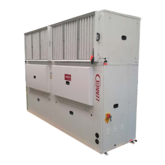
- Page 1 INSTALLATION, OPERATING AND MAINTENANCE VERTICAL PACKAGED AIR CONDITIONER COMPACTAIR 8 - 85 kW COMPACTAIR ADV IOM- MIL157E-0218-04/2018 www.lennoxemea.com...
-
Page 2: Table Of Contents
The manufacturing of these units is made under the requirements of the ISO 9001 and ISO 14001. All the information contained in this manual, including any drawing and technical descriptions provided by us, remain the property of Lennox and must not be used (except in the operation of this product), reproduced, issued to or made available to third parties without the prior written agreement of Lennox. -
Page 3: Points To Bear In Mind
All technical data contained in these operating instructions, including the diagrams and technical description remains the property of Lennox and may not be used (except for the purpose of familiarizing the user with the equipment), reproduced, photocopied, trans- ferred or transmitted to third parties without prior written authorization from Lennox. -
Page 4: Data Page For Commissioning Unit
D ATA PAGE FOR UNIT COMMISSIONING UNIT: SERIAL Nr: CONTROL PANEL IDENTIFICATION CODE: INSTALLATION ADDRESS: INSTALLER: INSTALLER TEL: INSTALLER ADDRESS: DATE OF COMMISSIONING: CHECKS: SUPPLY VOLTAGE: RATED VOLTAGE OF THE UNIT: UNIT ON SHOCK ABSORBERS DRAINAGE WITH TRAP MAIN POWER SUPPLY CONNECTION CONTROL PANEL CONNECTION COMPRESSOR OIL LEVEL INDICATOR DATA INPUT:... -
Page 5: General Characteristics
M: 400V/3/50 M: R-410A I: Indoor unit UNIT HEAT PUMP. Cooling capacity (kW) Heating capacity (kW) UNITS V/Ph/50 Hz PACKAGE CAMH025SM1M 400 V 3 Ph 17,9 22,4 15,2 19,6 CAMH035SM1M 400 V 3 Ph 13,0 26,4 32,4... -
Page 6: General Description
1.- GENERAL CHARACTERISTICS 1.2.- GENERAL DESCRIPTION. The vertical self-contained conditioners, Compactair Advanced range, in the heat pump version are air condensed units that have been designed for small commercial and residential installations. The units consist of two sections, an indoor section and an outdoor section, are units that by their design can be supplied in package and split version. They are designed for operation coupled to a network of air distribution ducts in indoor and outdoor sections. - Page 7 1.- GENERAL CHARACTERISTICS 1.2.- GENERAL DESCRIPTION. OPTIONS. Fresh air: Control and comunication: Kit Freecooling. Remote display DC for user. Return fan module. Service display DS. Filtration: Multi Unit Display DM. High effi ciency fi lter: M5+F7. Remote probe in environment. Auxiliary Heat : Modbus RS485 comunication interface.
-
Page 8: Physical Data
1.- GENERAL CHARACTERISTICS 1.3.- PHYSICAL DATA. CAMH025SM1M CAMH035SM1M CAMH045SM1M Cooling capacity (*) 22,4 32,4 Heating capacity (**) 19,6 29,5 42,2 Nominal absorbed power (Cold) (*) 13,2 Nominal absorbed power (Heating) (**) 12,9 18,8 DIMENSIONS Height 2145 2145 2145 Width 1445... - Page 9 1.- GENERAL CHARACTERISTICS 1.3.- PHYSICAL DATA. CAMH060DM1M CAMH075DM1M CAMH085DM1M Cooling capacity (*) 59,6 85,3 Heating capacity (**) 56,2 67,7 80,8 Nominal absorbed power (Cold) (*) 23,8 28,3 35,4 Nominal absorbed power (Heating) (**) 27,3 32,6 DIMENSIONS Height 2145 2145 2145 Width 2813 2813...
-
Page 10: Electrical Data
1.- GENERAL CHARACTERISTICS 1.4.- ELECTRICAL DATA. ELECTRICAL CONSUMPTIONS. CAMH025SM1M CAMH035SM1M CAMH035SM1M Voltage V/f (50 Hz) 400V/ 3Ph 400V/ 3Ph 400V/ 3Ph Total maximum power 13,9 18,6 24,5 Total maximum current 24,6 33,4 43,6 OUTDOOR UNIT CASH025SM1M CASH035SM1M CASH035SM1M 400V/ 3Ph... - Page 11 1.- GENERAL CHARACTERISTICS 1.4.- ELECTRICAL DATA. ELECTRICAL CONSUMPTIONS. CAMH060DM1M CAMH075DM1M CAMH085DM1M Voltage V/f (50 Hz) 400V/ 3Ph 400V/ 3Ph 400V/ 3Ph Total maximum power 35,3 40,8 46,8 Total maximum current 62,5 82,2 OUTDOOR UNIT CASH060DM1M CASH075DM1M CASH085DM1M Voltage V/f (50 Hz) 400V/ 3Ph 400V/ 3Ph 400V/ 3Ph...
-
Page 12: Operating Limits
1.- GENERAL CHARACTERISTICS 1.5.- OPERATING LIMITS. Operating Limits Maximum temperatures Minimum temperatures 32ºC BS / 23ºC BH 21ºC BS / 15ºC BH Indoor temperature Cooling Cycle Operation 48ºC -10ºC Outdoor temperature 24ºC BS 15ºC BS Indoor temperature Heating Cycle Operation 25ºC -12ºC Outdoor Temperature... -
Page 13: Fan Performances
1.- GENERAL CHARACTERISTICS 1.6.- FAN PERFORMANCES. INDOOR FANS (Nominal speed). CAMH025SM1M CAMH035SM1M CAIH025SM1M CAIH035SM1M Min Airfl ow Min Air Flow Min Airfl ow Min Air Flow Max Airfl ow Max Air Flow Max Airfl ow Max Air Flow Nom Reg... - Page 14 1.- GENERAL CHARACTERISTICS 1.6.- FAN PERFORMANCES. OUTDOOR FANS. CAMH025SM1M CAMH035SM1M CASH025SM1M CASH035SM1M Min Airfl ow Min Airfl ow Min Air Flow Min Air Flow Max Airfl ow Max Airfl ow Max Air Flow Max Air Flow Nominal Nominal Nom Reg...
-
Page 15: Refrigeration Drawings
1.- GENERAL CHARACTERISTICS 1.7.- HEAT PUMP PIPING DRAWINGS. CAMH025 & CAMH035 & CAMH045 PACKAGE UNITS PIPING DRAWINGS Compresor Scroll BLDC Ventilador PLUG FAN BS14 BS13 Válvula 4 vías Acumulador Ventilador Aspiración PLUG FAN Válvula expansión electrónica Filtro secador Válvula retención CASH/CAIH025 &... - Page 16 1.- GENERAL CHARACTERISTICS 1.7.- HEAT PUMP PIPING DRAWINGS. CAMH025 & CAMH035 & CAMH045 PACKAGE UNITS PIPING DRAWINGS Compresor Scroll BLDC Ventilador PLUG FAN BS14 BS13 Válvula 4 vías Acumulador Aspiración Válvula expansión electrónica Filtro secador Ventilador PLUG FAN Válvula retención Ventilador PLUG FAN Ventilador...
- Page 17 1.- GENERAL CHARACTERISTICS 1.7.- HEAT PUMP PIPING DRAWINGS. CASH/CAIH025 & CASH/CAIH035 & CASH/CAIH045 SPLIT UNITS PIPING DRAWINGS Compresor B13_1 Scroll BLDC Ventilador PLUG FAN BS13 BS14 BS13_1 Válvula 4 vías Separador de aceite Acumulador Aspiración Válvula expansión electrónica Filtro secador UNIDAD INTERIOR UNIDAD EXTERIOR Válvula expansión...
-
Page 18: Sound Levels
1.- GENERAL CHARACTERISTICS 1.8.- SOUND LEVELES. 1000 2000 4000 8000 dB(A) Indoor side in duct 49,9 54,5 63,7 66,3 63,9 61,2 61,9 60,4 Standard Outdoor side in duct 60,3 66,2 74,1 76,8 76,4 77,0 74,8 74,7 unit Outdoor side radiated 50,4 59,1 64,2... -
Page 19: Dimensions - Split Units
1.- GENERAL CHARACTERISTICS 1.9.- SPLIT UNITS DIMENSIONS. CAIH 025-035-045 1445 1265 TUBO DE DRENAJE M 3/4 G CABLE INTERCONEXIÓN UNIDAD EXTERIOR TUBO DE DRENAJE M 3/4 G ALIMENTACIÓN ELÉCTRICA CASH 025-035-045 1445 1171 1092 1093 TUBO DE DRENAJE M 3/4 G CABLE INTERCONEXIÓN UNIDAD INTERIOR ALIMENTACIÓN ELÉCTRICA... - Page 20 1.- GENERAL CHARACTERISTICS 1.9.- SPLIT UNITS DIMENSIONS. CAIH 060-075- 085 2814 1265 1265 1047 1047 CABLE INTERCONEXIÓN TUBO DE DRENAJE M 3/4 G UNIDAD EXTERIOR ALIMENTACIÓN ELÉCTRICA TUBO DE DRENAJE M 3/4 G 1043 1043 2813 CASH 060-075-085 2813 1092 1092 1171 1171...
-
Page 21: Dimensions - Packaged Units
1.- GENERAL CHARACTERISTICS 1.10.- PACKAGE UNITS DIMENSIONS. CAMH 025-035-045 1445 1265 TUBO DE DRENAJE M 3/4 G 1171 TUBO DE DRENAJE 1527 ALIMENTACIÓN ELÉCTRICA M 3/4 G 1497 1092 1380 TUBO DE DRENAJE M 3/4 G 2145 1092 ALIMENTACIÓN ELÉCTRICA CAMH 060-075-085 2814 1265... -
Page 22: Air Supply Confi Guration
1.- GENERAL CHARACTERISTICS 1.11.- AIR SUPPLY CONFIGURATIONS OPTIONAL EXECUTION STANDARD EXECUTION (TO BE CARRIED OUT BY THE INSTALLER) 1.11.- OPTIONS. FRESH AIR OPTIONS Free-cooling 1.- OPERATION. The control compares the values of temperature between outside air and room air by means of the probes; if there is a negative difference and the safety elements allow (discharge temperature probes) then the control acts on the servomotor, which opens the outside damper and closes the return damper, allowing cool outside air to enter the room. - Page 23 1.- GENERAL CHARACTERISTICS 1.11.- OPTIONS. FRESH AIR OPTIONS Return fan Fan return cabinet is supplied loose INDOOR UNIT 1 CIRCUIT 025-035-045 FILTRATION OPTIONS. High Effi ciency Filter: M5+F7. The fi lter is supplied loose and must be placed in the fan exit. HIGH EFFICIENCY FILTER: M5+F7 1267...
- Page 24 DM - Terminal to view time and zone settings. It is possible to confi gure until 7 time zones each day with 4 operating modes per zone. It can be confi gured with the DM or during installation by a Lennox technician. Communications: MODBUS / BACNET / LONWORKS.
- Page 25 1.- GENERAL CHARACTERISTICS 1.12- OPTIONS. ELECTRIC AND SECURING OPTIONS. Indoor air quality sensor. The indoor air quality is controlled with the CLIMATIC ™ main controller through a COV (volatile organic compound) sensor which detects the amount of CO2 in the air between 0 and 2000 ppm. (This value varies depending on the occu- pancy levels of the space).
-
Page 26: Installation
LENNOX Distribution Department and stating why the machine is unacceptable on the transport agent’s delivery note. Any later complaint or claim made to the LENNOX Distribution Department for this type of damage cannot be considered under the Guarantee. The modifi cations that the customer makes in the units will be under his responsibility and in this case, the declaration of conformity certifi... -
Page 27: Unit Location
2.- INSTALLATION 2.3.- UNIT LOCATION. - The bedplate is made up of two metal channels, capable of with standing the weight of the units whether hung from the ceiling or mounted on the fl oor. - If the unit is fl oor mounted, then the profi les should be isolated with shock absorbing material such as anti-vibration or pads. Place the anti-vibration to avoid any buckling. -
Page 28: Installation Clearances
2.- INSTALLATION 2.5.- INSTALLATION CLEARANCES. Clearance around the unit for service and maintenance. SERVICE SPACE Space should be left free for access or servicing, to ease the installation of ducts, drainage connections, electric installation and cleaning fi lters, as well as easy access to the unit. 1 m. -
Page 29: Cooling Connections
2.- INSTALLATION 2.7.- REFRIGERANT CONNECTIONS Split units are supplied with gas and liquid lines sealed with copper covers, and located 60mm from casing. Liquid Cupper cover Brazing Split units are supplied with nitrogen gas, which must be removed before carrying other operation and then proceed as follow. - Page 30 2.- INSTALLATION 2.7- REFRIGERANT CONNECTIONS To locate the outdoor and the indoor units, refer to the following information: OUTDOOR UNIT POSITION A : A syphon suction must be installed at the base of the vertical of the gas line, and syphons must be installed every 8 meters upward. The minimum speed suction must not be below 6m/s.
- Page 31 2.- INSTALLATION 2.7- REFRIGERANT CONNECTIONS In the double circuit units , check before connecting C1 and C2 circuits , that they are the same circuit for the indoor and the outdoor section TABLE 1: REFRIGERANT LINES SELECTION UNIT - MODEL UNIT -MODEL Position A Vertical line REFRIGERANT LINES...
-
Page 32: Electrical Connections
2.- INSTALLATION 2.8.- ELECTRICAL CONNECTIONS. - Before making the electrical connections, ensure that all circuit breakers are open. - To make the elctrical connections, follow the electrical diagram supplied with the unit. - Take into account the current standard for the installation of the unit, whether local, regional or national standards. - USE SUPERINMUNIZED DIFFERENTIAL SWITCHES. - Page 33 2.- INSTALLATION 2.8.- ELECTRICAL CONNECTIONS. - Before making the electrical connections, ensure that all circuit breakers are open. - To make the elctrical connections, follow the electrical diagram supplied with the unit. - Take into account the current standard for the installation of the unit, whether local, regional or national standards. - USE SUPERINMUNIZED DIFFERENTIAL SWITCHES.
-
Page 34: Terminal Connection
2.- INSTALLATION 2.9.- TERMINAL CONNECTION. 2.9.1.- TERMINAL CONNECTION WITH PACKAGE UNIT. ¡ IMPORTANT ! THE SHIELDED CONNECTING CABLE BETWEEN THE CONTROL PANEL AND THE UNIT MUST BE SEPARATED FROM ANY OTHER TYPE OF ELECTRICAL WIRING. CONNECT IT TO THE ELECTRIC PANEL LOCATED IN THE OUTDOOR UNIT. NOTES: - For securing and connecting the Control Panel, consult the control panel Manual supplied with the unit. - Page 35 2.- INSTALLATION 2.9.- TERMINAL CONNECTION. 2.9.2.- TERMINAL CONNECTION WITH SPLIT UNIT. ¡ IMPORTANT ! THE SHIELDED CONNECTING CABLE BETWEEN THE CONTROL PANEL AND THE UNIT MUST BE SEPARA- TED FROM ANY OTHER TYPE OF ELECTRICAL WIRING. CONNECT IT TO THE ELECTRIC PANEL LOCATED IN THE OUTDOOR UNIT.
-
Page 36: Commissioning And Operation
3.- COMMISSIONING AND OPERATION 3.1.- PRELIMINARY CHECKS BEFORE START UP. 1. Check that drain pipe connections, their fi xtures and that the level of the unit is tipped toward the drain. 2. Inspect the state of the ducts and grilles (clean and open grilles, no breaks in the duct, etc.). 3. -
Page 37: Preliminary Checks At Startup
3.2.- PRELIMINARY CHECKS DURING START UP. LENNOX REFAC, S.A. Designs and develops its machines always looking for the greater comfort and well-being of its customers and users, at the same time as the greater energy effi ciency of the elements that constitute the units. This effort would be fruitless if it was not united to a responsible use of these equipment. - Page 38 In order to maintain CE marking compliance, replace- must be reversed at the head of the main switch. ment of components shall be carried out using spare parts, or using parts approved by Lennox. Only the coolant shown on the manufacturer’s name- Refrigerating circuit(s):...
-
Page 39: Climatic™ Confi Guration
3.- COMMISSIONING AND OPERATION 3.3.- CLIMATIC™ CONFIGURATION Settings 1. Supply Air-fl ow adjustement (depending on customer requirements) a. 3333 = nominal air fl ow / pressure b. 3334 = reduced air fl ow / pressure 2. Scheduling (depending on customer requirements) a. - Page 40 3.- COMMISSIONING AND OPERATION Commissioning Check: 1. Airfl ow Vs Damper a. Test B.Nom100% : i. adjust the blower speed % (3333)to get the required air-fl ow ii. adjust the exhaust speed % (3864) to get the required air-fl ow b.
-
Page 41: Maintenance
4.- MAINTENANCE When carrying out maintenance works on these units, please make a correct segregation of the non-hazardous waste generated: insulation, air fi lters, plastic or metallic elements, packaging, etc., as well as waste considered hazardous: oils, fi lters and rags Impregnated with oils, welding elements such as fi ller material, strippers, electrical and electronic waste, batteries, lamps, etc., these must be managed by an authorized dealer. -
Page 42: Maintenance Plan
Wash and dry carefully. Replace Filter if necessary by an original • Clean or replace fi lters: Disposable, or metal frame. Lennox fi lter. Blocked fi lter will reduce the performance of the unit. THE UNIT SHOULD NEVER BE OPERATED WITHOUT FILTERS Visually check the oil level through the sight •... -
Page 43: Corrective Maintenance
4.- MAINTENANCE 4.3.- CORRECTIVE MAINTENANCE. IMPORTANT: MAKE SURE THAT THE UNIT IS FULLY DISCONNECTED FROM THE POWER SUPPLY WHEN CARRYING OUT ANY TYPE OF WORK ON THE MACHINE. If any component in the cooling circuit is to be replaced, follow these recommendations: - Always use original replacement parts. -
Page 44: Failure Diagnosis
4.- MAINTENANCE 4.4.- FAILURE DIAGNOSIS. In case of failure or malfunction of the unit, the display on the control panel will show an error or alarm warning which is explained in the control panel manual. Nevertheless, whenever there is a unit fault, the unit should be shut down and our service technicians consulted. Fault Possible causes Possible solutions... - Page 45 NOTES Installation Manual • COMPACTAIR ADV IOM-MIL157E-0418 • 44 •...
- Page 46 NOTES Installation Manual • COMPACTAIR ADV IOM-MIL157E-0418 • 45 •...
- Page 47 NOTES Installation Manual • COMPACTAIR ADV IOM-MIL157E-0418 • 46 •...
- Page 48 +33 4 72 23 20 20 LENNOX DISTRIBUTION +33 4 72 23 20 20 Due to LENNOX EMEA ongoing commitment to quality, the specifi cations, ratings and dimensions are subject to change without notice and without incurring liability. COMPACTAIR ADV IOM- Improper installation, adjustment, alteration, service or maintenance can cause property damage or personal injury.
Need help?
Do you have a question about the CAMH025SM1M and is the answer not in the manual?
Questions and answers