Advertisement
Table of Contents
- 1 Table of Contents
- 2 Unit Dimensions
- 3 Specifications / Electrical Data
- 4 Model Number Information
- 5 Adjusting the BDC3 Blower Control
- 6 Adjusting the Blower Speed
- 7 I Application
- 8 Unit Components
- 9 Optional Electric Heat
- 10 Configuration Modification
- 11 Electrical Connections
- 12 Wiring Diagrams
- 13 Performance Checklists
- 14 Sequence of Operations
- Download this manual
Service Literature
WARNING
Improper installation, adjustment, alteration, service or
maintenance can cause personal injury, loss of life, or
damage to property.
Installation and service must be performed by a licensed
professional installer (or equivalent) or a service agency.
CAUTION
Physical contact with metal edges and corners while
applying excessive force or rapid motion can result in
personal injury. Be aware of, and use caution when
working near these areas during installation or while
servicing this equipment.
WARNING
The Clean Air Act of 1990 bans the intentional venting of
refrigerant (CFCs, HCFCs and HFCs) as of July 1, 1992.
Approved methods of recovery, recycling or reclaiming
must be followed. Fines and/or incarceration may be
levied for noncompliance.
INSTALLATION AND SERVICE PROCEDURE
Corp. 1323-L6
August 2018
CBX25UHV Series
Page 1
Table of Contents
. . . . . . . . . . . . . . . . . . . . . . . . . . . .
. . . . . . . . . . . . . . . . . . . . . . . . . . . . . . .
. . . . . . . . . . . . . . . . . . . . . . . . .
. . . . . . . . . . . . . . . . . . . . . . . . .
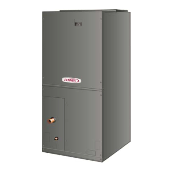
The CBX25UHV series units are high efficiency blower coils.
Several models are available in sizes ranging from 1-1/2
through 5 tons. The CBX25UHV is designed for HFC-410A
refrigerant only.
CBX25UHV series units are designed to be matched with the
13SEER air conditioner and heat pump line, but can be
matched with other air conditioners or heat pumps as noted in
the rating information. See Product Specification bulletin.
The CBX25UHV air handler is designed for indoor
installation only. The unit comes ready to install in either
up-flow
or
horizontal
modifications are required for right-hand air discharge
applications. Electric heat and other accessories are
available and are listed in the CBX25UHV Product
Specification bulletin.
IMPORTANT
On some pans, the primary (main) and secondary drain
holes have knockouts.
Confirm primary (main) and secondary drains are open.
IMPORTANT INFORMATION TO INSTALLER
The thermostatic expansion valve (TEV) with check
valve sensing bulb is shipped inside the unit cabinet.
This sensing bulb must be re-installed in a proper
location outside of the cabinet. See page 22 for details.
Information contained in this manual is intended for use by
experienced
HVAC
service
specifications are subject to change. Procedures outlined
in this manual are presented as a recommendation only
and do not supersede or replace local or state codes.
CBX25UHV
2
. . . . . . . . . . . . . . . . . . .
5
. . . . . . . . . . . . . . . .
3
. . . . . . . . . . . .
5
. . . . . . . . . . . . . . . . . .
5
10
10
. . . . . . . . . . . . . . . . . . . .
13
. . . . . . . . . . . . . . . .
17
. . . . . . . . . . . . . . . . . . . .
26
28
. . . . . . . . . . . . . . . . . .
29
. . . . . . . . . . . . . . . . .
29
left-hand
applications.
technicians
only.
Field
All
Advertisement
Table of Contents

Related Manuals for Lennox CBX25UHV Series


Summary of Contents for Lennox CBX25UHV Series
-
Page 1: Table Of Contents
5 tons. The CBX25UHV is designed for HFC-410A refrigerant only. CAUTION CBX25UHV series units are designed to be matched with the 13SEER air conditioner and heat pump line, but can be Physical contact with metal edges and corners while... -
Page 2: Unit Dimensions
CBX25UHV Unit Dimensions – Upflow – inches (mm) 3/4 (19) LINE VOLTAGE Right, Left and Top LOW VOLTAGE Right Side Only AIR FLOW CONDENSATE DRAIN PIPING PLATE (4) (2−1/4 x 3−3/4) FILTER ACCESS SUCTION LINE LIQUID LINE (19) (Opening) (Opening) 1−3/4 2−1/2 2−1/2... -
Page 3: Specifications / Electrical Data
CBX25UHV Unit Dimensions – Horizontal – inches (mm) −024 −030 −036 −042 −048 / −060 −018 Dimension inches inches inches inches inches inches 40−1/2 1029 1092 1219 1219 52−1/2 1334 18−1/2 18−1/2 21−7/8 21−7/8 21−7/8 12−1/4 6−1/4 6−3/8 18−7/8 17−7/8 15−1/4 3−5/8 5−1/2... - Page 4 SPECIFICATION General Model Number CBX25UHV018 CBX25UHV024 CBX25UHV030 CBX25UHV036 Data Nominal tonnage Connections Suction/Vapor line (o.d.) in. sweat Liquid line (o.d.) in. sweat Condensate in. fpt (2) 3/4 (2) 3/4 (2) 3/4 (2) 3/4 Indoor 3.11 3.56 4.00 4.89 Net face area ...
-
Page 5: Model Number Information
MODEL NUMBER IDENTIFICATION CB X 25 UHV - 030 - 230 - 1 Unit Type Minor Revision Number CB - Air Handler Voltage Refrigerant Type 230 = 208/230V-1 phase-60hz X = HFC-410A Nominal Cooling Capacity Series 018 = 1.5 tons 024 = 2 tons Configuration 030 = 2.5 tons... - Page 6 JUMPER SETTINGS Table 1 lists the factory blower speed tap settings for ADJUST JUMPER CBX25UHV series units. These settings are for nominal The ADJUST pins allow the motor to run at normal speed, tonnage match-ups with the CBX25UHV. When matched...
- Page 7 ® ..Lennox Harmony III Zone Control Applications - Minimum air handler speed is approximately 250 cfm . Table 3. CBX25UHV‐024 Air Handler Performance (0 through 0.80 in. w.g. External Static Pressure Range)
- Page 8 Continuous fan speed is approximately 50% of second-stage COOL speed setting. ® ..Lennox Harmony III Zone Control Applications - Minimum air handler speed is approximately 450 cfm. Table 8. CBX25UHV‐060 Air Handler Performance (0 through 0.80 in. w.g. External Static Pressure Range)
- Page 9 Table 10. CBX25UHV, Thermostat and Two‐Stage Outdoor Unit Operating Sequence Operating Sequence System Demand System Response Thermostat Demand Relative Humidity Handler System Com Condition Status pressor Step (COOL) Comments NO CALL FOR DEHUMIDIFICATION Normal Operation - Acceptable 24 VAC Compressor and indoor air handler follow thermo...
-
Page 10: I Application
Once demand is met, motor runs at 50% for 30 B-Transformer seconds. All CBX25UHV series units use a single line voltage to After 30 seconds at 50%, motor ramps down to 24VAC transformer mounted in the control box. The stop. - Page 11 Wait give minutes minimum after turning off power to allow capacitors to discharge. PRIMARY SECONDARY It is normal for a variable speed motor to gently rock back ORANGE BLUE and forth at the beginning of operation. During this time period the solidstate controller is determining the exact 240 VOLTS position of the rotor.
- Page 12 ™ An option for Test 2 is to use the TECMatePRO service tool (Lennox catalog number X2655) with the 16-pin plug in to apply 24V to the pins. Figure 10. Testing Motor Windings (Line to Ground) Using this tool eliminates the risk of applying power to the Test 3: Testing Motor Windings (Winding to wrong pins.
-
Page 13: Optional Electric Heat
2. Set the meter to the lowest ohms scale. NOTE - When the unit is installed in horizontal applications, a secondary drain pan is recommended. Refer to local If the readings are all less than 20 ohms and within +/ 10% codes. - Page 14 Before installing the unit, check information on the unit should then line up with holes in the air handler control rating plate to ensure that the unit meets the job box. specification, proper electrical power is available, and that 6. Secure the electric heater assembly with the screws proper duct clearances are maintained.
- Page 15 B-Changing Circuit Breaker Orientation NOTE - There may be only one clip securing each The air handler comes from the factory setup for horizontal circuit breaker. left-hand discharge which requires no change in the circuit breaker orientation. However, if the air handler is installed in BREAKER(S) a horizontal right-hand discharge position, rotate the MOUNTING...
- Page 16 shows L1, L2 and ground GND connections for a 2-breaker configuration. 208/240 VOLT FIELD SUPPLY WIRES CIRCUIT 1 CIRCUIT 2 Field Supply Ground Wires CIRCUIT BREAKERS Figure 18. Field Power Supply Wiring Heaters equipped with terminal blocks—Connect CIRCUIT BREAKERS KNOCKOUTS field power supply wiring to terminal block(s).
-
Page 17: Configuration Modification
WARNING HORIZONTAL DRAIN PAN Confirm air tight seal between breaker cover and air IMPORTANT! REMOVE PAN FOR BEST EFFICIENCY handler access panel. Apply a thin silicone bead to the AND AIR FLOW. adhesive back seat to ensure air tight seal. Failure to seal circuit breaker cover will allow warm moist air to be pulled into control panel which can create condensation to form on the circuit breaker and other... - Page 18 3. Set unit so that it is sloped toward the drain pan end of the unit (see figure 30). 4. The horizontal configuration is shown in figure 24. REMOVE BRACKETS AIR FLOW SECURING BOTH DRAIN PANS TO Drains UNIT. LEFT‐HAND DRAINS KNOCKOUT Figure 24.
- Page 19 C-Condensate Drain IMPORTANT On units of this type, where the blower “draws” rather than “blows” air through the coil, traps must be installed in the condensate drain lines (primary and auxiliary, if used). Traps prevent the blower from drawing air through the drain lines into the air supply.
- Page 20 INSTALL CONDENSATE DRAIN NOTE - When installing drain line connection fittings to the drain pan, hand tighten the fitting and use a thread The air handler is equipped with ¾” NPT condensate drain sealant. Over-tightening fittings split connections. connections on the drain pan. IMPORTANT 4.
- Page 21 TRAPS MUST BE DEEP ENOUGH TO OFFSET MAXIMUM STATIC DIFFERENCES — GENERALLY, TWO INCHES (51MM). TRAP DEPTH TO APPROVED LENNOX P-TRAP 49P66 REQUIRES A LARGER INSTALLATION SPACE THAN THE J-TRAP 91P90. DRAIN FOR NEGATIVE PRESSURE COILS (BLOWER DRAIN LINE SHOULD PIPE NIPPLE PROVIDED IN BAG ASSEMBLY - SCH 80, 3/4”...
- Page 22 D-Duct System and Filters E-Connecting Refrigerant Lines Refrigerant lines must be connected by a qualified DUCT SYSTEM technician in accordance with established procedures. The air handler is provided with flanges for the connection of the supply plenum. IMPORTANT Supply and return duct system must be adequately sized to meet the system's air requirements and static pressure Refrigerant lines must be clean, dry, refrigerant-grade capabilities.
- Page 23 NOTE - When installing refrigerant lines longer than 50 feet, 7. Allow refrigerant pipes to cool to room temperature. see the Lennox Refrigerant Piping Design and Fabrication 8. Re-install the expansion valve sensing bulb onto the Guidelines, CORP. 9351-L9, or contact Lennox Technical suction line outside of the cabinet.
- Page 24 PLEASE READ IMPORTANT ISSUES CONCERNING BRAZING OPERATIONS ON PREVIOUS PAGES BEFORE PROCEEDING. NOTE - REFER TO OUTDOOR UNIT INSTALLATION INSTRUCTIONS FOR REFRIGERANT PIPING SIZE REQUIREMENTS. NOTE - Use silver alloy brazing rods with five or six percent minimum silver alloy for copper-to-copper brazing, 45 percent alloy for copper-to-brass and copper-to-steel brazing.
- Page 25 Step 1. Remove unit access panels. Step 2. Locate and remove TEV sensing bulb from factory location. TEV SENSING BULB FACTORY REMOVE LOCATION ACCESS PANELS Step 3. Relocate TEV sensing bulb to Step 4. Properly position TEV sensing bulb external suction line. on suction line and fasten bulb to line.
-
Page 26: Electrical Connections
F-Sealing the Unit WARNING Seal the unit so that warm air is not allowed into the cabinet. Electric shock hazard! Can cause injury Warm air introduces moisture, which results in water or death. blow-off problems. This is especially important when the unit is installed in an unconditioned area. - Page 27 WARNING 208 / 240 VOLT TRANSFORMER USE COPPER CONDUCTORS ONLY PRIMARY SECONDARY 1. Disconnect all power supplies. 2. Remove the air handler access panel. 3. Route the field supply wires to the air handler electrical 240 Volts connection box. 208 Volts 4.
-
Page 28: Wiring Diagrams
VI-WIRING DIAGRAM Figure 37. Low Voltage Connections (Variable-Speed Motor) - Field Wiring Page 28... -
Page 29: Performance Checklists
VII-PERFORMANCE CHECKLISTS Installing Contractor’s Name_______________________ Installing Date_______________________________ Installing Contractor’s Phone_______________________ Air Handler Model #___________________________ Job Address____________________________________ Thermostat Line Voltage SUPPLY Disconnect Switch Integrated Control Temperature Duct Blower Motor Amps System Electric Heat Amps Duct Static RETURN Filter Drain Line DUCT SYSTEM TOTAL EXTERNAL STATIC (dry coil) dry coil wet coil... - Page 30 Installing Contractor’s Name_______________________ Installing Date_______________________________ Installing Contractor’s Phone_______________________ Air Handler Model #___________________________ Job Address____________________________________ Line Voltage Disconnect Switch Thermostat Integrated Control Duct System Duct System Filter RETURN SUPPLY Electric Heat Amps Blower motor Amps Drain Line Duct Static Temperature DUCT SYSTEM TOTAL EXTERNAL STATIC (dry coil) dry coil wet coil...
- Page 31 VIII-SEQUENCE OF OPERATIONS Heat Pump Heating — On a call for heat pump heating, the Heating -- First-Stage Electric Heat with Conventional room thermostat sends a 24VAC signal from terminal Y1 to Thermostat — On a call for heating, the room thermostat pin 6 on the blower motor (a field-provided jumper connects sends a 24VAC signal to the air handler terminal W1.
Need help?
Do you have a question about the CBX25UHV Series and is the answer not in the manual?
Questions and answers