Lennox CBX25UH Series Installation And Service Procedure
Hide thumbs
Also See for CBX25UH Series:
- Installation instructions manual (21 pages) ,
- Installation and service procedure (22 pages) ,
- Installation instructions manual (16 pages)
Advertisement
Table of Contents
- 1 Table of Contents
- 2 Unit Dimensions
- 3 Specifications / Electrical Data
- 4 Model Number Information
- 5 Blower Data
- 6 Application
- 7 Unit Components
- 8 Optional ECB25 Electric Heat
- 9 Configuration Modification
- 10 Electrical Connections
- 11 Wiring Diagrams
- 12 Start-Up Operations
- 13 Sequence of Operations
- 14 Performance Checklists
- Download this manual
Service Literature
WARNING
Improper installation, adjustment, alteration, service or
maintenance can cause personal injury, loss of life, or
damage to property.
Installation and service must be performed by a licensed
professional installer (or equivalent) or a service agency.
CAUTION
As with any mechanical equipment, contact with sharp
sheet metal edges can result in personal injury. Take care
while handling this equipment and wear gloves and pro
tective clothing.
IMPORTANT
The Clean Air Act of 1990 bans the intentional venting of
refrigerant (CFCs, HCFCs and HFCs) as of July 1, 1992.
Approved methods of recovery, recycling or reclaiming
must be followed. Fines and/or incarceration may be
levied for noncompliance.
INSTALLATION AND SERVICE PROCEDURE
Corp. 1504-L6
September 2018
CBX25UH (-10) Series
Page 1
Table of Contents
. . . . . . . . . . . . . . . . . . . . . . . . . . . .
. . . . . . . . . . . . . . . . . . . . . . . . . . . . . . . .
. . . . . . . . . . . . . . . . . . . . . . . . . . . . . . . . .
. . . . . . . . . . . . . . . . . . . . . . . . . . . .
. . . . . . . . . . . . . . . . . . . . . .
. . . . . . . . . . . . . . . . . . . . . . . . . . .
. . . . . . . . . . . . . . . . . . . . . . . .
. . . . . . . . . . . . . . . . . . . . .
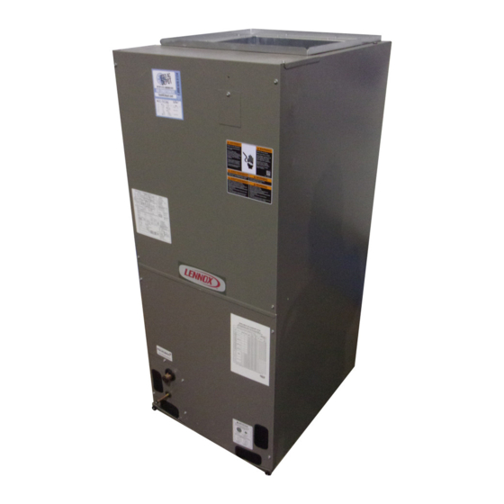
The CBX25UH units are high-efficiency air handlers. Several
models are available in sizes ranging from 1-1/2 through
5-tons. The CBX25UH is designed for HFC-410A refrigerant.
CBX25UH series units are designed to be matched with either
a 13 SEER air conditioner or heat pump, but can be matched
with other air conditioners or heat pumps as noted in the rating
information. See Product Specification bulletin.
This air handler is designed for indoor installation only. As
shipped, the unit is ready for installation in either upflow or
horizontal left-hand. Field modifications are required for
right-hand air discharge applications. Electric heat, down
flow air discharge application kits, air filters and other
various accessories are available and listed in the
CBX25UH Product Specification bulletin for ordering.
All units come with a factory installed check/expansion
valve.
Information contained in this manual is intended for use by
experienced licensed HVAC service technicians only. All
specifications are subject to change. Procedures outlined in
this manual are presented as a recommendation only and do
not supersede or replace local or state codes.
CBX25UH (-10)
2
. . . . . . . . . . . . . . . .
3
. . . . . . . . . . . . . . . . . . .
4
4
6
6
. . . . . . . . . . . . . . . . .
7
. . . . . . . . . . . . . . . . . . .
10
16
18
20
. . . . . . . . . . . . . . . . . . . .
21
22
© 2018 Lennox Industries Inc.
Advertisement
Table of Contents

Related Manuals for Lennox CBX25UH Series


Summary of Contents for Lennox CBX25UH Series
-
Page 1: Table Of Contents
1‐1/2 through 5-tons. The CBX25UH is designed for HFC-410A refrigerant. CAUTION CBX25UH series units are designed to be matched with either a 13 SEER air conditioner or heat pump, but can be matched As with any mechanical equipment, contact with sharp with other air conditioners or heat pumps as noted in the rating sheet metal edges can result in personal injury. -
Page 2: Unit Dimensions
CBX25UH Unit Dimensions – Upflow – inches (mm) 52-1/2 1334 NOTE - Unit is shipped configured for horizontal left-hand air discharge. Unit may be converted to horizontal right-hand air discharge by repositioning horizontal drain pan. Dimensions remain the same in all configurations. Page 2... -
Page 3: Specifications / Electrical Data
Specification and Electrical Data SPECIFICATION General Model Number CBX25UH018 CBX25UH024 CBX25UH030 CBX25UH036 Data Nominal tonnage Connections Suction/Vapor line (o.d.) in. sweat Liquid line (o.d.) in. sweat Condensate in. fpt (2) 3/4 (2) 3/4 (2) 3/4 (2) 3/4 Indoor 3.11 3.56... -
Page 4: Model Number Information
Model Number Identification CB X 25 UH − 030 − 230 − 10 Unit Type Minor Revision Number CB - Air Handler Voltage Refrigerant Type 230 = 208/230V-1 phase-60hz X = HFC-410A Nominal Cooling Capacity Series 018 = 1.5 tons 024 = 2 tons Configuration 030 = 2.5 tons... - Page 5 Table 1. Blower Performance (3-Speed PSC) - 240V (CFM @ ESP. - in. W. C.) Air Handler Blower Speed .10" WC .20" WC .30" WC .40" WC .50" WC Model Low (Red) Med (Blue) High (Black) Low (Red) Med (Blue) High (Black) 1130 1100...
-
Page 6: Application
TRANSFORMER BLOWER ASSEMBLY All CBX25UH series units use a single line voltage to 24VAC transformer mounted in the control box. The transformer supplies power to the control circuits in the indoor and outdoor unit. Transformers are rated at 40VA. -
Page 7: Optional Ecb25 Electric Heat
Optional ECB25 Electric Heat OFFSET The electric heat sections provide field installed electric heat for air handler units. Table 2 shows the available heat sections. Refer to the Product Specifications for heat section applications. Table 2. Electric Heat Sections Catalog Termination Type Part Number Number... - Page 8 7. The air handler access panels have knockouts over the require no change (see figure 9). To change the circuit breaker opening. Knock out both plates to applicable circuit breakers orientation for right-hand accommodate the circuit breaker levers. If installing a discharge, proceed to step 2.
- Page 9 3. Flip the breaker so that the wires attached to the circuit in accordance with tables 310-16 and 310-17 in the breakers terminals are on the left side (see figure 9). National Electric Code, ANSI/NFPA No. 70 or tables 1 through 4 in the Canadian Electric Code, Part I, CSA 4.
-
Page 10: Configuration Modification
CIRCUIT BREAKER COVER INSTALLATION 3. Set the thermostat to desired setting. 1. Remove any installed patch plates still present . 4. Affix the wiring diagram sticker to air handler scroll, aligned with circuit breaker unit wiring diagram sticker. 2. Remove paper covering adhesive back around backside perimeter of circuit breaker cover (figure 13). - Page 11 HORIZONTAL APPLICATION 5. If the unit is suspended, the entire length of the cabinet must be supported. If you use a chain or strap, use a IMPORTANT piece of angle iron or sheet metal attached to the unit (either above or below) to support the length of the cabinet.
- Page 12 Figure 21. Reinstall the Top Cap. Brackets Must Cover the Hairpins 6. Slide coil assembly, bottom drain pan and horizontal drain pan as one unit back into the air handler. Figure 19. Remove Coil Assembly, Bottom Drain Pan and Horizontal Drain Pan as a Unit 4.
- Page 13 7. Reinstall the brackets that hold the coil and horizontal 8. Reinstall the blower and coil access panels. drain pan in place. See figure 23. Figure 23. Reinstall Brackets that Hold the Coil and Horizontal Drain Pan in Place Page 13...
- Page 14 TRAPS MUST BE DEEP ENOUGH TO OFFSET MAXIMUM STATIC DIFFERENCES — GENERALLY, TWO INCHES (51MM). TRAP DEPTH TO APPROVED LENNOX P-TRAP 49P66 REQUIRES A LARGER INSTALLATION SPACE THAN THE J-TRAP 91P90. DRAIN FOR NEGATIVE PRESSURE COILS (BLOWER DRAIN LINE SHOULD PIPE NIPPLE PROVIDED IN BAG ASSEMBLY - SCH 80, 3/4”...
- Page 15 INSTALL CONDENSATE DRAIN DUCT SYSTEM The air handler is provided with flanges for the connection 1. Remove the appropriate drain knockouts. If necessary, of the plenum and ducts. The air handler is equipped with remove the indoor coil assembly from the cabinet. flanges that can form a filter rack for the installation of the air 2.
-
Page 16: Electrical Connections
7. Make sure outdoor unit has been put in place according WARNING to the Installation Instructions and is connected to the refrigerant lines. Electric Shock Hazard. SEALING THE UNIT Can cause injury or death. Seal the unit so that warm air is not allowed into the cabinet. Foil‐faced insulation has conductive characteristics sim... - Page 17 208 VOLT CONVERSION 1. Disconnect all power supplies. 2. Remove the air handler access panel. 3. Using the wiring diagram located on the unit access panel as a reference, move the 2 connected black transformer leads from the 240 volt terminal on the transformer to the 208 volt terminal on the transformer.
-
Page 18: Wiring Diagrams
Wiring Diagrams THERMOSTAT AIR HANDLER THERMOSTAT AIR HANDLER NOTE NOTE HEAT‐ONLY APPLICATION CONDITIONER THERMOSTAT HEAT PUMP UNIT UNIT AIR HANDLER COOLING‐ONLY APPLICATION THERMOSTAT AIR HANDLER CONNECT COMMON WIRE ONLY IF REQUIRED (REFER TO THE APPROPRIATE THERMOSTAT INSTALLATION INSTRUCTIONS) NOTE HEAT PUMP APPLICATION WITH AIR CONDITIONER ELECTRIC HEAT UNIT... - Page 19 THERMOSTAT AIR HANDLER CONDENSING UNIT Air Handler THERMOSTAT HEAT PUMP UNIT AIR HANDLER CONNECT COMMON WIRE ONLY IF REQUIRED (REFER TO THE APPROPRIATE S23 OUTDOOR THERMOSTAT THERMOSTAT INSTALLATION (IF USED) INSTRUCTIONS) K22 EM HEAT RELAY Heat Pump Application With Electric Heat Figure 28.
-
Page 20: Start-Up Operations
Figure 29. Unit Wiring Diagram - Electric Heat and Air Handler Has the condensate line been properly sized, run, Start-Up Operation trapped, pitched, and tested? Is the duct system correctly sized, run, sealed, and NOTE - Refer to outdoor unit installation instructions for insulated? system start-up instructions and refrigerant charging Have all cabinet openings and wiring been sealed? -
Page 21: Sequence Of Operations
At the completion of the cooling demand the indoor blower Are all access panels in place and secure? and outdoor unit should cycle off. Air handler should cycle CHECK BLOWER OPERATION off 45 seconds after the outdoor unit shuts off. Set thermostat to FAN ON. -
Page 22: Performance Checklists
Performance Checklists Installing Contractor’s Name_______________________ Installing Date_______________________________ Installing Contractor’s Phone_______________________ Air Handler Model #___________________________ Job Address____________________________________ Thermostat Line Voltage SUPPLY Disconnect Switch Integrated Control Temperature Duct Blower Motor Amps System Electric Heat Amps Duct Static RETURN Filter Drain Line DUCT SYSTEM TOTAL EXTERNAL STATIC (dry coil) dry coil wet coil... - Page 23 Installing Contractor’s Name_______________________ Installing Date_______________________________ Installing Contractor’s Phone_______________________ Air Handler Model #___________________________ Job Address____________________________________ Line Voltage Disconnect Switch Thermostat Integrated Control Duct System Duct System Filter RETURN SUPPLY Electric Heat Amps Blower motor Amps Drain Line Duct Static Temperature DUCT SYSTEM TOTAL EXTERNAL STATIC (dry coil) dry coil wet coil...
Need help?
Do you have a question about the CBX25UH Series and is the answer not in the manual?
Questions and answers