Lennox CB29M Installation Manual

Lennox CB29M Installation Manual

Elite series multi-position blower coils

Advertisement

E2005 Lennox Industries Inc.
Dallas, Texas, USA
IMPORTANT
For downflow application, kit number 83M57
(LB−109844A) is required. Kit is not provided with
coil blower; order separately.
IMPORTANT
The Clean Air Act of 1990 bans the intentional vent-
ing of refrigerant (CFC's and HCFC's) as of July 1,
1992. Approved methods of recovery, recycling or
reclaiming must be followed. Fines and/or incar-
ceration may be levied for noncompliance.
WARNING
Product contains fiberglass wool.
Disturbing the insulation in this product during
installation, maintenance, or repair will expose you
to fiberglass wool. Breathing this may cause lung
cancer. (Fiberglass wool is known to the State of
California to cause cancer.)
Fiberglass wool may also cause respiratory, skin,
and eye irritation.
To reduce exposure to this substance or for further
information, consult material safety data sheets
available from address shown below, or contact
your supervisor.
Lennox Industries Inc.
P.O. Box 799900
Dallas, TX 75379−9900
09/05
*2P0905*
INSTALLATION
INSTRUCTIONS
CB29M & CB30M
®
Elite
Series Units
MULTI−POSITION BLOWER COILS
504,719M
09/05
Supersedes 04/05
RETAIN THESE INSTRUCTIONS
FOR FUTURE REFERENCE

Table of Contents

. . . . . . . . . . . . . . . . . . . . . . . . . . . . . . . . . . . . . .
. . . . . . . . . . . . . . . . . . . . . . . . . . . . . . . . .
. . . . . . . . . . . . . . . . . . . . . . . . . . . . . . . . . . . .
. . . . . . . . . . . . . . . . . . . . . . . . . . . . . . . . . . . . . . . .
. . . . . . . . . . . . . . . . . . . . . . . . . . . . . . . . . . . . .
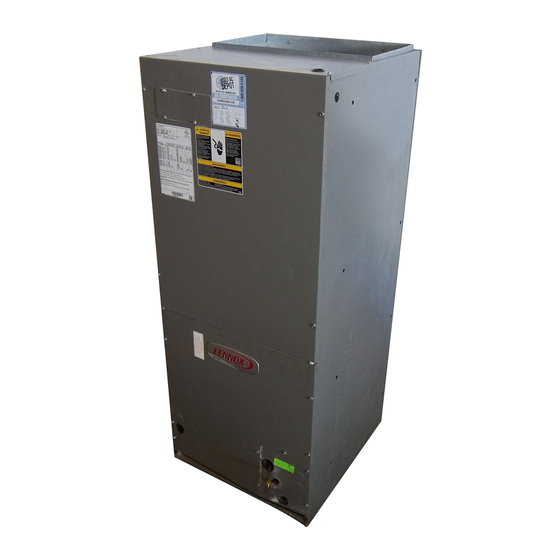
CB29M & CB30M Series Units
The Lennox CB29M and CB30M Elite
units are designed for installation with a matched remote
outdoor unit and optional field−installed electric heat. The
blower coil units are for indoor installation only.
The CB29M and CB30M units, designed for multi−position-
al installations, are completely assembled at the factory
and shipped ready for upflow or horizontal right−hand dis-
charge installation.

General

These instructions are intended as a general guide and do
not supersede local codes in any way. Consult authorities
having jurisdiction before installing the unit
Check equipment for shipping damage; if found, immedi-
ately contact the last carrier.
Shipping and Packing List
Each CB29M and CB30M unit package contains:
1 − Assembled blower coil unit
Page 1
. . . . . . . . . . . . . . . . . .
. . . . . . . . . . . . . . . . . . . . . . . .
. . . . . . . . . . . . . . . . . . . . . . .
. . . . . . . . . . . . . . . . . . . . . . .
. . . . . . . . . . . . . . . . . . . . . . .
. . . . . . . . . . . . . . . . . . . . . . . . . . . . .
. . . . . . . . . . . . . . . . . . . . . . . . . . . . . .
. . . . . . . . . . . . . . . . . . . . .
. . . . . . . . . . . . . . . . . . . . . . .
®
series blower coil
504,719M
*P504719M*
Litho U.S.A.
1
1
1
2
4
5
5
8
9
9
9
10
16
17

Advertisement

Table of Contents
loading

Summary of Contents for Lennox CB29M

  • Page 1: Table Of Contents

    The WARNING blower coil units are for indoor installation only. The CB29M and CB30M units, designed for multi−position- Product contains fiberglass wool. al installations, are completely assembled at the factory Disturbing the insulation in this product during and shipped ready for upflow or horizontal right−hand dis-...
  • Page 2: Cb29M Unit Dimensions

    CB29M Upflow and Downflow Unit Dimensions − inches (mm) PIPING PLATE DETAIL (19) (For upflow and downflow positions) SUPPLY AIR OPENING 1-1/8 (29) 4-3/8 (111) 5/8 (16) SUCTION LINE CONDENSATE DRAINS (2) (HORIZONTAL) (16) (16) (19) (51) LIQUID LINE 11-1/16...
  • Page 3 CB29M Horizontal Left− and Right−Hand Unit Dimensions − inches (mm) FILTER 5-3/8 (137) (51) LIQUID LINE SUCTION CONDENSATE LINE COIL DRAINS (2) BLOWER For dimensions A" (UPFLOW AND DOWNFLOW) through F", see 1-1/8 (29) chart on Page 2. CONDENSATE DRAINS (2)
  • Page 4: Cb30M Unit Dimensions

    CB30M Upflow and Downflow Unit Dimensions − inches (mm) PIPING PLATE DETAIL (19) (For upflow and downflow positions) SUPPLY AIR OPENING 1-1/8 (29) 4-3/8 (111) 5/8 (16) SUCTION LINE CONDENSATE DRAINS (2) (HORIZONTAL) (16) (16) (19) (51) LIQUID LINE 11-1/16 RETURN (281) CONDENSATE...
  • Page 5: Requirements

    End View Horizontal Position (Left-Hand Air Discharge) Requirements Installation Installation of Lennox blower coil units with or without op- WARNING tional electric heat must conform with standards in the Na- tional Fire Protection Association (NFPA) Standard for Improper installation, adjustment, alteration, ser-...
  • Page 6 14" from the floor for proper air re- Sheet Metal 4 in. (102 mm) turn. Lennox offers an optional upflow unit stand. 1/2 IN. SCREWS (45K31 for CB29M−21, −26, and −31; 45K32 for MAX. CB29M−41 through −65.) Upflow Configuration FRONT VIEW END VIEW...
  • Page 7 BACK COIL BEND END SEAL securing screws which are no longer than 1/2 inch to DRAIN PAN avoid damaging the coil or filter. Use sheet metal Figure 4 screws to connect the return and supply air plenums. Page 7 CB29M/CB30M SERIES...
  • Page 8: Field Piping Connections

    If electric heat section with circuit breakers (ECB29) L15 (sweat) series line sets as shown in Table 1 or use are applied to downflow CB29M or CB30M unit, cir- field−fabricated refrigerant lines. L10 (flare) line sets may cuit breakers must be rotated 180_ to the UP posi- be used by cutting off flare nut.
  • Page 9: Condensate Drain

    The following practices are recommended to ensure con- CB29M−41, −46, CB30M−31 20 x 20 (508 x 508) densate removal (see figures 8 and 9): CB29M−51, −65, CB30M−41, −46 20 x 22 (508 x 559) 1. Drain piping should not be smaller than the drain con- CB30M−51, −65 20 x 24 (508 x 610) nections at drain pan.
  • Page 10: Blower Speed Adjustments

    Blower Speed Tap Selection harness Minimum Blower Speeds (With Electric Heaters) connector For the minimum allowable speed for the CB29M/CB30M series units with electric heat, refer to the ECB29 installa- tion instructions. Air Volume Adjustment Blower speed selection is accomplished by changing the Press the tab to release wire connector.
  • Page 11 NOTE − All air data is measured external to unit with air filter in place. Electric heaters have no appreciable air resistance. Table 6 CB29M-41 Blower Performance (460V − 1 ph) Air Volume and Motor Watts at Specific Blower Taps...
  • Page 12 NOTE − All air data is measured external to unit with air filter in place. Electric heaters have no appreciable air resistance. Table 9 CB29M−51 Blower Performance (460V − 1 ph) Air Volume and Motor Watts at Specific Blower Taps...
  • Page 13 Table 11 CB29M−65 Blower Performance (460V − 1 ph) Air Volume and Motor Watts at Specific Blower Taps Medium High External Static Pressure in. w.g. Watts Watts Watts 1785 2050 2230 1055 1145 1775 2025 2200 1040 1135 1745 2005...
  • Page 14 Table 14 CB30M-41 Blower Performance (208/230V) Air Volume and Motor Watts at Specific Blower Taps Medium High External Static Pressure in. w.g. Watts Watts Watts 1120 1525 1150 1520 1005 1170 1510 1035 1180 1495 1055 1190 1475 1060 1185 1450 1050 1175...
  • Page 15 1690 1755 1425 1560 1620 1295 1415 1465 1140 1250 1290 1050 1160 1195 NOTE − All air data is measured external to unit with air filter in place. Electric heaters have no appreciable air resistance. Page 15 CB29M/CB30M SERIES...
  • Page 16: Electrical

    Table 20 CB30M-65 Blower Performance (460V − 1 ph) Air Volume and Motor Watts at Specific Blower Taps High External Static Pressure in. w.g. Watts Watts 1965 2140 1010 1950 2110 1930 2080 1910 2045 1880 2005 1850 1965 1815 1920 1735 1820...
  • Page 17: System Wiring Diagrams

    System Wiring Diagrams CB29 & CB30 Typical Wiring Diagram − Single Phase Figure 11 Page 17 CB29M/CB30M SERIES...
  • Page 18 CB29 & CB30 Typical Wiring Diagram − Three Phase Figure 12 Page 18 504719M 09/05...
  • Page 19 WHEN TWO−STAGE THERMOSTAT IS USED, CONNECT SECOND STAGE HEAT BULB TO TER- MINAL W2" AND REMOVE JUMPER BETWEEN TERMINALS R" AND W2." FACTORY INSTALLED JUMPERS L3 CONNECTION USED ON (Y−VOLTAGE) 3−PHASE ELECTRIC HEATERS ONLY. Figure 13 Page 19 CB29M/CB30M SERIES...
  • Page 20 Typical Field Wiring − Heat Pump Only Application LINE VOLTAGE FIELD INSTALLED CLASS 2 VOLTAGE FIELD INSTALLED NEC/CEC NOTE − ALL REMAINING WIRES ARE FACTORY INSTALLED TO EXTERNAL LOAD 24VAC AT .50 AMP MAXIMUM FACTORY INSTALLED JUMPERS Y2 USED ONLY WHEN TWO SPEED COMPRESSOR IS USED (HP21). CIRCUIT 1 USING SERVICE LIGHT OPTION (S54) WITH SOME ELECTRONIC THERMOSTATS MAY REQUIRE MOVING S54 COMMON WIRE TO Y1...

Table of Contents