Advertisement
Quick Links
User Manual
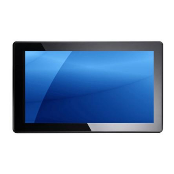
FPC 7161: 15.6" Industrial Fanless Multi-touch Panel PC with
Atom D2550 1.86GHz Processor
14628 Central Ave,
Chino, CA 91710
tel:909.597.7588, fax:909.597.1939
FPC 7161
Industrial Fanless Panel PC
© Copyright 2013 Acnodes, Inc.
All rights reserved. Product description and product specifications
are subject to change without notice. For latest product information,
please visit Acnodes' web site at www.acnodes.com.
Advertisement

Related Manuals for Acnodes FPC 7161


Summary of Contents for Acnodes FPC 7161
- Page 1 FPC 7161 Industrial Fanless Panel PC User Manual FPC 7161: 15.6” Industrial Fanless Multi-touch Panel PC with Atom D2550 1.86GHz Processor © Copyright 2013 Acnodes, Inc. 14628 Central Ave, All rights reserved. Product description and product specifications Chino, CA 91710 are subject to change without notice.
- Page 2 © Copyright 2013 Acnodes, Inc. All rights reserved. Product description and product specifications 14628 Central Ave, Chino, CA 91710 are subject to change without notice. For latest product information, tel:909.597.7588, fax:909.597.1939 please visit Acnodes’ web site at www.acnodes.com.
- Page 3 © Copyright 2013 Acnodes, Inc. 14628 Central Ave, All rights reserved. Product description and product specifications Chino, CA 91710 are subject to change without notice. For latest product information, tel:909.597.7588, fax:909.597.1939 please visit Acnodes’ web site at www.acnodes.com.
- Page 4 Table of Contents Disclaimers ..................ii Safety Precautions ................iii Chapter 1 Introduction .................1 General Description ..............1 Specifications ................2 Dimensions and Outliners .............4 I/O Outlets ................5 Packing List ................6 Chapter 2 Hardware and Installation.............7 CF card Installation ..............8 Open back cover ................9 Serial Ports Interface ..............11 2.3.1 COM1&COM2 Connector ..............11...
- Page 5 This chap ter contains ge neral inf orm atio n detaile d spe cifications FPC7161. Ch apter 1 in cludes the following sections: Gene ral Descrip tio n Spe cification Dimen sions z- - I/ O Outlets Packa ge List The FPC7161 adopts a 15 .6-inch W XGA TFT L CD with 300-nit brigh tness and an At om proce ssor D2 550 1.86 GH z to pro vide exce llent com puting p erformance and...
- Page 6 FPC71 61 has a PCI Expre ss Min i Card slot fo r o ptio nal ad d-ons such as wireless LAN card f or 802 .11 b/g co nnection s & 3G/ GPRS application, a nd more. It also provides an optiona l fixed rotational W LAN a ntenn a f or wirele ss n etwork connection.
- Page 7 Disk dr ive housing: One 2 .5” SATA Drive Net We ight: 5.0 Kgs (11.02 lb) Dimension: 396. 8x 53 .9x 24 7.1mm Oper ati on Temperature: -10C to 50C Relative Humidi ty: 1 0% t o 95% @ 4 0C, Non-Cond ensing Power Input: 10~30VDC with pho enix powe r connector...
- Page 8 The following diagrams sho w th e dim ension s and ou tlines of FPC 71 61...
- Page 9 Please re fer t o the follo wing illustra tion fo r I/O lo cat ions of the FPC7 161. POWER SWITCH (ATX) Termin al Blo ck for D C Power Input 2 x USB2.0 CO M 1 (RS-232/422/485) CO M 2 (RS-232) 2 x ETHERNET 2 x USB2.0 Audio (Line-Out)
- Page 10 FPC7161 unit x 1 Driver CD x 1 Phoenix connector x 1 Screws for HDD x 4 Panel mount k it x 6 If you cannot find the pack age or any items are missing, please contact Acnodes distributors immediately.
- Page 11 The FPC 7 161 provide s rich I/O ports a nd flexible expa nsions f or you to mee t different dema nd, for example CF card. Th e ch apter will show yo u how to install the hardware. It include s: CompactFlash Card ...
- Page 12 ™ The FPC7 161 provide s one CF slot f or u sers t o install CompactFla sh card. Please refer to the followin g instru ctions fo r installation: Step 1 Open the cover, unscrew 2 screws on the chassis Step 2 Stick the mylar on the CF card bottom side...
- Page 13 Step 3 Insert the CF card to the CF card slot, the finding the CF cover from the system package and screw it This se ction tells users how to o pen back cover. Please follow the steps below. Step 1 Unscrews on the back cover. Please refer the photo below...
- Page 14 Step 2 Remove the back cover...
- Page 15 The FPC 716 1 h as fo ur serial ports. COM 1 is RS-2 32/42 2/485 and COM2 is RS-232 . The fo llowin g ta ble shows you th e pin a ssignments o f this connector: RS-232 (D efault) C OM 1 RS-422 RS-485...
- Page 16 The pin assignme nt o f RS-232/RS-422/RS-485 is list ed o n the follo wing table. If yo u n eed COM1 port to suppo rt RS-4 22 or RS-485 mod e, ple ase ref er to Jump er Settings D ata- DC D D ata+...
- Page 17 There are 4 application options fo r the FPC 7161, Panel/Wall/De sktop/VESA mou ntin gs. The FPC716 1 provides VESA moun t: 100x100 mm . Screw four screws t o fix the kit in th e b ack chassis. The FPC7161 is de signed for pan el mou nt application. To m ount the FPC716 1,...
- Page 18 The FPC7161 provide s a convenient Ha rd Disk Drive (HD D) bracket for u sers to in sta ll 2.5 ” SATA HDD. Please follow th e ste ps: Step 1 Refer section 2.2 to open the back cover Step 2 Fix the HDD on the HDD tray by 4 screws...
- Page 19 Step 3 Plug the cables to connectors and screw the HDD tray on the bracket installation completes...
- Page 20 The FPC7161 pro vides one 2 04-pin DDR3 SODI MM socket t hat suppo rts syst em mem ory up to 4 GB. Please follow steps b elow to install the mem ory mod ule s: ? Ste p 1 Refer to section 2.2 to open the back cover Ste p 2 Find the DIMM heatsi nk on the back cover.
- Page 21 Step 3 Insert the DRAM to the DIMM socket, and then push it down firmly until it is clipped by the socket Installation completed...
- Page 22 The FPC71 61 provides one Mini card slot for user to install o ne wireless LAN card . When installing the wire less LAN card, refer to th e following instruction s and illust ration: Step 1 Refer to section 2.2 to open the back cover and find out mini-card slot on mainboard Step 2 Insert the wireless LAN card to the slot.
- Page 23 Step 3 F in d th e A nten n a c ab le and con n ect i t on wi rel ess L A N c ard Step 4 Lift the rubber stopper from the top of back cover and screw the antenna cable. ….
- Page 24 Step 5 Install the antenna on the antenna connector. FPC 7 161 equ ips with a phoen ix type powe r co nnector. It adopts 10VDC to 30VDC. Please follow the signs o n power co nnector to co nnect DC p ower source. Ё:Power neg ative +: Power p ositive G: Safty g rou nd...
- Page 25 This ch apter provides use rs with d etailed description how to set u p basic syste m con figuration through th e AMIBIOS8 BIOS se tup utility. To e nter the setup scree ns, follow t he st eps be low: Turn on t he co mpute r and press the <Del>...
- Page 26 When yo u first enter the Setup Utility, you will ente r the M ain setu p screen. You can a lways return to the Main setup screen by select ing the M ain tab. There a re two Main Se tup o ptio ns. They a re describ ed in th is sectio n.
- Page 27 This ite m can en able or disab le boo t o ptio n f or legacy ma ss storage de vice s with op tion ROM. The Advan ce d m enu also allows use rs to set configuratio n of the CPU and ot her system devices.
- Page 28 You can u se th is scre en to se lect options f or th e ACPI Con fig ura tion , an d cha nge the value of the selecte d o ptio n. A descript ion of th e select ed item ap pears on th e right side of th e screen.
- Page 29 This scree n sh ows the C PU Con figu ra tion , a nd you can ch ange the value of the se lected option. Use th is item to ena ble or d isable Hyper-Thre ading Te ch nology, which makes a sin gle physical processor perform m ulti-taskin g fu nct ion as two lo gical o nes.
- Page 30 The op tion al settings are: [Disa ble d]; [Ena bled ]. The optiona l settings are: [IDE]; [AHCI] .
- Page 31 Yo u can use this scre en to select options fo r the USB C onfiguratio n, and cha nge th e valu e of the selected option. A de scription of the sele cte d item ap pears o n the righ t side of the scre en. The optiona l settings are: [Auto];...
- Page 32 Yo u can u se th is screen to select optio ns fo r the Supe r IO Conf igu ration, and cha nge the value of t he selected op tio n. A descriptio n of the selected ite m appe ars on the righ t side of the screen Use this item to set paramet ers of seria l port 0~3...
- Page 33 This scre en shows the Hardware Health Co nfiguratio n, and a description of the selected item app ears on th e right sid e of the screen .
- Page 34 The Chipset m enu allows users to chang e the advanced chipset set tings. You can se lect an y of th e ite ms in the left frame of the screen to g o to the sub me nus: Ź...
- Page 35 This item is fo r memo ry freque ncy an d timin g settings. Press <En ter> to go to th e sub menu .
- Page 36 The Bo ot menu a llows u sers to cha nge boo t o ptions of t he syst em. Use this item to set numb er o f se con ds to wait for setup activation ke y. Use this ite m t o select th e p ower-on state for the Num Lock.. The optional settings a re: [On]; [Off].
- Page 37 The Se cu rity men u allows use rs to ch ange the securit y sett ings for the system. This ite m indica tes whet her an adm inistra tor passwo rd has been set. If the passw ord has been in sta lle d, Insta lled displays.
- Page 38 The Save & Exit me nu a llows users to load you r syste m configuration with o ptim al or fail-safe def ault values. When you have completed t he system configuration change s, select this option to leave Set up and rebo ot the compute r so th e new system co nfig uration param eters ca n ta ke effe ct.
- Page 39 Se lect this option to quit Se tup withou t making any permane nt changes to the system configuratio n. Se lect Discard Chan ges from th e Save & Exit men u and press <En ter>. Select Ye s to disca rd change s. It aut omatica lly sets all Set up o ptions to a comp lete set of def ault settings whe n you sele ct this option.
- Page 40 FPC7161 sup ports W indo ws 7 32 -bit. To facilitate the installatio n of system driver, please carefully re ad the instructions in this chapte r bef ore start installing. The FPC71 61 uses th e pro jected ca pacitive multi-tou ch . The sp ecification is liste d below.
Need help?
Do you have a question about the FPC 7161 and is the answer not in the manual?
Questions and answers