Table of Contents
Advertisement
Quick Links
PCA80XXX
User Manual
All rights reserved. Product description and product specifications are subject to change without notice.
For latest product information, please visit Acnodes' website at www.acnodes.com.
14628 Central Ave. Chino, CA 91710
© Copyright 2019 Acnodes Corp.
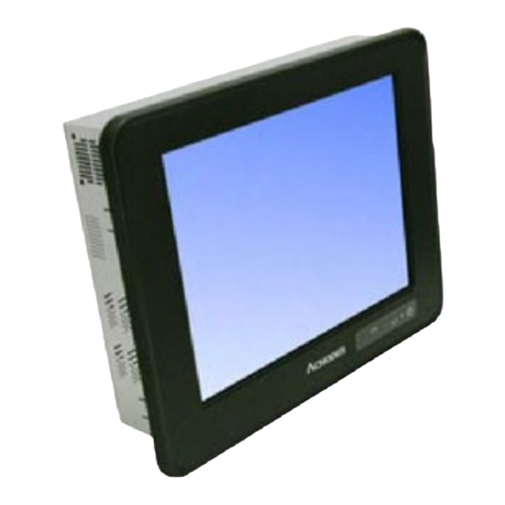
Expandable Industrial Touch Panel PC
1 x PCIe x1 + 1 x PCIe x16 Expansion Slots
Aluminum Die-Casting Front Bezel
1
Tel: 909.597.7588
Fax: 909.597.1939
Advertisement
Table of Contents

Related Manuals for Acnodes PCA80 Series


Summary of Contents for Acnodes PCA80 Series
- Page 1 Aluminum Die-Casting Front Bezel User Manual All rights reserved. Product description and product specifications are subject to change without notice. For latest product information, please visit Acnodes’ website at www.acnodes.com. 14628 Central Ave. Chino, CA 91710 Tel: 909.597.7588 Fax: 909.597.1939...
-
Page 2: Revision History
Revision History Reversion Date Description 2017/10/25 Official Version 2018/01/25 Modify PCIe information. Renew product images. 2018/06/01 Modify Core I 7 motherboard/BIOS chapter 2018/06/08 SW1-6 2019/01/02 Modify front bezel information 2019/10/25 Revise product images, dimensions and mechanical information... -
Page 3: Warning!/Disclaimer
Disclaimer This information in this document is subject to change without notice. In no event shall Acnodes Corporation be liable for damages of any kind, whether incidental or consequential, arising from either the use or misuse of information in this document or in any related materials. -
Page 4: Packing List/Safety Precautions
Packing List Accessories (as ticked) included in this package are: □ Adaptor □ Driver & manual CD disc □ Other.___________________(please specify) Safety Precautions Follow the messages below to prevent your systems from damage: ◆ Avoid your system from static electricity on all occasions. ◆... -
Page 5: Table Of Contents
Table of Contents Revision History…….……………..………………………………………………..……………………………….1 Warning!/Disclaimer………......……………………………….……………….……..….2 Packing List/Safety Precautions…..……………..……………………………..………………………..3 Chapter 1 Getting Started 1.1 Features………………………………….………..……………………………………6 1.2 Specifications……………………………….………….………………………………6 1.3 Dimensions……………………………………………..……………………………….9 1.4 Brief Description of PCA80XXX Series………………..………..…………11 1.5 Installation of HDD……………………………….…………..…………..…………13 1.6 Installation of PCIe card……………..……………….………………..…………14 1.7 Installation of mSATA SSD……………………………………………..…………15 Chapter 2 Motherboard 2.1 Motherboard Specifications…...……………..……………………….…..…16 2.2 Motherboard Layout…………….…………….………………………..……..19... - Page 6 Figures Figure 1.1: Dimensions of PCA80150…………...…………………………..…...9 Figure 1.2: Dimensions of PCA80156…………...…………………………..…...9 Figure 1.3: Dimensions of PCA80170…………...…………………………..….10 Figure 1.4: Dimensions of PCA80215…………...……………………..……..….10 Figure 1.5: Front View of PCA80150/80170………..……………..…….11 Figure 1.6: Front View of PCA80156/80215………..………....….12 Figure 1.7: Rear View of PCA80150/80156……………..…………..………..12 Figure 1.8: Rear View of PCA80170………………………..…………..………..12 Figure 1.9: Rear View of PCA80215…………………………………..………..13 Figure 2.1: Motherboard ASB-M8171 Layout….……….….……..……...19 Figure 2.2: Motherboard top draw of ASB-M8171…….…...…...………20...
-
Page 7: Getting Started
Chapter 1 Getting Started 1.1 Features 15”, 15.6”, 17”, 21.5” TFT LCD panel PC Intel 6 Core i7/i5/i3 Socket type Processor Modular concept with fan design Support Project capacitive/ Resistive/ AR glass touch Front bezel IP66 design ... - Page 8 1 x VGA by DB-15 1 x HDMI with cover 1 x System LED indication at front 2 x LED indicators for HDD/system 1 x Power switch on/off 1 x 3-pin terminal block for DC power input 1 x 2-pin power switch Option Function 4 x USB 2.0 type A 2 x DB-9 COM port...
- Page 9 Viewing Angle 160/150 160/160 170/160 178/178 (H)/(V) Backlight Lifetime 30,000 hrs 50,000 hrs 50,000 hrs 50,000 hrs Touch Type Project Capacitive Resistive Glass Interface Light Transmission Over 90% for PCT Over 80% for RT Power Power Input DC 9~36V Power Consumption MAX: 88.4W MAX: 78.6W MAX: 102.2W...
-
Page 10: Dimensions
1.3 Dimensions Figure 1.1: Dimensions of PCA80150 Figure 1.2: Dimensions of PCA80156... -
Page 11: Figure 1.3: Dimensions Of Pca80170
Figure 1.3: Dimensions of PCA80170 Figure 1.4: Dimensions of PCA80215... -
Page 12: Brief Description Of Pca80Xxx Series
1.4 Brief Description of PCA80XXX Series The PCA80XXX comes with full metal chassis, while front bezel adopts IP66 Aluminum die-casting design. These systems are powered by socket H4 6th/7th Gen. Intel Core processor and supports 2 x SO-DIMM DDR4L up to 32G memory. And it’s equipped with 2 x speakers at the side to meet the ability for critical utilizations. -
Page 13: Figure 1.6: Front View Of Pca80156/80215
Figure 1.6: Front View of PCA80156/80215 Figure 1.7: Rear View of PCA80150/80156 Figure 1.8: Rear View of PCA80170... -
Page 14: Installation Of Hdd
Figure 1.9: Rear View of PCA80215 1.5 Installation of HDD Step 1 There are 4 screws to deal with when enclosing or removing the chassis. Gently remove 4 screws. Step 2 Remove the chassis. Step 3 There are 4 screws around HDD bay, you can remove screws of HDD. -
Page 15: Installation Of Pcie Card
Step 4 You can remove HDD by unscrewing 4 screws in the HDD bracket, and pull out the HDD. PCIe card 1.6 Installation of Step 1 There are 2 PCIe slot on the bottom side. Gently remove 2 screws on side. Step 2 Remove the bracket on the bottom. -
Page 16: Installation Of Msata Ssd
mSATA SSD 1.7 Installation of Step 1 There are 4 screws to deal with when enclosing or removing the chassis. Gently remove 4 screws. Step 2 Remove the chassis. Step 3 You can insert mSATA SSD card to expansion storage. Step 4 You can use 2 screws to fasten SSD card to motherboard. -
Page 17: Chapter 2 Motherboard
Chapter 2 Motherboard 2.1 Motherboard Specifications ASB-M8171 is a mini-ITX industrial motherboard developed on the basis of Intel H170,which provides abundant peripheral interfaces to meet the needs of different customers. Also,it features two GbE ports, 6-COM ports and one Mini PCIE configuration. - Page 18 4x USB 3.0/2.0 stack ports for external (USB3.0:USB3-1/USB3-2/USB3-3/USB3-4) (USB2.0:USB2-1/USB2-2/USB2-3/USB2-4) 3x USB 2.0 Pin header for MIO1 (USB9/USB12/USB13) 4x USB 2.0 Pin header for MIO2 (USB7/USB8/USB10/USB11) 1x USB 2.0 internal for M-PCIE1 (USB14) 1x RS232/422/485 port, DB9 connector for external (COM1) Pin9 w/5V/12V/Ring select 1x RS232 port, DB9 connector for external (COM2) Pin9 w/5V/12V/Ring select...
- Page 19 PS2 K/B and Mouse by MIO2 Keyboard 1x PS/2 keyboard /Mouse 1x PS/2 mouse 1x SIM Card Holder,1x 6Pin Wafer by SIM1 1x LPT Port by DF13-20P (LPT1) Operating: -20℃ to 70℃ Temperature Storage: -40℃ to 85℃ Humidity 10% - 90%, non-condensing, operating Power 12V/3.8A(Intel i3-6100TE 2.30 GHz Processor with 16GB DDR4/SSD) Consumption...
-
Page 20: Motherboard Layout
2.2 Motherboard Layout (units :mm) Figure 2.1: Motherboard ASB-M8171 Layout... -
Page 21: Jumpers And Connectors Location
and Connectors Location 2.3 Jumpers Board Top Figure 2.2: Motherboard top draw of ASB-M8171... -
Page 22: Figure 2.3: Motherboard Bottom Draw Of Asb-M8171
Board Bottom Figure 2.3: Motherboard bottom draw of ASB-M8171... -
Page 23: Jumpers Setting And Connectors
2.4 Jumpers Setting and Connectors 1. SW1-2: CMOS clear switch, CMOS clear operation will permanently reset old BIOS settings to factory defaults. CMOS Pin2 OFF NORMAL (Default) Pin2 ON Clear CMOS Procedures of CMOS clear: a) Turn off the system and unplug the power cord from the power outlet. b) To clear the CMOS settings, use the switch to Pin2 on for about 3 seconds then move the switch Pin2 off. - Page 24 Power Input(DC_IN1) Pin# Pin1 DC+9V~36V Pin2 Ground Pin3 DC_IN1(Power Input) DC+9V~36V NC (Default) DC12V only(*) Option (BOM cost down) 6. ATX_DCIN1 option (5.50mm Pitch 2x2 Pin Connector),DC12V System power output connector。 Pin# Power output Pin1 Ground Pin2 Ground Pin3 DC+12V Pin4 DC+12V Note:...
- Page 25 (ATX_IN1+ ) ATX_DCIN1 Pin1 ON ATX Power Mode Pin1 OFF Pin5 ON Auto Power on(ATX Power) Pin5 OFF Power on/off button (ATX Power) Power input select Power input DC_IN1 ATX_DCIN1 ATX_IN1 DC Power input ● ● ● ATX Power input 8.
- Page 26 Pin# Signal Name CPU_FAN1 SYS_FAN1 Ground ● ● ● ● CPU_FANTACH ● ● CPU_FANPWM ● ● Note: Output power of cooling fan must be limited under 5W. 13. PCH1: (BGA,Package Size:23x24mm),Intel H170 Chipset. PCH1(Chipset) Model ASB-M8171HT Intel H170 ASB-M8171HT-TPM Intel H170 ASB-M8171HB Intel H170 ASB-M8171HB-TPM...
- Page 27 DVI3_DDCCLK DVI3_DDCDATA Ground Ground 5V_DVI DVI3_HPDET 18. CRT1: (CRT Connector DB15),Video Graphic Array Port, provide high-quality video output. they can not work at the same time for CRT1 and VGA1. 19. VGA1(option): (CRT 2.0mm Pitch 2X6 Pin Header), Video Graphic Array Port, Provide 2x6Pin cable to VGA Port.The IT6515FN is a high-performance single-chip DisplayPort to VGA converter.
- Page 28 22. INVT1 option (2.0mm Pitch 1x6 wafer Pin Header), Backlight control connector for LVDS. Pin# Signal Name +DC12V +DC12V Ground Ground BKLT_EN_OUT BKLT_CTRL 23. LVDS1: (1.25mm Pitch 2x20 Connector,DF13-40P),For 18/24-bit LVDS output connector,Fully supported by Parad PS8625(DDI1 to LVDS), the interface features dual channel 24-bit output.
- Page 29 (2.0mm Pitch 2x3 Pin Header),COM1 jumper setting, pin 1~6 are used to select signal out of pin 9 of COM1 port. JP1 Pin# Function Close 1-2 COM1 Pin9 RI (Ring Indicator) (default) Close 3-4 COM1 Pin9 = +5V (option) Close 5-6 COM1 Pin9 = +12V (option) 25.
- Page 30 RS485 (option): Pin# Signal Name 485- 485+ Ground BIOS/Serial Port 1 Configuration/F75111 COM1 Config: [RS-232 Mode] [RS-485 Mode] [RS-422 Mode] 27. JP2: (2.0mm Pitch 2x3 Pin Header),COM2 jumper setting, pin 1~6 are used to select signal out of pin 9 of COM2 port. JP2 Pin# Function Close 1-2...
- Page 31 Ground DSR (Data Set Ready) RTS (Request To Send) CTS (Clear To Send) JP2 select Setting (RI/5V/12V) 29. COM5: (2.0mm Pitch 2X5 Pin Header),COM5 Port, standard RS232 ports are provided. They can be used directly via COM cable connection. Signal Name Pin# Pin# Signal Name...
- Page 32 Each USB Type A Receptacle (2 Ports) Current limited value is 2.0A. If the external USB device current exceeds 2.0A, please separate connectors into different Receptacle. Connector Rear LAN port, Two standard 10/100/1000M RJ-45 LAN1/LAN2: (RJ45 Ethernet ports are provided. Used Intel I211AT chipset. 33.
- Page 33 Pin# Signal Name SPK_OUTL_P SPK_OUTL_N SPK_OUTR_N SPK_OUTR_P 36. SATA_P1/SATA_P2/ SATA_P3: (2.5mm Pitch 1x2 Wafer Pin Header), Two onboard 5V output connectors are reserved to provide power for SATA devices. Pin# Signal Name +DC5V_S0 Ground Note: Output current of the connector must not be above 1A. 37.
- Page 34 41. SIM1: (2.0mm Pitch 1x6 Pin Wafer Header), Support SIM Card devices. Pin# Signal Name SIM_VCC Ground SIM_RST SIM_CLK SIM_IO 42. BUZZER1: Onboard buzzer. 43. LPT1 : (DF13-20P Connector),For expand output connector,a standard 20 pin parallel port is provided to connect parallel peripherals as required. Signal Name Pin# Signal Name...
- Page 35 Function Signal Name Pin# Signal Name Function COM3 485+ 422_RX+ COM3 (RS422 or 422TX+ (RS422) RS485) 485- 422_RX- 422TX- WLAN LED 3P3V_S0 Ground WLAN_LED- 5V_S5 5V_S5 RXD4 11 DCD4- COM4 COM4 DTR4- 13 TXD4 (RS232) (RS232) DSR4- 15 Ground CTS4- 17 RTS4- 5V_S5 19 RI4-...
- Page 36 PS/2 MOUSE PS2_MSDATA 21 PS2_KBDATA PS/2 KB PS2_MSCLK 23 PS2_KBCLK 5V_S5_USB 25 5V_S5_USB USB2.0 USB2.0 USB10_N 27 USB8_N (USB10) (USB08) USB10_P 29 USB8_P Ground 31 Ground 5V_S5_USB 33 5V_S5_USB USB2.0 USB2.0 USB11_N 35 USB7_N (USB11) (USB07) USB11_P 37 USB7_P Ground 39 Ground Pin1-Ground: HDD LED, They are used to connect hard disk activity LED.
- Page 37 ASB-M8171HB Bottom ASB-M8171HB-TPM Bottom Riser Card Function ASB-M8171HB ASB-M8171HT TB-526E11 Pcie 1x slot *1 ● TB-526E12 Pcie 1x slot *2 ● TB-526P1 PCI slot *1 ● TB-526P2 PCI slot *2 ● TB-526P1E11 PCI slot *1, ● Pcie 1x slot *1 TB-525E11 Pcie 1x slot *1 ●...
- Page 38 TB-526E161 Pcie 16x slot ● TB-526P1E161 PCI slot *1, ● Pcie 16x slot TB-526P2E161 PCI slot *2, ● Pcie 16x slot TB-526P1E82 PCI slot *1, ● Pcie 8x slot *2 Note: Please correctly assemble the riser card, otherwise it will burn out the motherboard! If you do not know how to assemble, please contact technical support! 50.
-
Page 39: Bios Setup
Chapter 3 BIOS Setup 3.1 Operations after POST Screen After CMOS discharge or BIOS flashing operation,.Press [Delete] key to enter CMOS Setup. After optimizing and exiting CMOS Setup 3.2 BIOS SETUP UTILITY Press [Delete] key to enter BIOS Setup utility during POST, and then a main menu containing system summary information will appear. -
Page 40: Main Setting
3.3 Main Settings System Time: Set the system time, the time format is: Hour : 0 to 23 Minute : 0 to 59 Second : 0 to 59 System Date: Set the system date, the date format is: Day: Note that the ‘Day’ automatically changes when you set the date. Month: 01 to 12 Date: 01 to 31... -
Page 41: Advanced Settings
3.4 Advanced Settings 3.4.1 ACPI Settings Enable ACPI Auto Configuration: [Disabled] [Enabled] Enable Hibernation: [Enabled] [Disabled] ACPI Sleep State: [S3 (Suspend to RAM) ] [Suspend Disabled] Lock Legacy Resources: [Disabled] [Enabled] S3 Video Repost: [Disabled] [Enabled] ACPI Low Power S0 Idle: [Disabled] [Enabled]... - Page 42 3.4.2 NCT6106D Super IO Configuration Super IO Chip NCT6106D Serial Port 1 Configuration Serial port [Enabled] [Disabled] Device Settings IO=3F8h; IRQ=4; Change Settings [Auto] F75111 COM1 Config [RS-232 Mode] [RS-485 Mode] [RS-422 Mode] Serial Port 2 Configuration Serial port [Enabled] [Disabled] Device Settings IO=2F8h;...
- Page 43 Serial Port 6 Configuration Serial port [Enabled] [Disabled] Device Settings IO=2E0h; IRQ=7; Change Settings [Auto] Power Failure [Power OFF] [Power ON] [Last state] Parallel Port Configuration Parallel port [Enabled] [Disabled] Device Settings IO=378h; IRQ=5; Change Settings [Auto] Device Mode [STD Printer Mode] 3.4.3 NCT6106D HW Monitor Pc Health Status :+32 C...
- Page 44 CPU C9 state Not Supported CPU C10 state Not Supported L1 Date Cache 32KB x 2 L1 Code Cache 32KB x 2 L2 Cache 256 KB x 2 L3 Cache 4 MB L4 Cache Not Present Hyber-threading [Enabled] Active Processor Cores [All] Overclocking lock [Disabled]...
- Page 45 3.4.5 SATA Configuration SATA Controller(S) [Enabled] [Disabled] SATA Mode Selection [AHCI] [RAID] SATA Test Mode [Disabled] [Enabled] ►Software Feature Mask Configuration RAID0 [Enabled] RAID1 [Enabled] RAID10 [Enabled] RAID5 [Enabled] Intel Rapid Recovery Technology [Enabled] OROM UI and BANNER [Enabled] HDD Unlock [Enabled] LED Locate [Enabled]...
- Page 46 Serial ATA Port 2 Empty Software Preserve Unknown Port 2 [Enabled] Hot Plug [Disabled] External SATA [Disabled] Spin Up Device [Disabled] SATA Device Type [Hard Disk Drive] Topology [Unknown] Device Sleep [Disabled] SATA DEVSLEP Idle Timeout Config [Disabled] Serial ATA Port 3 Empty Software Preserve Unknown...
-
Page 47: Chipset Settings
CSM16 Module Version 07.79 GateA20 Active [Upon Request] Option ROM Messages [Force BIOS] INT19 Trap Response [Immediate] Boot option filter [UEFI and Legacy] Ooption ROM execution Network [Do not launch] Storage [UEFI] Video [Legacy] Other PCI devices [Legacy] 3.5 Chipset Settings 3.5.1 System Agent (SA)... - Page 48 Primary Display [Auto] Primary PEG [Auto] Primary PCIE [Auto] Internal Graphics [Auto] GTT Size [8MB] Aperture Size [256MB] DVMT Pre-Allocated [32M] DVMT Total Gfx Mem [256MB] Gfx Low Power Mode [Enabled] VDD Enabled [Enabled] PM Support [Enabled] PAVP Enable [Enabled] Cd Clock Frequency [675MHz] ►LCD Control...
- Page 49 Row Hammer Solution [Hardware RHP] RH Activation Probability [1/2^11] Exit On Failure(MRC) [Enabled] MC Lock [Enabled] Probeless Trace [Disabled] Enabled/Disable IED(Intel Enhanced Debug) [Disabled] Ch Hash Support [Enabled] Ch Hash Mask 12488 Ch Hash Interleaved Bit [BIT8] VC1 Read Metering [Enabled] VC1 RdMeter Time Window VC1 RdMeter Threshold...
- Page 50 Write Energy Ch0Dimm0 Idle Energy Ch0Dimm0 PowerDown Energy Ch0Dimm1 Activate Energy Ch0Dimm1 Read Energy Ch0Dimm1 Write Energy Ch0Dimm1 Idle Energy Ch1Dimm0 PowerDown Energy Ch1Dimm0 Activate Energy Ch1Dimm0 Read Energy Ch1Dimm0 Write Energy Ch1Dimm0 Idle Energy Ch1Dimm1 PowerDown Energy Ch1Dimm1 Activate Energy Ch1Dimm1 Read Energy Ch1Dimm1 Write Energy Ch1Dimm1 ►Memory Thermal Reporting...
- Page 51 Hot Budget Ch1 Dimm0 Hot Budget Ch1 Dimm1 ►Memory RAPL Rapl Power Floor Ch0 Rapl Power Floor Ch1 RAPL PL Lock [Disabled] RAPL PL 1 enable [Disabled] RAPL PL 1 Power RAPL PL 1 WindowX RAPL PL 1 WindowY RAPL PL 2 enable [Disabled] RAPL PL 2 Power RAPL PL 2 WindowX...
- Page 52 Rank Margin Tool [Disabled] Memory Test [Disabled] DIMM SPD Alias Test [Enabled] Receive Enable Centering 1D [Enabled] Retrain Margin Check [Enabled] Command Power Training [Disabled] 3.5.2 PCH-IO Configuration Intel PCH RC Version 1.7.0.0 Intel PCH SKU Name PCH-H Desktop H170 SKU Intel PCH Rev ID 31/D1 ►PCI Express Configuration...
- Page 53 XHCI Disable Compliance Mode [FALSE] xDCI Support [Disabled] USB Port Disable Override [Disabled] WiFi Control [Enabled] State After G3 [S5 State] DC PWM Config [PWM] F75111 GPIO20 [Output] F75111 GPIO20 Output setting [Low] F75111 GPIO21 [Output] F75111 GPIO21 Output setting [Low] F75111 GPIO22 [Output]...
-
Page 54: Security Settings
3.6 Security Settings 3.6.1 Administrator Password 3.6.2 User Password Type the password with up to 20 characters and then press Enter key. This will clear all previously typed CMOS passwords. You will be requested to confirm the password. Type the password again and press Enter key. You may press Esc key to abandon password entry operation. -
Page 55: Boot Settings
3.7 Boot Settings Setup Prompt Timeout Bootup Numlock State [On] [off] Quiet Boot [Disabled] [Enabled] Boot Option Priorities Fast Boot [Disabled] [Enabled] New Boot Option Policy [Default] [Place First] [Place Last]... -
Page 56: Save & Exit Settings
3.8 Save & Exit Settings Save Changes and Exit Save & Exit Setup save Configuration and exit? [Yes] [No] Discard Changes and Ext Exit without Saving Quit without saving? [Yes] [No] Save Changes and Reset Reset the system after Saving The changes? [Yes] [No] Discard Changes and Reset... - Page 57 Restore Defaults Restore/Load Defaults values for all the setup options? [Yes] [No] Save as user Defaults Save the changes done so far as User Defaults? [Yes] [No] Restore user Defaults Restore the User Defaults to all the setup options? [Yes] [No] Boot Override Launch EFI Shell from file system device...
-
Page 58: Chapter 4 Installation Of Drivers
Chapter 4 Installation of Drivers This chapter describes the installation procedures for software and drivers under the windows 8.1/10. The software and drivers are included with the motherboard. The contents include Intel chipset driver, Audio driver, IME driver, and touch driver Installation instructions are given below. -
Page 59: Intel H170 Chipset Driver
4.1 Intel H170 Chipset Driver To install the Intel chipset driver, please follow the steps below. Step 1. Select 4.1 Intel H170 Chipset from the list Step 2. Click Next to setup program. - Page 60 Step 3. Read the license agreement. Click Accept to accept all of the terms of the license agreement. Step 4. Click Install to begin the installation.
- Page 61 Step 5. Click Restart Now to complete the setup process. You must restart the computer which has been installed for the changes to take effects.
-
Page 62: Intel(R) Hd Graphics 530 Chipset Driver
4.2 Intel(R) HD Graphics 530 Chipset Driver To install the HD Graphics 530 Chipset drivers, follow the steps below to proceed with the installation. Step 1.Select Intel(R) HD Graphics 530 Chipset from the list. Step 2. Click Next to setup program. - Page 63 Step 3. Click Next to setup program. Step 4. Click Yes for agree the license in Intel Agreement.
- Page 64 Step 5. Click Next to continue. Step 6. You can choose Accept or Decline for join the intel® product improvement program. The Intel Company may collect information about how you use your system and software.
- Page 65 Step7. Click Next to continue. Step8. Select Yes, I want to restart this computer now. Then click Finish to complete the installation.
-
Page 66: Realtek Alc269 Hd Audio Driver
4.3 Realtek ALC269 HD Audio Driver To install the Realtek ALC269 HD Audio Driver, please follow the steps below. Step 1. Select Realtek ALC269 HD Audio Driver from the list Step 2. Click Next to continue. - Page 67 Step 3. Click Yes, I want to restart my computer now. Click Finish to complete the installation.
-
Page 68: Intel Management Engine Driver
4.4 Intel Management Engine Interface To install the Intel Management Engine Interface, please follow the steps below. Step 1. Select Intel Management Engine Interface from the list Step 2. Select setup language you need. Click Next to continue. - Page 69 Step 3. Choose I accept the terms in the License Agreement and click Next to begin the installation. Step 4. Click Next to continue.
- Page 70 Step 5. Click Finish to complete the installation.
-
Page 71: Chapter 5 Touch Screen Installation
Chapter 5 Touch Screen Installation This chapter describes how to install drivers and other software that will allow your touch screen work with different operating systems. 5.1 Windows 8.1/10 Universal Driver Installation for PenMount 6000 Series Before installing the Windows 8.1/10 driver software, you must have the Windows 8.1/10 system installed and running on your computer. - Page 72 Step 2. Click Next to continue. Step 4. Read the license agreement. Click I Agree to agree the license agreement.
- Page 73 Step 5. Choose the folder in which to install PenMount Windows Universal Driver. Click Install to start the installation. Step 6. Click Yes to continue.
- Page 74 Step 7. Click Finish to complete installation.
-
Page 75: Software Function
5.2 Software Functions Resistive Touch Upon rebooting, the computer automatically finds the new 6000 controller board. The touch screen is connected but not calibrated. Follow the procedures below to carry out calibration. 1. After installation, click the PenMount Monitor icon “PM” in the menu bar. 2. - Page 76 Calibrate This function offers two ways to calibrate your touch screen. ‘Standard Calibration’ adjusts most touch screens. ‘Advanced Calibration’ adjusts aging touch screens. Standard Calibration Click this button and arrows appear pointing to red squares. Use your finger or stylus to touch the red squares in sequence.
- Page 77 Step 2.Click “Standard Calibration” to start calibration procedure NOTE: The older the touch screen, the more Advanced Mode calibration points you need for an accurate calibration. Use a stylus during Advanced Calibration for...
- Page 78 greater accuracy. Please follow the step as below: Step 3. Select Device to calibrate, then you can start to do Advanced Calibration. NOTE: Recommend to use a stylus during Advanced Calibration for greater accuracy. Plot Calibration Data Check this function and a touch panel linearity comparison graph appears when you have finished Advanced Calibration.
- Page 79 calibration. Turn off EEPROM The function disable for calibration data to write in storage Controller. The default setting is Enable. Setting Touch Mode This mode enables and disables the mouse’s ability to drag on-screen icons – useful for configuring POS terminals. Mouse Emulation –...
- Page 80 Edge Compensation You can use Edge Compensation to calibrate more subtly. About This panel displays information about the PenMount controller and driver version.
- Page 81 Multiple Monitors Multiple Monitors support from two to six touch screen displays for one system. The PenMount drivers for Windows 7/8/8.1 support Multiple Monitors. This function supports from two to six touch screen displays for one system. Each monitor requires its own PenMount touch screen control board, either installed inside the display or in a central unit.
- Page 82 2. When the mapping screen message appears, click OK. 3. Touch each screen as it displays “Please touch this monitor”. Following this sequence and touching each screen is called mapping the touch screens. 4. Touching all screens completes the mapping and the desktop reappears on the monitors.
- Page 83 6. “Touch this screen to start its calibration” appears on one of the screens. Touch the screen. 7. “Touch the red square” messages appear. Touch the red squares in sequence. 8. Continue calibration for each monitor by clicking Standard Calibration and touching the red squares.
- Page 84 PenMount Monitor has the following function Control Panel Open Control Panel Windows Beep Setting Beep function for each device Right Button When you select this function, a mouse icon appears in the right-bottom of the screen. Click this icon to switch between Right and Left Button functions.
Need help?
Do you have a question about the PCA80 Series and is the answer not in the manual?
Questions and answers