Table of Contents
Advertisement
Quick Links
User Manual
PC8717: 17" Industrial Touch Panel PC with
Core i3-2330E 2.2GHz Processor
14628 Central Ave,
Chino, CA 91710
tel:909.597.7588, fax:909.597.1939
PC 8717
Industrial Panel PC
© Copyright 2013 Acnodes, Inc.
All rights reserved. Product description and product specifications
are subject to change without notice. For latest product information,
please visit Acnodes' web site at www.acnodes.com.
Advertisement
Table of Contents

Related Manuals for Acnodes PC 8717


Summary of Contents for Acnodes PC 8717
- Page 1 Core i3-2330E 2.2GHz Processor © Copyright 2013 Acnodes, Inc. All rights reserved. Product description and product specifications 14628 Central Ave, are subject to change without notice. For latest product information, Chino, CA 91710 please visit Acnodes’ web site at www.acnodes.com. tel:909.597.7588, fax:909.597.1939...
-
Page 2: Warning
Warning!_______________________________ This equipment generates, uses and can radiate radio frequency energy and if not installed and used in accordance with the instructions manual, it may cause interference to radio communications. It has been tested and found to comply with the limits for a Class A computing device pursuant to FCC Rules, which are designed to provide reasonable protection against such interference when operated in a commercial environment. -
Page 3: Packing List
Packing List Accessories (as ticked) included in this package are: □ AC power cable □ Driver & manual CD disc □ Other._ (please specify) Safety Precautions Follow the messages below to avoid your systems from damage: ◆ Avoid your system from static electricity on all occasions. ◆... -
Page 4: Table Of Contents
Table of Contents Warning!…………………………………………………………………………….……..….2 Packing List........................3 Safety Precautions......................3 Chapter 1 Getting Started 1.1 Specifications………………………………………….………….……...…..7 1.2 Dimensions…………………………………...……………….…………..8 1.3 Brief Description of PC8717…………...………………….………………10 Chapter 2 Hardware Installation 2.1 Mainboard Specifications………………………..…………….…………11 2.2 Jumpers Setting and Connectors………………………….……………14 Chapter 3 BIOS Setup 3.1 Operations after POST Screen.............30 3.2 BIOS SETUP UTILITY..............30 3.3 System Overview...............31 3.4 Advanced Settings.............. - Page 5 4.3 Intel(R) Network adapter Driver…..…........……….62 4.4 Realtek HD Audio Driver Installation………………….…………………66 4.5 Microsoft .NET Framework 3.5 Service..........68 Chapter 5 Touch Screen Installation 5.1 Introduction to Touch Screen Controller Board………………………..70 5.2 Windows 2000/XP USB Driver Installation………………….………..….70...
-
Page 6: Specifications
Chapter 1 Getting Started 1.1 Specifications Model No. PC 8717 Specs PLP-A717 System Processor Support Core i3-2330E 2.2GHz processor PLP-A719 System Chipset Intel QM67 PCH System Memory 2 x SO-DIMM(204pins) up to 16GB DDRIII 1066/1333MHz FSB Storage 2 x 2.5" SATA HDD space... -
Page 7: Dimensions
Touch Screen Type Resistive Touch Light Transmission Power Supply Power Input DC 9~32V Mechanical Construction Steel black IP Rating Front Panel IP65 Mounting Panel mount Dimensions (WxHxD) 17.28” x 13.7” x 4.69” Environmental 0~50 ゚ C Operating Temperature -20~60 ゚ C Storage Temperature 10~90% @40 ゚... - Page 8 1.2 Dimensions Figure 1.1 : Dimensions of PC 8717...
-
Page 9: Brief Description Of Pc8717
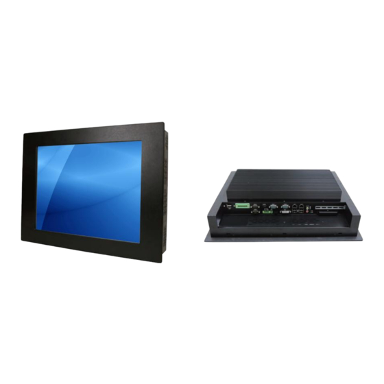
1.3 Brief Description of PC 8717 The PC8717 is the fanless and high performance panel -mount industrial panel PC with 17” TFT LCD. It powered by QM67 chipset and support Core i3-2310M 2.1GHz Processor. The panel PC has a rich variety of functions and peripherals. It comes with 2 x 2.5-inch hard disk drive and 1 x CF... -
Page 10: Chapter 2 Hardware Installation
Chapter 2 Hardware Installation 2.1 Mainboard Specifications Introduction Figure 2.1: Mainboard Overview... - Page 11 Figure 2.2: Mainboard Dimensions IPC -M8671 is a Mini-ITX industrial motherboard developed on the basis of Intel QM67,which provides abundant peripheral interfaces to meet the needs of different customers. Also, it features dual GbE ports, 6-COM ports and one Mini PCIE configuration. To satisfy the special needs of high-end customers, ADOtec designed 120Pin PCIe x16 and 40Pin PCIe x1 expansion interface.
- Page 12 Storage 4 x SATA Connector 1 x CFAST Slot (option) 2 x PCIe Gbe LAN by Intel 82574L Ethernet 4 x USB 2.0 stack ports for external 3 x USB 2.0 box Pin header for MIO1 4 x USB 2.0 box Pin header for MIO2 1 x USB 2.0 internal for mini PCIe 1 x RS232/422/485 port, DB9 connector for external (COM1) pin 9 w/5V/12V/Ring select...
-
Page 13: Jumpers Setting And Connectors
HDD LED status by MIO2 2 x COM Ports (COM1/COM2) External I/O 4 x USB 2.0 Ports (stack) port 2 x RJ45 GbE LAN Ports 1 x DVI-I Port 1 x HDMI Port 1 x Audio Ports (Mic, Line out) Watchdog Software programmable 1 –... - Page 14 Jumpers and Connectors Location- Bottom Figure 2.4: 1. RTC1/SRTC1: (2.0mm Pitch 1X2 Pin Header)CMOS clear jumper, CMOS clear operation will permanently reset old BIOS settings to factory defaults. RTC1/SRTC1 CMOS Open or NORMAL (Default) (RTC1Pin1-SRTC1 Pin close) Close 1-2 Clear CMOS Procedures of CMOS clear: a) Turn off the system and unplug the power cord from the power outlet.
- Page 15 Pin# Signal Name Pin1 VBAT Pin2 Ground 3. PS_SEL: (2.0mm Pitch 1X3 Pin Header),ATX Power and AT Power jumper setting. PS_SEL Mode Close 1-2 ATX Power (Default) Close 2-3 AT Power 4. PS_ON: (2.0mm Pitch 1X3 Pin Header),ATX Power and Auto Power on jumper setting. PS_ON Mode Close 1-2...
- Page 16 Pin# Power input Pin1 Ground Pin2 Ground Pin3 DC+12V Pin4 DC+12V 7. ATX (ATX Power option): (2.0mm Pitch 1X3 box Pin Header), connect PSON and 5VSB and Ground signal,support ATX Power model. Reserved. Pin# Signal Name Pin1 ATX PSON Pin2 ATX Ground Pin3 ATX 5VSB...
- Page 17 Ground Rotation detection Note: Output power of cooling fan must be limited under 5W. 11. A-DDR3/B-DDR3: (SO-DIMM 204Pin socket), DDRIII memory socket, the socket is located at the Top of the board and supports 204Pin 1.5V DDRIII 1066/1333MHz FSB SO-DIMM memory module up to 16GB. 12.
- Page 18 14. LVDS1: (1.25mm Pitch 2x20 Connector), For 18/24-bit LVDS output connector, Fully supported by Intel QM67 chipset, the interface features dual channel 18/24-bit output. Signal Name Pin# Pin# Signal Name VDD5 VDD5 Ground Ground VDD33 VDD33 LB_D0_N LA_D0_N LB_D0_P LA_D0_P Ground Ground LB_D1_N...
- Page 19 19. BT1: POWER on/off Button, They are used to connect power switch button. The two pins are disconnected under normal condition. You may short them temporarily to realize system startup & shutdown or awaken the system from sleep state. 20. JP1: (2.0mm Pitch 2x3 Pin Header),COM1 jumper setting, pin 1~6 are used to select signal out of pin 9 of COM1 port.
- Page 20 RS232 (Default): Pin# Signal Name DCD# (Data Carrier Detect) RXD (Received Data) TXD (Transmit Data) DTR (Data Terminal Ready) Ground DSR (Data Set Ready) RTS (Request To Send) CTS (Clear To Send) JP1 select Setting (RI/5V/12V) RS422 (option): Pin# Signal Name 422_R- 422_R+ 422_T-...
- Page 21 JP1 Pin# Function Close 1-2 COM2 RI (Ring Indicator) (default) Close 3-4 COM2 Pin9=+5V (option) Close 5-6 COM2 Pin9=+12V (option) 24. COM2: (Type DB9), Rear serial port, standard DB9 Male serial port is provided to make a direct connection to serial devices. Pin# Signal Name DCD# (Data Carrier Detect)
- Page 22 Close 1-2 COM6 RI (Ring Indicator) (default) Close 3-4 COM6 Pin9=+5V (option) Close 5-6 COM6 Pin9=+12V (option) 27. COM6 (2.0mm Pitch 2x5 Pin Header), COM6 Port, standard RS232 ports are provided. They can be used directly via COM cable connection. COM6 port is controlled by pins No.1~3 of JP3,select output Signal 5V or 12v, For details, please refer to description of JP3.
- Page 23 29. JACK1 (Diameter 3.5mm Double stack Jack), HD Audio port, An onboard Realtek ALC662 codec is used to provide high quality audio I/O ports. Line Out can be connected to a headphone or amplifier, MIC is the port for microphone input audio. 30.
- Page 24 35. PCIE1X (option) (4x10 Pin),Riser Card expansion connector.Can expand support two PCIe Signal. ASB-M8671T:PCIE1X connector in the top. ASB-M8671B:PCIE1X connector in the Bottom. MODEL PC1E16X / PCIE1X ASB-M8671T ASB-M8671B Bottom 36. M-PCIE1 (Socket 52Pin),mini PCIe socket, it is located at the top, it supports mini PCIe devices with USB2.0, SMBUS and PCIe signal.
- Page 25 Ground Ground Ground Ground Power 3P3V_S0 5V_USB_1011 USB11_N PWR_LED- USB11 Power MIO_PSON USB11_P Button Ground Ground 40. MIO2: (DF13-40P Connector),Front panel connector. Function Signal Name Pin# Pin# Signal Name Function P_LED+ PWR-LED HDD_LED H_LED+ P_LED- Ground USB01_OC- PSON+ MIO_PSON- USB23_OC- PSON- Ground RESET...
- Page 26 Pin7- Ground: RESET Button, They are used to connect reset button. The two pins are disconnected under normal condition. You may short them temporarily to realize system reset. Pin6- Pin8: POWER on/off Button, They are used to connect power switch button. The two pins are disconnected under normal condition.
- Page 27 Pin# Signal Name +DC5V Ground Ground +DC12V Note: Output current of the connector must not be above 1A. 43. SATA1/SATA2/SATA3/SATA4: (SATA 7P), SATA Connectors, Four SATA connectors are provided,SATA1 and SATA2 transfer speed up to 6.0Gb/s, SATA3 and SATA4 transfer speed up to 3.0Gb/s,RAID controller supporting RAID 0/1/5/10.
- Page 28 TB-525E161 connect to ASB-M8671T PCIE_16X connector, PCIE_16X is located at the top,It provides one PCIE X16 slot.
-
Page 29: Bios Setup
Chapter 3 BIOS Setup 3.1 Operations after POST Screen After CMOS discharge or BIOS flashing operation, press [Delete] key to enter CMOS Setup. After optimizing and exiting CMOS Setup, the POST screen displayed for the first time is as follows and includes basic information on BIOS, CPU, memory, and storage devices. 3.2 BIOS SETUP UTILITY Press [Delete] key to enter BIOS Setup utility during POST, and then a main menu containing system summary information will appear. -
Page 30: System Overview
BIOS Information Choose the system BIOS Vendor American Megatrends Default language Core Version 4.6.4.0 Compliancy UEFI 2.1 Project Version M8671V01 X64 Build Date and Time 05/21/2012 16:15:28 System Language [English] →←: Select Screen ↑↓ : Select Item System Date [Sun 07/10/2012] System Time [00:00:08] Enter: Select... -
Page 31: Advanced Settings
→←: Select Screen ↑↓ : Select Item System Date [Sun 07/10/2012] System Time [00:00:08] Enter: Select +/- : Charge Opt. F1 : General Help F2: Access Level Administrator Previous Values F3:Optimized Defaults F4:Save and Exit ESC Exit Version 2.10.1208. Copyright (C) 2010 American Megatrends , Inc. System Time: Set the system time, the time format is: Hour :... - Page 32 ►USB Configuration →←: Select Screen ►W83627UHG Super IO Configuration ↑↓ : Select Item ► HW Monitor Enter: Select ►Sandybridge PPM Configuration +/- : Charge Opt. F1 : General Help F2: Previous Values F3:Optimized Defaults F4:Save and Exit ESC Exit Version 2.10.1208. Copyright (C) 2010 American Megatrends , Inc. 3.4.1 PCI Subsystem Settings PCI Bus Driver Versio V2.03.00 PCI ROM Priority:...
- Page 33 [Disabled] [Enabled] Extended Tag: [Disabled] [Enabled] No Snoop: [Enabled] [Disabled] Maximum Payload: [Auto] [128 Bytes] [256 Bytes] [512 Bytes] [1024 Bytes] [2048 Bytes] [4096 Bytes] Maximum Read Request: [Auto] [128 Bytes] [256 Bytes] [512 Bytes] [1024 Bytes] [2048 Bytes] [4096 Bytes] PCI Express Link Settings: ASPM Support: [Disabled]...
- Page 34 [Disabled] ACPI Sleep State: [S3 (Suspend to RAM)] [Suspend Disabled] [S3 (Suspend to RAM)] Lock Legacy Resources: [Disabled] [Enabled] 3.4.3 CPU Configuration Socket 0 CPU Information: Intel(R) Core(TM) i5-2430M CPU @2.40GHz CPU Signature 206a7 Microcode Patch Max CPU Speed 2400 MHz Min CPU Speed 800 Mhz Processor Cores...
- Page 35 [Disabled] Hardware Prefetcher [Enabled] [Disabled] Adjacent Cache Line Prefetch [Enabled] [Disabled] Intel Virtualization Technology [Enabled] [Disabled] 3.4.4 SATA Configuration SATA Controller(S): [Enabled] [Disabled] SATA Mode Selection: [IDE] [AHCI] [RAID] SATA Test Mode: [Disabled] [Enabled] Serial ATA Port 0 Empty Software Preserve Unknown Serial ATA Port 1 Empty...
- Page 36 Serial ATA Port 5 Empty Software Preserve Unknown 3.4.5 Thermal Configuration Platform Thermal Configuration 3.4.6 PCH-FW Configuration ME FW Version 0.0.0.0 ME Firmware Mode ME Firmware Type Full Sku Firmware ME Firmware SKU Unidentified ME Firmware Update Configuration ME FW Image Re-Flash [Disabled] [Enabled] 3.4.7 USB Configuration...
- Page 37 [30 sec] [40 sec] Device power-up delay [Auto] [Manual] 3.4.8 W83627UHG Super IO Configuration W83627UHG Super IO Configuration Super IO Chip Winbond W83627UHG COM1 Configuration COM2 Configuration COM3 Configuration COM4 Configuration COM5 Configuration COM6 Configuration 3.4.9 HW Monitor PC Health Status System temperature : +48 C CPU temperature...
-
Page 38: Chipset Settings
CPU C6 report [Enabled] [Disabled] CPU C7 report [Enabled] [Disabled] Long duration power limit Long duration maintained Short duration power limit TCC active offset 3.5 Chipset Settings Aptio Setup Utility – Copyright (C) 2010 American Megatrends, Inc. Main Advanced Chipset Boot Security Save &... - Page 39 VT-d Capability Unsupported CHAP Device (B0:D7:F0) [Enabled] [Disabled] Thermal Device (B0:D4:F0) [Disabled] [Enabled] Enable NB CRID [Disabled] [Enabled] ►Graphics Configuration IGFX VBIOS Version 2120 IGFX Frequency 650 MHz Graphics Turbo IMON Current Primary Display [Auto] [IGFX] [PEG] [PCI] Internal Graphics [Auto] [Disabled] [Enabled]...
- Page 40 [288MB] [320MB] [352MB] [384MB] [416MB] [448MB] [480MB] [512MB] Dvmt Total Gfx Mem [256MB] [128MB] [MAX] GFX Low Power Mode [Enabled] [Disabled] LCD Control: Primary IGFX Boot Display [VBIOS Default] [CRT] [DVI] [LVDS] HDMI] LCD Panel Type [1024 X 768 LVDS1] [640 X 480 LVDS ] [800 X 600...
- Page 41 SDVD-LFP Panel Type [VBIOS Default] [1024 x 768 SDVO-LFP ] [1080 x1024 SDVO-LFP ] [1400 x 1050 SDVO-LFP ] [1600 x 1200 SDVO-LFP ] Panel Scaling [Auto ] [Off ] [Force Scaling ] Backlight Control [PWM Inverted ] [PWM Normal ] [GMBus Inverted ] [GMBus Normal ] [Auto ]...
- Page 42 [SECAM_B] [SECAM_D] [SECAM_G] [SECAM_H] [SECAM_K] [HDTV_STD_SMPTE_240M_1080i59] [HDTV_STD_SMPTE_240M_1080i60] [HDTV_STD_SMPTE_295M_1080i50] [HDTV_STD_SMPTE_295M_1080p50] [HDTV_STD_SMPTE_296M_720p50] [HDTV_STD_SMPTE_296M_720p60] [HDTV_STD_CEAEIA_7702A_480p60 [HDTV_STD_CEAEIA_7702A_480i60] TV2 Standard [VBIOS Default] [NTSC_M] [NTSC_M_J] [NTSC_433] [PAL_B] [PAL_G] [PAL_D] [PAL_H] [PAL_I] [PAL_M] [PAL_N] [SECAM_L] [SECAM_B] [SECAM_D] [SECAM_G] [SECAM_H] [SECAM_K] [HDTV_STD_SMPTE_240M_1080i59] [HDTV_STD_SMPTE_240M_1080i60] [HDTV_STD_SMPTE_295M_1080i50] [HDTV_STD_SMPTE_295M_1080p50] [HDTV_STD_SMPTE_296M_720p50] [HDTV_STD_SMPTE_296M_720p60] [HDTV_STD_CEAEIA_7702A_480p60 [HDTV_STD_CEAEIA_7702A_480i60]...
- Page 43 ALS Support [Disabled] [Enabled] Active LFP [Int-LVDS] [No-LVDS] [SDVO LVDS] [eDP Port-A] [eDP Port-D] Panel Color Depth [18 Bit] [24 Bit] ►DMI Configuration ►NB PCIe Configuration PEG0 [Not Present] PEG0 – Gen X [Auto] [Gen1] [Gen2] PEG1 [Not Present] PEG1 – Gen X [Auto] [Gen1] [Gen2]...
- Page 44 [Auto] [ASPM LOs] [ASPM L1] [ASPM LOsL1] ASPM LOs [Root Port Only] [Endpoint Port Only] [Both Root and Endpoint Ports] De-emphasis Control [-3.5 dB] [-6 dB] ►Memory Configuration Memory RC Version 1.2.10 Memory Frequency 1333 Mhz Total Memory 2048 MB (DDR3) DIMM#0 2048 MB (DDR3) DIMM#1...
- Page 45 [Disabled] Max TOLUD [Dynamic] [1GB] [1.25GB] [1.5GB] [1.75GB] [2GB] [2.25GB] [2.5GB] [2.75GB] [3GB] [3.25GB] NMode Support [Auto] [1N Mode] [2N Mode] Memory Scrambler [Enabled] [Disabled] RMT Crosser Support Memory Scrambler [Disabled] [Enabled] MRC Fast Boot [Enabled] [Disabled] Force Cold Reset [Enabled] [Disabled] Scrambler Seed Generation off...
- Page 46 ►Memory Thermal Configuration Memory Thermal Management [Enabled] [Disabled] PECI Injecred Temperature [Disabled] [Enabled] EXTTS# via TS-on-Board [Disabled] [Enabled] EXTTS# via TS-on-DIMM [Disabled] [Enabled] Virtual Temperature Sensor (VTS) [Disabled] [Enabled] ►GT-Power Management Control GT Info GT2 (0X116) RC6 (Render Standby) [Enabled] [Disabled] GT overClocking Support [Disabled]...
-
Page 47: Boot Settings
3.6 Boot Settings Aptio Setup Utility – Copyright (C) 2010 American Megatrends, Inc. Main Advanced Chipset Boot Security Save & Exit Boot Configuration Number of seconds to Setup Prompt Timeout Wait for setup Bootup Numlock State [On] Activation key. 65535(0xFFFF)means Quiet Boot [Disabled] Indef inite waiting. -
Page 48: Security Settings
[Upon Request] [Always] Option ROM Messages [Force BIOS] [Keep Current] Interrupt 19 Capture [Disabled] [Enabled] Boot Override SATA PM: ST9320423AS …… Launch EFI Shell from filesystem device 3.7 Security Settings Aptio Setup Utility – Copyright (C) 2010 American Megatrends, Inc. Main Advanced Chipset... -
Page 49: Save & Exit Settings
3.7.2 User Password Type the password with up to 20 characters and then press Enter key. This will clear all previously typed CMOS passwords. You will be requested to confirm the password. Type the password again and press Enter key. You may press Esc key to abandon password entry operation. - Page 50 →←: Select Screen Restore Defaults ↑↓ : Select Item Save user Defaults Restore user Defaults Enter: Select +/- : Charge Opt. F1 : General Help F2: Boot Override SATA PM:*** … Previous Values Launch EFI Shell from filesystem device F3:Optimized Defaults F4:Save and Exit ESC Exit Version 2.10.1208.
- Page 51 [Yes] [No] Restore user Defaults Restore User Defaults Restore User Defaults? [Yes] [No] Launch EFI Shell from filesystem device WARNING Not Found [ok]...
-
Page 52: Chapter 4 Installation Of Drivers
Chapter 4 Installation of Drivers This chapter describes the installation procedures for software and drivers under the windows XP. The software and drivers are included with the motherboard. The contents include Intel QM67 Chipset Driver, Intel (R) VGA Chipset Driver, Intel (R) Network Adapter, Realtek ALC662 Audio Codec Driver, Microsoft .NET Framework 3.5 Service, Touch Panel Driver. -
Page 53: Intel Chipset Driver
4.1 Intel Chipset Driver To install the Intel chipset driver, please follow the steps below. Step 1. Access Industrial Panel PC. Select Intel QM67 Chipset Driver. Step 2. Click Next to setup program. - Page 54 Step 3. Read the license agreement. Click Yes to accept the terms of the license agreement. Step 4. Click Next to continue.
- Page 55 Step 5. Click Next. Step 6. Select Yes, I want to restart this computer now. Click Finish then remove any installation media from the drives.
-
Page 56: Intel (R) Vga Chipset Driver
4.2 Intel (R) VGA Chipset Driver To install the VGA drivers, follow the steps below to proceed with the installation. Step 1. Select Intel(R) VGA Chipset Driver. Step 2. Click Yes to continue. - Page 57 Step 3. Click Next to continue setup program. Step 4. Read the license agreement. Click Yes to accept the license agreement.
- Page 58 Step 5. Click Next. Step 6. Click Continue Anyway.
- Page 59 Step 7. Click Continue Anyway. Step 8. Click Next.
- Page 60 Step 9. Select Yes, I want to restart this computer now. Click Finish.
-
Page 61: Intel(R) Network Adapter Driver
4.3 Intel(R) Network Adapter Driver To install the Intel 82574L Network adapter Driver, please follow the steps below. Step 1. Select Intel(R) Network Adapter. Step 1. Wait for extracting the files then click Next to continue. Step 2. Click Next. - Page 62 Step 3. Read the license agreement. Select I accept the terms in the license agreement then click Next to continue. Step 4. Select Drivers, Intel(R) PROSet for Windows* Device Manager, Advanced Network...
- Page 63 Services. Click Next to continue. Step 5. Click Install to begin the installation. Step 6. Click Finish to compete the installation.
-
Page 65: Realtek Hd Audio Driver Installation
4.4 Realtek HD Audio Driver Installation To install the Realtek High Definition (HD) Audio driver, please follow the steps below. Step 1. Select Realtek ALC662 HD Audio Codec Driver from the list. Step 2. Wait for extracting the files then click Next to continue. - Page 66 Step 3. Click Next to continue the installation. Step 4. Select Yes, I want to restart my computer now. then click Finish.
-
Page 67: Microsoft .Net Framework 3.5 Service
4.5 Microsoft .NET Framework 3.5 Service To install the Realtek High Definition (HD) Audio driver, please follow the steps below. Step 1. Select Microsoft .NET Framework 3.5 Service. Step 2. Select I have read and ACCEPT the terms of the License Agreement. Click Install. Step 2. - Page 68 Step 3. Click Exit to complete the installation.
-
Page 69: Chapter 5 Touch Screen Installation
Chapter 5 Touch Screen Installation This chapter describes how to install drivers and other software that will allow your PenMount 6000 Controller Board to work with different operating systems. NOTE: PenMount USB drivers support up to 15 USB controllers. 5.1 Introduction to Touch Screen Controller Board PenMount 6300 USB control board is a touch screen control board designed for USB interface and specific for 4, 5, 8-wire touch screens. - Page 70 Step 1. Please make sure your PenMount 6000 device had plugged in advance. If your device uses RS232 interface, please plugged in before the machine is turned on. When the system first detects the controller board, a screen appears that shows “Unknown Device”. Do not use this hardware wizard. Press Cancel.
- Page 71 Step 4. Read the license Agreement. Click I agree to agree the license agreement. Step 5. Choose the folder in which to install PenMount Windows Universal Driver. Click Install to start the installation.
- Page 72 Step 6. Wait for installation. Then click Next to continue. Step 7. Click OK.
- Page 73 Step 8 Click Finish to compete installation.
- Page 74 5.2.2 Software Functions Upon rebooting, the computer automatically finds the new 6000 controller board. The touch screen is connected but not calibrated. Follow the procedures below to carry out calibration. 1. After installation, click the PenMount Monitor icon “PM” in the menu bar. 2.
- Page 75 Advanced Calibration Advanced Calibration uses 4, 9, 16 or 25 points to effectively calibrate touch panel linearity of aged touch screens. Click this button and touch the red squares in sequence with a stylus. To skip, press ESC’. Command Calibration Command call calibration function.
- Page 76 Step 2. Click Standard Calibration to start calibration procedure NOTE: The older the touch screen, the more Advanced Mode calibration points you need for an accurate calibration. Use a stylus during Advanced Calibration for greater accuracy. Please follow the step as below:...
- Page 77 Step 3. Come back to PenMount Control Panel and select Tools then Click Advanced Calibration. Step 4. Select Device to calibrate, then you can start to do “Advanced Calibration”. NOTE: Recommend to use a stylus during Advanced Calibration for greater accuracy.
- Page 78 Setting...
- Page 79 About This panel displays information about the PenMount controller and driver version.
- Page 80 Multiple Monitors Multiple Monitors supports two to six touchscreen displays for one system. PenMount drivers for Windows 2000, XP 32/64bit, and 2003 support Multiple Monitors. This function supports from two to six touchscreen displays for one system. Each monitor requires its own PenMount touchscreen control board, either installed inside the displayor in a central unit.
- Page 81 Step 2. When the mapping screen message appears, click OK.
- Page 82 Step 3. Touch each screen as it displays Please touch this monitor. Press ‘S’ to skip Following this sequence and touching each screen is called mapping the touch screens. Step 4. After the setting procedure is finished, maybe you need to calibrate for each panel and controller.
- Page 83 About You can see how many devices of PenMount controller that are plugged to your system PenMount Monitor Menu Icon The PenMount monitor icon (PM) appears in the menu bar of Windows 2000/XP system when you turn on PenMount Monitor in PenMount Utilities.
- Page 84 PenMount Monitor has the following function PenMount Rotating Functions The PenMount driver for Windows 2000/XP supports several display rotating software packages. Windows Me/2000/XP support display rotating software packages such as: • Portrait‟s Pivot Screen Rotation Software • ATI Display Driver Rotate Function •...
- Page 85 NOTE: The Rotate function is disabled if you use Monitor Mapping...
- Page 86 17 inch industrial Panel PC, Core i3-2310M 2.1GHz embedded system, up to 16 GB DDR3 memory, 4 COM ports, 4 USB ports, 5-wire resistive type touch screen, Black color. All rights reserved. Product description and product specifications are subject to change without notice. For latest product information, please visit Acnodes’ web site at www.acnodes.com 14628 Central Ave. Chino, CA91710 Tel: 909.597.7588 Fax: 909.597.1939...
- Page 87 S u p p o r t M i n i P C I e & P C I e x 1 6 S l o t Detailed Views Dimensions All rights reserved. Product description and product specifications are subject to change without notice. For latest product information, please visit Acnodes’ web site at www.acnodes.com 14628 Central Ave. Chino, CA91710 Tel: 909.597.7588 Fax: 909.597.1939...
Need help?
Do you have a question about the PC 8717 and is the answer not in the manual?
Questions and answers