Sign In
Upload
Download
Table of Contents
Contents
Add to my manuals
Delete from my manuals
Share
URL of this page:
HTML Link:
Bookmark this page
Add
Manual will be automatically added to "My Manuals"
Print this page
×
Bookmark added
×
Added to my manuals
Manuals
Brands
REXROTH Manuals
Engine
MKD025A-144
Manual
REXROTH MKD025A-144 Manual
Mkd series, synchronous motors
Hide thumbs
1
2
3
4
Table Of Contents
5
6
7
8
9
10
11
12
13
14
15
16
17
18
19
20
21
22
23
24
25
26
27
28
29
30
31
32
33
34
35
36
37
38
39
40
41
42
43
44
45
46
47
48
49
50
51
52
53
54
55
56
57
58
59
60
61
62
63
64
65
66
67
68
69
70
71
72
73
74
75
76
77
78
79
80
81
82
83
84
85
86
87
88
89
90
91
92
93
94
95
96
97
98
99
100
101
102
103
104
105
106
107
108
109
110
111
112
113
114
115
116
117
118
119
120
121
122
123
124
125
126
127
128
129
130
131
132
133
134
135
136
137
138
139
140
141
142
143
144
145
146
147
148
149
150
151
152
153
154
155
156
157
158
159
160
161
162
163
164
165
166
167
168
169
170
171
172
173
174
175
176
177
178
179
180
181
182
183
184
page
of
184
Go
/
184
Contents
Table of Contents
Bookmarks
Table of Contents
Table of Contents
1 Introduction
Product Presentation
About this Documentation
2 Important Instructions on Use
Intended Use
Introduction
Fields of Use and Application
Non-Intended Use
3 Safety Instructions for Electric Drives and Controls
Introduction
Explanations
Hazards by Improper Use
General Information
Protection against Contact with Electrical Parts
Protection against Electric Shock by Protective Low Voltage (PELV)
Protection against Dangerous Movements
Protection against Magnetic and Electromagnetic Fields During Operation and Mounting
Protection against Contact with Hot Parts
Protection During Handling and Mounting
Battery Safety
Protection against Pressurized Systems
4 MKD Type Code
5 General Notes on Technical Data
60-K and 100-K Parameters
Operating Modes
Definition of Parameters
Sample Curve
6 Mkd025
Technical Data
Holding Brake
Type Code - Ordering Type
Speed - Torque - Caracteristics
Shaft Load
Dimensions
7 Mkd041
Technical Data
Holding Brake
Type Code - Ordering Name
Speed - Torque - Characteristics
Shaft Load
Dimensions
8 Mkd071
Technical Data
Holding Brake
Type Code - Ordering Name
Speed - Torque - Characteristics
Shaft Load
Dimensions
Blower Units
9 Mkd090
Technical Data
Holding Brake
Shaft Load
Dimensions
Blower Units
10 Mkd112
Technical Data
Holding Brake
Type Code - Ordering Name
Speed - Torque - Characteristics
Shaft Load
Dimensions
Blower Units
11 Accessories
Sealing Air Connection Accessories
Gearings
12 Connection System
Connection Diagram
Motors with Connector Box
Motors with Connector Receptacle
Connection Diagram
Blower Connector
Type (1)
Connecting and Mounting the Blower
Connection Cable
Dimensioning of Power Cable
Selection of Connection Cable
13 Application Instructions
Operating Conditions
Setup Height and Ambient Temperature
Vibration and Shock Loads
Degree of Protection
Option Sealing Air "Sealing Air: Principle" Connection
Selecting the Degree of Protection
Design and Installation Positions
Prime Coat and Housing Varnish
Blower
Holding Brakes
Output Shaft and Motor Bearing
Plain Shaft
Output Shaft with Key
Output Shaft with Shaft Sealing Ring
Bearings and Shaft Load
Motor Encoder
Acceptances, Approvals
CE Mark
UR, Cur Listing
14 Handling
Identifying the Goods
Type Labels
Instructions on the Packing
Storage
Transport and Handling
15 Assembly
Skilled Technical Personnel
Mounting the Motor
Connecting the Motor
Motor with Connection Box
Motors with Plug-In Connectors
Startup
Operation
16 Startup, Operation, and Maintenance
Maintenance
Cleaning
Bearings
Connection Cable
Holding Brake
Changing the Battery
17 Appendix
List of Standards
Selecting Power Cables
INS0680 1,0Mm²
INS0542 1,0Mm²
INS0480 1,5Mm²
INS0480 2,5Mm²
INS0480 4,0Mm²
INS0480 6,0Mm²
INS0480 10,0Mm²
INS0380 6,0Mm²
INS0380 10,0Mm²
INS0380 16,0Mm²
Selecting Encoder Cables
18 Index
19 Service & Support 19.1 Helpdesk
Service-Hotline
Internet
Vor der Kontaktaufnahme
Kundenbetreuungsstellen - Sales & Service Facilities
Advertisement
Quick Links
1
Product Presentation
2
Technical Data
Download this manual
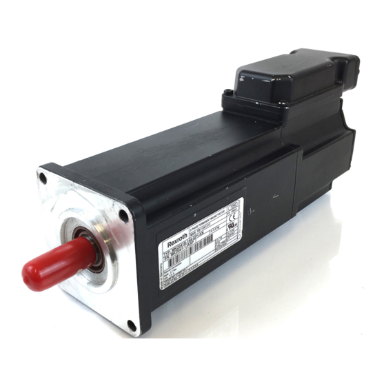
DATASHEET
INDRAMAT
MKD041B-144-GG0-KN
OTHER SYMBOLS:
RGB ELEKTRONIKA AGACIAK CIACIEK
SPÓŁKA JAWNA
Jana Dlugosza 2-6 Street
51-162 Wrocław
Poland
biuro@rgbelektronika.pl
+48 71 325 15 05
www.rgbautomatyka.pl
www.rgbelektronika.pl
www.rgbelektronika.pl
www.rgbautomatyka.pl
Table of
Contents
Previous
Page
Next
Page
1
2
3
4
5
Advertisement
Table of Contents
Need help?
Do you have a question about the MKD025A-144 and is the answer not in the manual?
Ask a question
Questions and answers
Related Manuals for REXROTH MKD025A-144
Engine REXROTH MAD100 Operating Instructions Manual
Indradyn a series. asynchronous motors mad / maf (71 pages)
Engine REXROTH MAD130 Operating Instructions Manual
Indradyn a series. asynchronous motors mad / maf (71 pages)
Engine REXROTH MKD041B-144 Manual
Mkd series, synchronous motors (184 pages)
Engine REXROTH MKD071B-061 Manual
Mkd series, synchronous motors (184 pages)
Engine REXROTH MKD025B-144 Manual
Mkd series, synchronous motors (184 pages)
Engine REXROTH MCR-C Manual
Radial piston motor for compact drives (16 pages)
Engine Rexroth MAD Series Project Planning Manual
Asynchronous motors mad/maf (220 pages)
Engine Rexroth IndraDyn A Series Project Planning Manual
Asynchronous motors mad/maf (220 pages)
Engine Rexroth MKE Series Project Planning Manual
Synchronous motors for potentially hazardous areas acc. to atex and ul/csa guidelines (162 pages)
Engine REXROTH MCL Operating Instructions Manual
Ironless linear motors (64 pages)
Engine REXROTH A2 Series Repair Instructions
Fixed displacement motor (28 pages)
Engine REXROTH A6VE Series 65 Instruction Manual
Variable plug-in (60 pages)
Engine REXROTH HyQuip 63 Series Instruction Manual
Variable plug-in motor (56 pages)
Engine REXROTH DOK-MOTOR*-ADF******** -IT01-EN-P Series Operating Instructions Manual
Asynchronous (68 pages)
Engine REXROTH GTE Series Project Planning Manual
Planetary gearboxes (86 pages)
This manual is also suitable for:
Mkd025b-058
Mkd041b-144
Mkd071b-024
Mkd071b-035
Mkd071b-061
Mkd090b-035
...
Show all
Mkd090b-046
Mkd090b-047
Mkd112a-024
Mkd090b-058
Mkd112a-058
Mkd112b-024
Mkd025b-144
Mkd041b-058
Mkd041b-143
Mkd112b-048
Mkd112b-058
Mkd112c-024
Mkd112c-058
Mkd112d-027
Table of Contents
Save PDF
Print
Rename the bookmark
Delete bookmark?
Delete from my manuals?
Login
Sign In
OR
Sign in with Facebook
Sign in with Google
Upload manual
Upload from disk
Upload from URL


Need help?
Do you have a question about the MKD025A-144 and is the answer not in the manual?
Questions and answers