Table of Contents
Advertisement
Quick Links
Advertisement
Table of Contents

Related Manuals for REXROTH MKE Series


Summary of Contents for REXROTH MKE Series
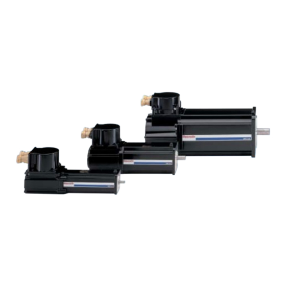
- Page 1 Industrial Electric Drives Linear Motion and Service Mobile Hydraulics and Controls Assembly Technologies Pneumatics Automation Hydraulics Rexroth MKE synchronous motors R911297663 for potentially hazardous areas Edition 03 acc. to ATEX and UL/CSA guidelines Project Planning Manual...
- Page 2 DOK-MOTOR*-MKE*GEN2***-PR03-EN-P 03/04 edition 2004 Bosch Rexroth AG Copyright Copying this document, giving it to others and the use or communication of the contents thereof without express authority, are forbidden. Offenders are liable for the payment of damages. All rights are reserved in the event of the grant of a patent or the registration of a utility model or design (DIN 34-1).
-
Page 3: Table Of Contents
Contents Contents Introduction to the Product MKE............................1-1 About this documentation ......................1-3 Important Instructions on Use Intended Use..........................2-1 Introduction .........................2-1 Fields of Use and Application ....................2-2 Non-Intended Use ........................2-2 Safety Instructions for Electric Drives and Controls Introduction ..........................3-1 Explanations ..........................3-1 Hazards by Improper Use......................3-2 General Information........................3-3 Protection Against Contact with Electrical Parts ................3-5 Protection Against Electric Shock by Protective Low Voltage (PELV) ........3-6... - Page 4 Contents Data sheet and characteristic curves .................4-18 Shaft loads ........................4-22 Dimensional Details Size 037...........................5-1 Size 047...........................5-4 Size 098...........................5-7 Size 118..........................5-10 Type Code Description ..........................6-1 Type code size 037 ........................6-6 Type code size 047 ........................6-7 Type code size 098 ........................6-8 Type code size 118 ........................6-9 Accessories and Options Motor encoder ..........................7-1 Holding Brakes.........................7-3...
- Page 5 Contents Output shaft with fitting key....................9-17 Output Shaft With Shaft Sealing Ring ................9-18 Bearings and Shaft Load ......................9-20 9.10 Holding Brakes........................9-24 Selecting Holding Brakes....................9-25 Sizing of Holding Brakes (Application) ................9-26 9.11 Acceptance and allowance .....................9-27 Motors in EU style ......................9-27 Motors in UL style......................9-28 10 Handling, Transport and Storage 10-1...
- Page 6 Contents 13.2 Selection of connection cable ....................13-3 Power cables........................13-4 Encoder cable ........................13-7 13.3 Declaration of conformity......................13-9 14 Service & Support 14-1 14.1 Helpdesk ..........................14-1 14.2 Service-Hotline........................14-1 14.3 Internet...........................14-1 14.4 Vor der Kontaktaufnahme... - Before contacting us..............14-1 14.5 Kundenbetreuungsstellen - Sales &...
-
Page 7: Introduction To The Product
The MKE-servo motors of the second generation fulfill the specifications according to ATEX and UL/CSA in one class. This permitts the worldwide use of Rexroth MKE-motors with one machine design only. In connection with the drive devices of Rexroth, the MKE-servomotors generates drive systems with high functionality for the use in hazardous areas. - Page 8 Introduction to the Product Design and components MKE motors are permanent-magnet motors with electronic commutation. Special magnet materials permit the motors to be designed with low inertia masses. The following figure shows the principal design of MKD motors. (1): Shaft (2): Stator with winding (3):...
-
Page 9: About This Documentation
Introduction to the Product About this documentation Structure of this Document Edition The present documentation contains safety regulations, technical data, and operating instructions for MKE motors. The individual chapters can be subdivided into the following focal points: Chapter Title Content Introduction to the Product General information Important Instructions on Use... - Page 10 Introduction to the Product Modifications as Compared with the Predecessor Version The following list shows the modifications as compared with the predecessor version DOK-MOTOR*-MKE*GEN2***-PR02 -EN-P Where? What? Chapter 3.9 Safety note “Protection against contact with hot parts” appendix. Chapter 4.4 New: Technical data and characteristic curve MKE098B-058 Chapter 4.5 New: Technical data and characteristic curve MKE118D-035...
- Page 11 This documentation refers to German, European and international technical standards. Documents and sheets on standards are subject to copyright protection and may not be passed on to third parties by Rexroth. If necessary, please address the authorized sales outlets or, in Germany, directly to: BEUTH Verlag GmbH...
- Page 12 Introduction to the Product DOK-MOTOR*-MKE*GEN2***-PR03-EN-P...
-
Page 13: Important Instructions On Use
Important Instructions on Use Intended Use Introduction In their design and manufacture, the products by Bosch Rexroth reflect the latest state of technology. Before they are delivered, they are checked for their operationally safe state. The products may only be used as intended. If they are not used as intended, situations may arise resulting in injuries to property and persons. -
Page 14: Fields Of Use And Application
Important Instructions on Use Fields of Use and Application AC servo motors of the MKE series by Bosch Rexroth are intended to be used as servo and main drive motors. The following are typical fields of application: • Machine tools •... -
Page 15: Safety Instructions For Electric Drives And Controls
If you do not have the user documentation for your equipment, contact your local Bosch Rexroth representative to send this documentation immediately to the person or persons responsible for the safe operation of this equipment. -
Page 16: Hazards By Improper Use
Safety Instructions for Electric Drives and Controls Hazards by Improper Use High voltage and high discharge current! Danger to life or severe bodily harm by electric shock! DANGER Dangerous movements! Danger to life, severe bodily harm or material damage by unintentional motor movements! DANGER High electrical voltage due to wrong... -
Page 17: General Information
Safety Instructions for Electric Drives and Controls General Information • Bosch Rexroth AG is not liable for damages resulting from failure to observe the warnings provided in this documentation. • Read the operating, maintenance and safety instructions in your language before starting up the machine. If you find that you cannot completely understand the documentation for your product, please ask your supplier to clarify. - Page 18 Safety Instructions for Electric Drives and Controls • Operation is only permitted if the national EMC regulations for the application are met. The instructions for installation in accordance with EMC requirements can be found in the documentation "EMC in Drive and Control Systems".
-
Page 19: Protection Against Contact With Electrical Parts
Safety Instructions for Electric Drives and Controls Protection Against Contact with Electrical Parts Note: This section refers to equipment and drive components with voltages above 50 Volts. Touching live parts with voltages of 50 Volts and more with bare hands or conductive tools or touching ungrounded housings can be dangerous and cause electric shock. -
Page 20: Protection Against Electric Shock By Protective Low Voltage (Pelv)
Protection Against Electric Shock by Protective Low Voltage (PELV) All connections and terminals with voltages between 0 and 50 Volts on Rexroth products are protective low voltages designed in accordance with international standards on electrical safety. High electrical voltage due to wrong... -
Page 21: Protection Against Dangerous Movements
Safety Instructions for Electric Drives and Controls Protection Against Dangerous Movements Dangerous movements can be caused by faulty control of the connected motors. Some common examples are: • improper or wrong wiring of cable connections • incorrect operation of the equipment components •... - Page 22 Safety Instructions for Electric Drives and Controls Dangerous movements! Danger to life, risk of injury, severe bodily harm or material damage! ⇒ Ensure personal safety by means of qualified and tested higher-level monitoring devices or measures DANGER integrated in the installation. Unintended machine motion is possible if monitoring devices are disabled, bypassed or not activated.
-
Page 23: Protection Against Magnetic And Electromagnetic Fields During Operation And Mounting
Safety Instructions for Electric Drives and Controls ⇒ Disconnect electrical power to the equipment using a master switch and secure the switch against reconnection for: - maintenance and repair work - cleaning of equipment - long periods of discontinued equipment use ⇒... -
Page 24: Protection Against Contact With Hot Parts
3-10 Safety Instructions for Electric Drives and Controls Protection Against Contact with Hot Parts Housing surfaces could be extremely hot! Danger of injury! Danger of burns! ⇒ Do not touch housing surfaces near sources of heat! Danger of burns! CAUTION ⇒... -
Page 25: Protection During Handling And Mounting
3-11 Safety Instructions for Electric Drives and Controls 3.10 Protection During Handling and Mounting Under certain conditions, incorrect handling and mounting of parts and components may cause injuries. Risk of injury by incorrect handling! Bodily harm caused by crushing, shearing, cutting and mechanical shock! ⇒... -
Page 26: Battery Safety
3-12 Safety Instructions for Electric Drives and Controls 3.11 Battery Safety Batteries contain reactive chemicals in a solid housing. Inappropriate handling may result in injuries or material damage. Risk of injury by incorrect handling! ⇒ Do not attempt to reactivate discharged batteries by heating or other methods (danger of explosion and cauterization). -
Page 27: Protection Against Pressurized Systems
3-13 Safety Instructions for Electric Drives and Controls 3.12 Protection Against Pressurized Systems Certain motors and drive controllers, corresponding to the information in the respective Project Planning Manual, must be provided with pressurized media, such as compressed air, hydraulic oil, cooling fluid and cooling lubricant supplied by external systems. - Page 28 3-14 Safety Instructions for Electric Drives and Controls Notes DOK-MOTOR*-MKE*GEN2***-PR03-EN-P...
-
Page 29: Technical Data
Technical data Technical data Description The speed-torque curves and the technical data are specified for different motor overtemperatures. Note: When selecting the technical data, observe the temperatures specified! Assembling and Measuring of The motor data and characteristic curves are determined using MKE the characteristic curve motors under the following conditions: •... -
Page 30: Operating Modes
Technical data Operating Modes Rexroth Indramat motors are documented according to the test criteria and measuring methods of EN 60034-1. The characteristic curves specified correspond to the operating modes S1 or S6. Load Electric losses Θ: Temperature Θ Highest temperature (motor housing) -
Page 31: Definition Of Parameters
Technical data Definition of Parameters Electric parameters Characteristic motor speed n With a DC link voltage of 540 V and at the characteristic speed, the continuous torque that can be output is approx. ½ continuous torque at standstill. Continuous torque at standstill The continuous torque that can be output at the motor output shaft at a speed of n = 0. - Page 32 Technical data (1): Course of the motor housing temperature over time Θ Highest temperature (motor housing) Thermal time constant Fig. 4-3: Thermal time constant Sample Curve M[Nm] n[min Thermal limit curves S1 continuous operation curve of the motor (according to EN 60034- 1;...
- Page 33 Technical data Notes DOK-MOTOR*-MKE*GEN2***-PR03-EN-P...
-
Page 34: Technical Data Mke037
Technical data Technical Data MKE037 Technical data sheet and characteristic curves Symbol Unit MKE037B Winding Characteristic speed 9000 Continuous torque at standstill 0.9 (0.8) Continuous current at standstill 4.7 (4.2) Max. torque (theoretical) Max. voltage 21.2 Constant torque at 20°C Nm/A 0.21 Constant voltage at 20°C... - Page 35 Technical data MKE037B-144 M [Nm] n [min-1] [1]: IndraDrive, controlled feed 3 x AC 400V [2]: IndraDrive, uncontrolled feed 3 x AC 480V [3]: IndraDrive, uncontrolled feed 3 x AC 440V [4]: IndraDrive, uncontrolled feed 3 x AC 400V S1 continuous operation characteristic curve; Natural conv. S6 intermitted operation characteristic curve (25% ED) max.
-
Page 36: Shaft Loads
Technical data Shaft loads Additional information about permissible radial and axial forces see chapter “Application notes”. Radial force F Diagram for determinating the maximum permissible radial force F radial radial. MKE037 Shaft plain Shaft with keyway x/mm Fig. 4-7: MKE037: permissible radial force (shaft and bearing load) Axial force F Determinate the maximum permissible axial force with the radial force axial... - Page 37 Technical data Notes DOK-MOTOR*-MKE*GEN2***-PR03-EN-P...
-
Page 38: Technical Data Mke047
4-10 Technical data Technical Data MKE047 Technical data sheet and characteristic curves Symbol Unit MKE047B Winding Characteristic speed 6000 Continuous torque at standstill Continuous current at standstill Max. torque (theoretical) 11.3 Max. voltage 32.0 Constant torque at 20°C Nm/A 0.42 Constant voltage at 20°C V/1000min 36.3... - Page 39 4-11 Technical data MKE047B-144 M [Nm] n [min-1] [1]: IndraDrive, controlled feed 3 x AC 400V [2]: IndraDrive, uncontrolled feed 3 x AC 480V [3]: IndraDrive, uncontrolled feed 3 x AC 440V [4]: IndraDrive, uncontrolled feed 3 x AC 400V S1 continuous operation characteristic curve;...
-
Page 40: Shaft Loads
4-12 Technical data Shaft loads Additional information about permissible radial and axial forces see chapter “Application notes”. Radial force F Diagram for determinating the maximum permissible radial force F radial radial. MKE047 Shaft plain Shaft with keyway n=500 min -1 n=1000 min -1 n=2000 min -1 n=3000 min -1... - Page 41 4-13 Technical data Notes DOK-MOTOR*-MKE*GEN2***-PR03-EN-P...
-
Page 42: Technical Data Mke098
4-14 Technical data Technical Data MKE098 Data sheet and characteristic curves Symbol Unit MKE098B Winding Characteristic speed 3200 4000 Continuous torque at standstill 12.0 12.0 Continuous current at standstill 13.9 17.5 Max. torque (theoretical) 43.5 43.5 Max. voltage 62.6 79.0 Constant torque at 20°C Nm/A 0.77... - Page 43 4-15 Technical data MKE098B-047 M [Nm] n [min-1] MKE098B-058 M [Nm] n [min-1] ]: M Natural conv. (S1 continuous operation) natural ]: M (S6 intermittent operation, 25% ED) 25%ED [1]: IndraDrive, controlled feed 3 x AC 400V [2]: IndraDrive, uncontrolled feed 3 x AC 480V [3]: IndraDrive, uncontrolled feed 3 x AC 440V [4]: IndraDrive, uncontrolled feed 3 x AC 400V Fig.
-
Page 44: Shaft Loads
4-16 Technical data Shaft loads Additional information about permissible radial and axial forces see chapter “Application notes”. Radial force F Diagram for determinating the maximum permissible radial force F radial radial. MKE098B Shaft plain 1800 Shaft with keyway 1600 1400 n=500 min -1 1200 n=1000 min -1... - Page 45 4-17 Technical data Notes DOK-MOTOR*-MKE*GEN2***-PR03-EN-P...
-
Page 46: Technical Data Mke118
4-18 Technical data Technical Data MKE118 Data sheet and characteristic curves Symbol Unit MKE118B Winding Characteristic speed 2000 4000 Continuous torque at standstill 28.0 28.0 Continuous current at standstill 21.7 40.1 Max. torque (theoretical) 102.0 102.0 Max. voltage 97.7 180.5 Constant torque at 20°C Nm/A 1.50... - Page 47 4-19 Technical data MKE118B-024 M [Nm] n [min-1] MKE118B-058 M [Nm] n [min-1] ]: M Natural conv. (S1 continuous operation) natural ]: M (S6 intermittent operation, 25% ED) 25%ED [1]: IndraDrive, controlled feed 3 x AC 400V [2]: IndraDrive, uncontrolled feed 3 x AC 480V [3]: IndraDrive, uncontrolled feed 3 x AC 440V [4]: IndraDrive, uncontrolled feed 3 x AC 400V Abb.
- Page 48 4-20 Technical data Symbol Unit MKE118D Winding Characteristic speed 2000 3000 Continuous torque at standstill 48.0 48.0 Continuous current at standstill 31.3 42.2 Max. torque (theoretical) 187.0 187.0 Max. voltage 140.9 190.0 Constant torque at 20°C Nm/A 1.78 1.32 Constant voltage at 20°C V/1000min 154.5 114.5...
- Page 49 4-21 Technical data MKE118D-027 M [Nm] n [min-1] MKE118D-035 (60K) M [Nm] S6 (25% ED) S1 (60K) n [min-1] ]: M Natural conv. (S1 continuous operation) natural ]: M (S6 intermittent operation, 25% ED) 25%ED [1]: IndraDrive, controlled feed 3 x AC 400V [2]: IndraDrive, uncontrolled feed 3 x AC 480V [3]: IndraDrive, uncontrolled feed 3 x AC 440V [4]: IndraDrive, uncontrolled feed 3 x AC 400V...
-
Page 50: Shaft Loads
4-22 Technical data Shaft loads Additional information about permissible radial and axial forces see chapter “Application notes”. Radial force F Diagram for determinating the maximum permissible radial force F radial radial. MKE118 Shaft plain Shaft with keyway x/mm Fig. 4-19: MKE118: permissible radial force (shaft and bearing load) Axial force F Determinate the maximum permissible axial force with the radial force... -
Page 51: Dimensional Details
Dimensional Details Dimensional Details Size 037 Fig. 5-1: Dimensions MKE037 ATEX DOK-MOTOR*-MKE*GEN2***-PR03-EN-P... - Page 52 Dimensional Details Fig. 5-2: Dimensions MKE037 UL/CSA DOK-MOTOR*-MKE*GEN2***-PR03-EN-P...
- Page 53 Dimensional Details Shaft end Fig. 5-3: Stub shaft MKE037 • Shaft end cylindrical according to DIN 748, Part 3, ed. 07.75. IEC 60072 (1971). • DS M3 centering hole according to DIN 332, Part 2, ed. 05.83, max. tightening torque for screw 0.7 Nm. •...
-
Page 54: Size 047
Dimensional Details Size 047 Fig. 5-5: Dimensions MKE047 ATEX DOK-MOTOR*-MKE*GEN2***-PR03-EN-P... - Page 55 Dimensional Details Fig. 5-6: Dimensions MKE047 UL/CSA DOK-MOTOR*-MKE*GEN2***-PR03-EN-P...
- Page 56 Dimensional Details Shaft end Fig. 5-7: Stub shaft MKE047 • Shaft end cylindrical according to DIN 748, Part 3, ed. 07.75. IEC 60072 (1971). • DS M5 centering hole according to DIN 332, Part 2, ed. 05.83, max. tightening torque for screw 3.0 Nm. •...
- Page 57 Dimensional Details Size 098 Fig. 5-9: Dimensions MKE098 ATEX DOK-MOTOR*-MKE*GEN2***-PR03-EN-P...
- Page 58 Dimensional Details Fig. 5-10: Dimensions MKE098 UL/CSA DOK-MOTOR*-MKE*GEN2***-PR03-EN-P...
- Page 59 Dimensional Details Shaft end Fig. 5-11: Stub shaft MKE098 • Shaft end cylindrical according to DIN 748, Part 3, ed. 07.75. IEC 60072 (1971). • DS M8 centering hole according to DIN 332, Part 2, ed. 05.83, max. tightening torque for screw 12.0 Nm. •...
- Page 60 5-10 Dimensional Details Size 118 Fig. 5-13: Dimensions MKE118 ATEX DOK-MOTOR*-MKE*GEN2***-PR03-EN-P...
- Page 61 5-11 Dimensional Details MM000043v01_NN.tif Abb. 5-1: Dimensions MKE118 UL/CSA DOK-MOTOR*-MKE*GEN2***-PR03-EN-P...
- Page 62 5-12 Dimensional Details Shaft end Fig. 5-11: Stub shaft MKE118 • Shaft end cylindrical according to DIN 748, Part 3, ed. 07.75. IEC 60072 (1971). • DS M10 centering hole according to DIN 332, Part 2, ed. 05.83, max. tightening torque for screw 25 Nm. •...
-
Page 63: Type Code
Type Code Type Code Description Each order of a product by Rexroth must be based on the type code. All available motor versions are uniquely described by their type code. The following figure describes the individual characters of the type code (abbrev. - Page 64 Abbrev. column 9 10 11 In connection with the motor frame size and motor frame length, the winding codes define the electric motor output data for all Rexroth Indramat motors. The type code specifies all possible winding codes, which are available for a motor frame size / length.
- Page 65 Type Code Output shaft Abbrev. column 14 To connect the machine elements to be driven to the motor shafts, the following options are available for MKE motors. Option Design Detail Plain shaft With end-sided centering hole with “DS” thread according to DIN 332, Part 2, Shaft with keyway Edition 05.83 1) Keyway according to DIN 6885, Sheet 1, ed.
- Page 66 Type Code Output Direction of Power Connector Abbrev. column 17 The power resp. the encoder connection on the MKE motors has to be made over the terminal box generally. When mounting, the favourite cable outlet direction can be set by twisting of the terminal box. Supplied Condition MKE motors are available with a terminal box.
- Page 67 Type Code Remark Please refer to this item for additionally required information concerning the handling of the type code. This includes, e.g, descriptions on footnotes, notes on availability, or exclusion clauses. DOK-MOTOR*-MKE*GEN2***-PR03-EN-P...
-
Page 68: Type Code Size 037
Type Code Type code size 037 Abbrev. Column 1 2 3 4 6 7 8 9 1 2 3 4 6 7 8 9 1 2 3 4 6 7 8 9 1 2 3 4 6 7 8 9 Example: M K E 0 3 7 B - 1 4 4 - G G 0 - B E N N Product... -
Page 69: Type Code Size 047
Type Code Type code size 047 Abbrev. Column 1 2 3 4 6 7 8 9 1 2 3 4 6 7 8 9 1 2 3 4 6 7 8 9 1 2 3 4 6 7 8 9 Example: M K E 0 4 7 B - 1 4 4 - G G 0 - B E N N Product... -
Page 70: Type Code Size 098
Type Code Type code size 098 Abbrev. Column 1 2 3 4 6 7 8 9 1 2 3 4 6 7 8 9 1 2 3 4 6 7 8 9 1 2 3 4 6 7 8 9 Example: M K E 0 9 8 B - 0 4 7 - K P 1 - R U N N Product... -
Page 71: Type Code Size 118
Type Code Type code size 118 Abbrev. Column 1 2 3 4 6 7 8 9 1 2 3 4 6 7 8 9 1 2 3 4 6 7 8 9 1 2 3 4 6 7 8 9 Example: M K E 1 1 8 D - 0 3 5 - P G 3 - K U N Product... - Page 72 6-10 Type Code DOK-MOTOR*-MKE*GEN2***-PR03-EN-P...
-
Page 73: Accessories And Options
These data are read by the digital intelligent drive controllers by Bosch Rexroth. This ensures • quick and easy startup, • adjustment between the motor and the drive controller without the risk of damage to the motor. - Page 74 Accessories and Options Resolverfeedback (RSF) Provided for relative indirect position detection. Replaces separate incremental encoders at the motor. Note: Characteristics of the resolverfeedback: After a voltage failure or after the first POWER ON, the axis must first always be moved to its home position, before the processing can begin. ⇒...
-
Page 75: Holding Brakes
Accessories and Options Holding Brakes Use the brake in normal operation only at a standstill and when performing the drive-internal brake check. The holding brake is required for holding the axis when the machine is in a de-energized state. Please consider the important application notes when using the holding brakes in chapter “9.8 Operation instructions and application notes”. -
Page 76: Gearboxes
Note: Encoders have no check on Ex-protection. For MKE motors with assembled encoders Bosch Rexroth assumes no liability. The Ex-protection verification certificate refers exclusively to the MKE motors. All further mechanical add-on pieces are not considered and need an additional discharging of the machine manufacturer. -
Page 77: Connection System
Connection System Connection System Overview MKE motors can either be delivered in housing construction E (according to European Standard EN) or in housing construction U (according to American Standard UL). The different instructions of the responsible public authority require the subsequent shown connection variants. -
Page 78: Connection Temperature Control
• ECODRIVE • DIAX04 • IndraDrive at Rexroth when MKE motors are used in hazardous areas. The connection of the PTC-resistors for the motor temperature analysis comes from the particular connection diagram of the drive-devices. Note:... -
Page 79: Connection Cable
Motor cables must have a minimum temperature stability of 80°C (176°F) Fig. 8-3: Information sign temperature resistance connection cable The cables of Rexroth, stated in the selective lists comply with this requirements. Ready-made connection cables Ready-made connection cables in various length for motors according to European Standard can be ordered at Bosch Rexroth. -
Page 80: Motor Connection According To European Standard (En)
Connection System Motor connection according to European standard (EN) The connection of the MKE motors, according to European standard, consists of the following components: • a power connector, incl. connection for temperature sensor and holding brake, • Encoder connection • additionally outside connection for an equipotential bonding conductor (according to EN 50014: 1992) Power and encoder connection The power and the encoder cables have to be lead together with the... -
Page 81: Connection According To American Standard (Ul)
Connection System Connection according to American standard (UL) The connection of the MKE motors, according to American standard, consists of the following components: • a power connector, incl. connection for temperature sensor and holding brake, single-wire construction • Encoder connection, standard-cabel construction •... -
Page 82: Dimensioning Power Cable
Dimensioning power cable The specified and calculated cross sectional area of the cables in Bosch Rexroth documentation base on RMS current and the assumption for “rotating motors”. Base for this calculation are the specified stillstand- constant current in the technical data. They are specified as peak values. -
Page 83: Recommendation For Handling And Application, Cable Assembly In Drag Chains
Connection System Recommendation for handling and application, Cable assembly in drag chains The reachable operating time of cables depends on the mode of installation and environmental factors at the place of action. By the various operating conditions could the following recommendations only be a help to make a long and faultless operation of the cables possible. - Page 84 Connection System • It is not allowed to fasten or to bind the cables together within the chain. When equipping the drag chain is must be taken into account that the height must be equally allocated symmetrically. This means, heavy cables have to be laid exoteric and the lightweight cables introversive.
-
Page 85: Notes Regarding Application
Notes Regarding Application Notes Regarding Application Hazardous areas Designation and definition Apparatus designation according to ATEX Principle of protection Use of Degree of Designation apparatus in Standard protection zone Pressure- EN 50014 resistant EEx d 1 oder 2 IEC 60079-0 casing V DE0171 Part EN 50021... - Page 86 Note: The MKE-motors of Rexroth are equipment according to equipment group II, category 2 for use in hazardous areas. Equipment Group II Category 3...
- Page 87 Notes Regarding Application The following designations are used in the European Standard EN 50014: 1992. 1992 verwendet. Electrical apparatus All items as a whole or in part for the utilization of electrical energy. These include, among others, items for the generation, transmission, distribution, storage, measurement,...
- Page 88 Notes Regarding Application Connection facilities Clamps, screws or other parts, used for the electrical connection of conductors of external circuits. Execution An insulation device carrying one or more conductors through an internal or external wall of a housing. Ex component A part of electrical apparatus or a module (other than an Ex cable entry), marked with the symbol “U”, which is not intended to be used alone and requires additional certification when incorporated into electrical...
- Page 89 Notes Regarding Application Degree of protection, groups and temperature classes The electrical apparatus for hazardous areas are classified into: Degree of protection The electrical apparatus are constructed according to the degree of protection. The claims are stipulated in special standards. Degree of protection Description Standard...
-
Page 90: Application Conditions For Mke Motors
Group II Application conditions for MKE motors Connection condition The motors are only allowed to operate with the Rexroth Drives DIAX04, ECODRIVE, DURADRIVE and INDRADRIVE. Controllers of other manufacturers are not permitted. The plug-in terminals in the terminal box have to be bolt together securely. - Page 91 Notes Regarding Application Emergency cutout Stored energy in the intermediate circuit has to be degraded or isolated as soon as possible via pressing the emergency stop, that in the case of failure the risk of an effect into the danger zone is reduced. (ATEX- directive 94/9/EG, appendix II, Cap.
- Page 92 Notes Regarding Application Internal motor brake (if existing) Use the brake inside the motor in normal operation only in standstill and for performing the drive-internal brake check. Hereby only poor temperatures of T < 100 °C are coming up and there is no spark, as no critical grinding occurs.
-
Page 93: Type Test Of The Motors According To European Standard (En)
Note: We recommend to use MKE motors in connection with drive devices of Rexroth Indramat in hazardous areas. When mounting the drive-devices in hazardous areas, the following components must fulfill the Ex-protection requirements. - Page 94 9-10 Notes Regarding Application Use in zone 1 and 2 It is allowed to use MKE motors of Rexroth Indramat in hazardous areas of zone 1 and 2. The relating drive devices and connections of the connection cables (power and feedback connection) must lay outside of the hazardous area.
-
Page 95: Type Test Of The Motors According To American Standard (Ul)
Note: It is allowed to use the MKE motors of type 037, 047 and 098 only in connection with the drive devices of Bosch Rexroth AG within hazardous areas. When mounting the drive-devices in hazardous areas, the following components must fulfill the Ex-protection requirements. - Page 96 9-12 Notes Regarding Application Use in Class I The described MKE motors are UL listed and are allowed to be used in hazardous areas according to Class I, Groups C and D. The relating drive devices and connections of the connection cables (power and feedback connection) must lay outside of the hazardous area.
-
Page 97: Setup Height And Ambient Temperature
9-13 Notes Regarding Application Setup Height and Ambient Temperature Nominal data The performance data specified for the motors apply in the following conditions: Ambient Temperature of 0 ºC up to +40 ºC Setup Height 0 m up to 1000 m above MSL. Exceeding the nominal data If you intend to use motors above these ranges, you must take the Derating curves... -
Page 98: Protection Class
Fig. 9-10: Ranges of IP degrees of protection for the motors Compatibility All Rexroth controls and drives are developed and tested according to the state-of-the-art. However, as it is impossible to follow up the permanent new development of all material which may come into contact with our controllers and drives (e.g. -
Page 99: Design And Installation Positions
9-15 Notes Regarding Application Design and Installation Positions MKE motors are available in design B05. Please refer to the table below for the types of installation permissible according to EN 60034-7:1993. Permissible types of installation Motor design Description Sketch Setup Flange attached on IM B5 the drive side of the... -
Page 100: Vibration And Shock Loads
9-16 Notes Regarding Application Vibration and Shock Loads MKE motors can carry loads, such as are typically occurring in case of presses, punches, or press inlets, only if they are attached in a shock- absorbed shock-decoupled way. construction such attachments must be checked in isolated cases. According to IEC 721-3-3 ed. -
Page 101: Output Shaft And Shaft Sealing Ring
Modifications to the fitting springs may be made only by the user himself and on his own responsibility. Bosch Rexroth do not give any warranty for modified featherkeys or motor shafts. -
Page 102: Output Shaft With Shaft Sealing Ring
9-18 Notes Regarding Application Output Shaft With Shaft Sealing Ring MKE motors are designed with radial shaft sealing rings according to DIN 3760 – design A. Radial shaft sealing ring Fig. 9-15: MKE radial shaft sealing ring Wear Radial shaft sealing rings are rubbing seals. Hence, they are subject to wear and generate frictional heat. - Page 103 Note on construction Bosch Rexroth recommend that any direct contact of the output shaft and the radial shaft sealing ring with the processing medium (coolant, material corrosion), caused by the type of machine or system construction, should be avoided.
-
Page 104: Bearings And Shaft Load
9-20 Notes Regarding Application Bearings and Shaft Load During operation, both radial and axial forces act upon the motor shaft and the motor bearings. The construction of the machine, the selected motor type and the attachment of driving elements on the shaft side must be adjusted to one another to ensure that the load limits specified are not exceeded. - Page 105 9-21 Notes Regarding Application Mean speed The run-up and braking times can be ignored in the calculation if the time in which the drive is operated at a constant speed is significantly greater than the acceleration and braking time. In the exact calculation of the mean speed according to the following example, the run-up and braking times are taken into account.
- Page 106 Note: If redundant attachment cannot be avoided, it is absolutely necessary to consult with Bosch Rexroth. Couplings The machine construction and the drive elements used must be carefully adapted to the motor type so that the loading limits of the shaft and the bearing are not exceeded.
- Page 107 9-23 Notes Regarding Application Bearing lifetime The bearing lifetime is an important criterion for the availability of MKE motors. When the lifetime is considered, the "mechanical lifetime" of bearing components and material is differentiated from the "grease lifetime" of the bearing lubricant. If the MKE motors are operated within the limits specified for radial and axial loads, the nominal service life of the bearings is as follows: The mechanical service life of the bearings is as follows:...
-
Page 108: Holding Brakes
9-24 Notes Regarding Application 9.10 Holding Brakes Use the brake in normal operation only at a standstill and when performing the drive-internal brake check. The holding brake is required for holding the axle when the machine is in a de-energized state. Hazardous movements! Persons endangered by falling or descending axles! ⇒... -
Page 109: Selecting Holding Brakes
9-25 Notes Regarding Application Functional test Before start-up and during operation specifications the brake function must be tested with the ”brake command” function. By applying a small amount of motor torque, the brake is tested for slippage. Additional information and specifications of this function may be found in the ECODRIVE firmware functional descriptions. -
Page 110: Sizing Of Holding Brakes (Application)
9-26 Notes Regarding Application Sizing of Holding Brakes (Application) The physical conditions of holding brakes require consideration of two states. Beyond the normal operation also the incident must be viewed. The effective braking torques are physically different. Normal Operation In normal operation, using the holding brake for clamping of an axis standstill, the brake`s static torque (M4) rating in the data sheets applies directly as static friction (M4) –... -
Page 111: Acceptance And Allowance
9-27 Notes Regarding Application 9.11 Acceptance and allowance Motors in EU style Declaration of conformity Declarations of conformity certifying the structure of and the compliance with the applicable EN standards and EC guidelines are available for all MKE motors. If necessary, these declarations of conformity can be requested from the pertinent sales office. -
Page 112: Motors In Ul Style
9-28 Notes Regarding Application Motors in UL style UL, CSA Listing The MKE motors listed below have been presented to the UL authorities “Underwriters Laboratories Inc.®”. • MKE037B • MKE047B • MKE098B The motors have been approved by the UL authorities under the file number E203009 and have been marked on their motor type label with the following sign: Fig. -
Page 113: Handling, Transport And Storage
10-1 Handling, Transport and Storage Handling, Transport and Storage 10.1 Supplied Condition On delivery are the MKE motors packed in cardboard boxes or crates. Packing units on pallets are secured by retaining straps. Injuries due to uncontrolled movement of the retaining straps when cutting! ⇒... -
Page 114: Identification
10-2 Handling, Transport and Storage 10.2 Identification Shipping documents and delivery note The total scope of a delivery can be seen in the delivery note or waybill. However, the contents of a delivery can be distributed over several packages. Each individual package can be identified using the shipment label attached to the outside. -
Page 115: Transport And Storage
10-3 Handling, Transport and Storage 10.3 Transport and storage Damages or injuries and invalidation of the warranty due to improper handling! ⇒ Avoid mechanical stressing, throwing, tipping or dropping of the products. CAUTION ⇒ Use only suitable tackles. ⇒ Never lift the motor out of the optional blower housing. - Page 116 10-4 Handling, Transport and Storage Fig. 10-2: Lifting and transporting the motors by means of lifting sling belts Bearing Damage and loss of the warranty by incorrect storage! ⇒ Store the motors dry, vibration-free, dust-free and corrosion-protected in horizontal condition CAUTION ⇒...
-
Page 117: Installation
11-1 Installation Installation 11.1 Safety Injuries due to live parts! Lifting of heavy loads! ⇒ Install the motors only when they are not under power and not connected electrically. ⇒ Use suitable tackles, protective equipment and WARNING protective clothing during transport. ⇒... -
Page 118: Mechanical Mounting - Motor Assembly
11-2 Installation 11.3 Mechanical mounting – Motor assembly Mounting the flange MKE motors are produced for flange mounting (size B05) according to DIN 42950 part 1, Edition 08.77. Details for the fastening holes can be found in the corresponding dimension sheet. To fix the flange, we recommend to use the screws and tightening torques listed in the table below. -
Page 119: Assembly
After proper mechanical assembly, make the electrical connections. 11.4 Electrical connection – Motor connection It is recommended that you use ready-to-use Rexroth connection cables. These cables provide a number of advantages, such as UL/CSA approval, extreme load capability and resistance as well as a design suitable for EMC. -
Page 120: Motor Connection According To European Standard (En)
The MKE motors are provided with a terminal box. When connecting the motor, cables, which are according to the ready-made cables of Rexroth, have to be used. The cables have to be assembled as follows: 2 ... - Page 121 5. Remove the EExd-Cable screwing for the encoder cable. Note: When using the ready-made cables of Rexroth, the EExd cable screwing on the motor is not needed. 6. Insert the encoder cable (6) into the terminal box lid (9) (see Fig. 11- 7.
- Page 122 11-6 Installation Fig. 11-3: Plug-in interlock 15. Connect the encoder connector X2 on the motor connection plate. Mount the terminal box lid 16. Set the terminal box lid (9) on the motor. Make sure that no wire can be crushed or damaged. 17.
- Page 123 Installation MKE118 Cable fittings MKE118/EU motors of Rexroth are to be connected with especially to the cabel outer diameter matched Ex-threads. Consider the notes of the manufacturer: All cable entries of type LE... have to be included into the type check according to EN 50018, Section 15.1.3 (overpressure) the group...
- Page 124 11-8 Installation Danger of explosion, danger to life, heavy injury and property damage ⇒ Only according to the rules mounted cable fittings hinder the penetration of hazardous gases/dusts. DANGER ⇒ Make sure that only grommets are used, which are adjusted to the cable diameter. The following steps are necessary: 1.
- Page 125 11-9 Installation (1): Sealing (2): screwing (3): Use grommets according to the cable diameter. (4): Union nut (5): Ready-made power cable (6): Terminal box lid (7): Lid screws (8): Ready-made encoder cable Fig. 11-7: Mounting the EExd-fitting and cable MKE118 Note: Loosen and tighten the cable fittings is not permitted.
- Page 126 11-10 Installation Einführen Leistungs- und Feedbackkabel Feeding in power and feedback cables Absetz- bzw. Abisolierlängen Shealth- insulation stripping feedback cable power cable exterior mantel power Feedback connecting litz wires connecting litz wires feedback connector gn/ye Motoranschluß mit Steckerverriegelung für X3 Motor Connection with Plug in interlock X3 T1 T2 Br+ Br - Fig.
-
Page 127: Motor Connection According To American Standard (Ul)
Installation Motor connection according to American standard (UL) MKE037, -047, -098 The connection diagrams by Rexroth are exclusively intended for the preparation of system circuit diagrams! • Connect the motor as described in the circuit diagram of the machine manufacturer. As additional help, the relevant connecting diagram can be used (see chapter 11.2 “Connecting diagram”). - Page 128 11-12 Installation MKE118 The connection diagrams by Rexroth are exclusively intended for the preparation of system circuit diagrams! • Connect the motor as described in the circuit diagram of the machine manufacturer. As additional help, the relevant connecting diagram can be used (see chapter 11.2 “Conneting diagram”).
-
Page 129: Startup, Operation And Maintenance
⇒ It is not allowed to operate with damaged products! ⇒ Contact Rexroth for missing information or support during commissioning! The following commission notes refer to the MKE motors as part of a drive-system with drive and control devices. -
Page 130: Deactivation
7. Before dismantling, secure the motor against falling or movements before disconnecting the mechanical connections. 12.4 Maintenance Synchronous motors of the MKE series operate without wear within the given operating conditions. However, operation under unfavorable conditions can lead to limitations in availability. -
Page 131: Bearing
• the nominal bearing service life has been reached, • running noise can be heard. Note: We recommend that bearings are replaced by the Bosch Rexroth Service. Connection Cable Check connection lines for damage at regular intervals and replace them, if necessary. -
Page 132: Holding Brake
4 and 5 of the grinding-in process. If the specified holding torque is not attained after the second grinding-in process, the holding brake is not operable. Notify Rexroth Service. During operation If holding brakes are required only sporadically (braking cycle >48 h) during operation, film rust may develop on the brake friction surface. -
Page 133: Changing The Battery
12-5 Startup, Operation and Maintenance Changing the battery Drive control systems of Bosch Rexroth observe voltage of battery safely and give just in time a warning “change battery”. Danger of Explosion! Death, heavy personal injury and damage by opening the motor housing in hazardous areas! ⇒... - Page 134 12-6 Startup, Operation and Maintenance Assemble the battery 1. Connect the ready-made battery according to the motor type and fasten it with the clamping apparatus (4) and the screws (3) (tightening torque maximum 1,0 Nm). Note: Do not squeeze the battery cable! 2.
-
Page 135: Troubleshooting
12-7 Startup, Operation and Maintenance 12.5 Troubleshooting preparation 12.6 Dismantling Fatal injury due to errors in activating motors and moving elements! ⇒ Do not work on unsecured and operating machines. ⇒ Secure the machine against accidental movements DANGER and against unauthorized operation. ⇒... -
Page 136: Waste Disposal
The manufacturing process of the products is made in a way that is energy and raw material-optimated and permitts a recycling and a utilization of incidental waste. Bosch Rexroth is trying to replace polluted raw materials and supplies by environmentally alternatives regularly. Bosch Rexroth products do not contain any kind of dangerous substances which could be released at appropriate use. - Page 137 12-9 Startup, Operation and Maintenance Packing High-quality products need optimal packaging. The packaging material consists of paper, wood and polystyrene. They can be recycled everywhere. In view of ecological reasons, a return transport should not take place. DOK-MOTOR*-MKE*GEN2***-PR03-EN-P...
- Page 138 12-10 Startup, Operation and Maintenance DOK-MOTOR*-MKE*GEN2***-PR03-EN-P...
-
Page 139: Appendix
13-1 Appendix Appendix 13.1 List of standards Standard Edition Title Concordance Richtlinie 94/9//EG des Europäischen Parlaments und des Rates vom 23. März 1994 zur Angleichung der Rechtsvorschriften der 94/9/EG 1994-03-23 Mitgliedsstaaten für Geräte und Schutzsysteme zur bestimmungsgemäßen Verwendung in explosionsgefährdeten Bereichen ATEX-LEITLINIEN (Erste Ausgabe) Leitlinien zur Anwendung der Richtlinie 94/9//EG des Europäischen Parlaments und des Rates vom... - Page 140 13-2 Appendix DIN EN 50020; Electrical apparatus for potentially explosive atmospheres - Intrinsic 1996-04 VDE 0170/0171 EN 50020(1994-08) safety "i"; German version EN 50020:199 Part 7 DIN EN 50178; Electronic equipment for use in power installations; German version EN 1998-04 EN 50178(1997-10) 50178:1997 VDE 0160...
-
Page 141: Selection Of Connection Cable
13-3 Appendix 13.2 Selection of connection cable In the following see from the documentation “Connection cables, selection data” all selection graphics for all ready-made connection cables for MKE motors of generation 2 (design EN, type code position 18 = E). The wire diameters according to the particular continuous stand-still current for the power cables can be seen in the following table. -
Page 142: Power Cables
13-4 Appendix Power cables direct connection IKG0310/xxx,x IKG0311/xxx,x IKG0329/xxx,x IKG0312/xxx,x IKG0312/xxx,x IKG4145/xxx,x Attention: IKG0309/xxx,x max. length of cabel 25 m Danger of explosion! z.B: IKG0309/xxx,x IKG4006 IKG4008 IKG4009 IKG4017 Hazardous area! IKG4099 IKG4119 plug connection Fig. 13-3: Connection cross-section 1.0 mm² (MKE037, -047, -098) DOK-MOTOR*-MKE*GEN2***-PR03-EN-P... - Page 143 13-5 Appendix direct connection IKG0317/xxx,x IKG0313/xxx,x IKG0314/xxx,x IKG4146/xxx,x IKG4148/xxx,x Attention: IKG0324/xxx,x max. length of cabel 25 m Danger of explosion! z.B. IKG4116 IKG0318/xxx,x IKG4139 IKG4162 IKG4167 IKG4168 IKG4170 Hazardous area! plug connection Fig. 13-4: Connection cross-section 2.5 mm² (MKE118) DOK-MOTOR*-MKE*GEN2***-PR03-EN-P...
- Page 144 13-6 Appendix direct connection IKG0326/xxx,x IKG0322/xxx,x Attention: IKG0327/xxx,x max. length of cabel 25 m IKG4149/xxx,x Danger of explosion! Hazardous area! z.B. IKG4102 IKG0328/xxx,x IKG4107 IKG4110 IKG4118 plug connection Fig. 13-5: Connection cross-section 6.0 mm² (MKE118) DOK-MOTOR*-MKE*GEN2***-PR03-EN-P...
-
Page 145: Encoder Cable
13-7 Appendix Encoder cable für direkte Verbindungen Attention: max. length of cabel 25 m Danger of explosion! z.B. IKS4065 IKS4374 Hazardous area! plug connection Fig. 13-6: Encoder cable (MKE037, -047, -098) DOK-MOTOR*-MKE*GEN2***-PR03-EN-P... - Page 146 13-8 Appendix direct connection IKS0225/xxx,x IKS0226/xxx,x Attention: max. length of cabel 25 m Danger of explosion! z.B. IKS0227/xxx,x IKS4065 IKS4374 Hazardous area! IKS0228/xxx,x plug connection Fig. 13-7 Encoder cable (MKE118) DOK-MOTOR*-MKE*GEN2***-PR03-EN-P...
-
Page 147: Declaration Of Conformity
13-9 Appendix 13.3 Declaration of conformity A certificate of conformity is attached to every supplied motor. Additional copies can be ordered at your responsible selling agency. DOK-MOTOR*-MKE*GEN2***-PR03-EN-P... - Page 148 13-10 Appendix MX000006v01_D3.tif Fig. 13-8: Declaration of conformity (page 1) DOK-MOTOR*-MKE*GEN2***-PR03-EN-P...
- Page 149 13-11 Appendix MX000007v01_D3.tif Fig. 13-9: Declaration of conformity (page 2) DOK-MOTOR*-MKE*GEN2***-PR03-EN-P...
- Page 150 13-12 Appendix DOK-MOTOR*-MKE*GEN2***-PR03-EN-P...
-
Page 151: Service & Support
14-1 Service & Support Service & Support 14.1 Helpdesk Unser Kundendienst-Helpdesk im Hauptwerk Lohr Our service helpdesk at our headquarters in Lohr am am Main steht Ihnen mit Rat und Tat zur Seite. Main, Germany can assist you in all kinds of inquiries. Sie erreichen uns Contact us 49 (0) 9352 40 50 60... -
Page 152: Kundenbetreuungsstellen - Sales & Service Facilities
C A L L E N T R Y C E N T E R H O T L I N E ERSATZTEILE / SPARES Rexroth Indramat GmbH MO – FR MO – FR verlängerte Ansprechzeit Bgm.-Dr.-Nebel-Str. 2 / Postf. 1357... - Page 153 - Italien Netherlands – Niederlande/Holland Netherlands - Niederlande/Holland Bosch Rexroth S.p.A. Bosch Rexroth S.p.A. Bosch Rexroth B.V. Bosch Rexroth Services B.V. Via Mascia, 1 Viale Oriani, 38/A Kruisbroeksestraat 1 Technical Services 80053 Castellamare di Stabia NA 40137 Bologna (P.O. Box 32)
- Page 154 - Tschechien Czech Republic - Tschechien Hungary - Ungarn Poland – Polen DEL a.s. Bosch -Rexroth, spol.s.r.o. Bosch Rexroth Kft. Bosch Rexroth Sp.zo.o. Strojírenská 38 Hviezdoslavova 5 Angol utca 34 ul. Staszica 1 591 01 Zdar nad Sázavou 627 00 Brno 1149 Budapest 05-800 Pruszków...
- Page 155 Australia - Australien Australia - Australien China China AIMS - Australian Industrial Bosch Rexroth Pty. Ltd. Shanghai Bosch Rexroth Shanghai Bosch Rexroth Machinery Services Pty. Ltd. No. 7, Endeavour Way Hydraulics & Automation Ltd. Hydraulics & Automation Ltd. 28 Westside Drive...
- Page 156 Canada West - Kanada West Mexico Mexico Bosch Rexroth Canada Corporation Bosch Rexroth Canada Corporation Bosch Rexroth Mexico S.A. de C.V. Bosch Rexroth S.A. de C.V. Burlington Division 5345 Goring St. Calle Neptuno 72 Calle Argentina No 3913 3426 Mainway Drive Burnaby, British Columbia Unidad Ind.
-
Page 157: Index
15-1 Index Index Bearing Wear 9-23 Bearing failure 9-23 Brake torque 9-25 Characteristic continuous operation curve 4-4 Characteristic motor speed 4-3 Characteristic voltage limit curves 4-4 Connection Cable 12-3 Continuous current at standstill 4-3 Continuous torque at standstill 4-3 Cooling ribs 12-2 Cycle duration 4-2 Cyclic duration factor 4-2 Degree of protection 9-14... - Page 158 15-2 Index Mass 4-3 Maximum speed 4-3 Mean speed 9-21, 9-23 Moment of inertia of the rotor 4-3 Non-intended use 2-2 Consequences, disclaimer of liability 2-1 Number of pole pairs 4-3 ON time 4-2 Operating modes 4-2 Output shaft Plain shaft 6-3 Outside systems 1-5 Peak current 4-3 Processing cycle 9-21...
- Page 159 15-3 Index DOK-MOTOR*-MKE*GEN2***-PR03-EN-P...
- Page 160 15-4 Index DOK-MOTOR*-MKE*GEN2***-PR03-EN-P...
- Page 162 Bosch Rexroth AG Electric Drives and Controls P.O. Box 13 57 97803 Lohr, Germany Bgm.-Dr.-Nebel-Str. 2 97816 Lohr, Germany Phone +49 93 52-40-50 60 +49 93 52-40-49 4 1 service.svc@boschrexroth.de www.boschrexroth.com Printed in Germany R911297663 DOK-MOTOR*-MKE*GEN2***-PR03-EN-P...
Need help?
Do you have a question about the MKE Series and is the answer not in the manual?
Questions and answers