
Related Manuals for REXROTH A6VE Series 65


Summary of Contents for REXROTH A6VE Series 65
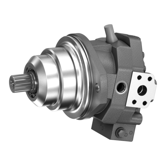
- Page 1 Variable plug-in motor A6VE Series 65 and 71 Instruction manual Replaces: 09.2013 RE 91616-01-B/10.2014 English...
- Page 2 © This document, as well as the data, specifications and other information set forth in it, are the exclusive property of Bosch Rexroth AG. It may not be reproduced or given to third parties without its consent. The cover shows an example application.
-
Page 3: Table Of Contents
7.4.5 Installation on a gearbox 7.4.6 Installation with cardan shaft 7.4.7 Completing installation 7.4.8 Hydraulically connecting the axial piston unit 7.4.9 Electrically connecting the axial piston unit Performing flushing cycle RE 91616-01-B/10.2014, A6VE Series 65 and 71, Bosch Rexroth AG... - Page 4 11.3 Carrying out removal 11.4 Preparing the components for storage or further use Disposal Extension and conversion Troubleshooting 14.1 How to proceed with troubleshooting 14.2 Malfunction table Technical data Alphabetical index Bosch Rexroth AG, A6VE Series 65 and 71, RE 91616-01-B/10.2014...
-
Page 5: About This Documentation
Axial piston units for operation with HF hydraulic fluids 90223 Data sheet Contains additional information on the use of Rexroth axial piston units with HF hydraulic fluids. Information for the use of hydrostatic drives at low temperatures 90300-03-B... -
Page 6: Display Of Information
Identifies a dangerous situation that may result in minor to CAUTIOn moderate injuries if it is not avoided. NOTICE Property damage: The product or the environment may be damaged. Bosch Rexroth AG, A6VE Series 65 and 71, RE 91616-01-B/10.2014... -
Page 7: Symbols
Rexroth document in the English language VDI 2230 Directive for the systematic calculation of high duty bolted joints and joints with one cylindrical bolt from the VDI (Verein Deutscher Ingenieure - Association of German Engineers) RE 91616-01-B/10.2014, A6VE Series 65 and 71, Bosch Rexroth AG... -
Page 8: Safety Instructions
Any use other than that described as intended use shall be considered as improper and is therefore impermissible. Bosch Rexroth AG shall accept no liability whatsoever for damages resulting from improper use. The user shall bear all risks arising from improper use. -
Page 9: Personnel Qualifications
• Only use genuine Rexroth accessories and spare parts to ensure there is no risk to personnel from unsuitable spare parts. • Adhere to the technical data and ambient conditions specified in the product documentation. -
Page 10: Product-Specific Safety Instructions
Operating the unit above the permissible maximum pressure can cause components to burst and hydraulic fluid to escape under high pressure. ▶ Changes to the factory settings must only be made by Bosch Rexroth specialist personnel. ▶ In addition, a pressure relief valve is needed as back-up in the hydraulic system. - Page 11 ▶ For safety reasons, axial piston variable motors with beginning of control at V g min (e.g., HA) are not permissible for winch drives (e.g. anchor winches). RE 91616-01-B/10.2014, A6VE Series 65 and 71, Bosch Rexroth AG...
- Page 12 Check whether remedial measures for your application are needed on your machine in order to put the driven consumer in a safe state (e.g. safe stop). ▶ If necessary, make sure that these are properly implemented. Bosch Rexroth AG, A6VE Series 65 and 71, RE 91616-01-B/10.2014...
-
Page 13: Personal Protective Equipment
The personal protective equipment is the responsibility of the user of the axial piston unit. Observe the safety regulations and provisions in your country. All components of the personal protective equipment must be intact. RE 91616-01-B/10.2014, A6VE Series 65 and 71, Bosch Rexroth AG... -
Page 14: General Instructions On Damage To Property And The Product
Before installation, remove all fluids from the axial piston unit to prevent mixing with the hydraulic fluid used in the machine/system. ▶ Any mixing of hydraulic fluids from different manufacturers or different types from the same manufacturer is not generally permitted. Bosch Rexroth AG, A6VE Series 65 and 71, RE 91616-01-B/10.2014... - Page 15 Use an oil binding agent if hydraulic fluid is spilt. ▶ Observe the information in the safety data sheet for the hydraulic fluid and the specifications provided by the system manufacturer. RE 91616-01-B/10.2014, A6VE Series 65 and 71, Bosch Rexroth AG...
- Page 16 The warranty only applies to the delivered configuration. The warranty entitlement is rendered void if the product is incorrectly installed, commissioned or operated, as well as in cases of improper use and/or handling. Bosch Rexroth AG, A6VE Series 65 and 71, RE 91616-01-B/10.2014...
-
Page 17: Scope Of Delivery
Included in the scope of delivery are: • Axial piston unit as per order confirmation The following parts are also fitted prior to delivery: • Protective covers (1) • Protective plug/threaded plug (2) RE 91616-01-B/10.2014, A6VE Series 65 and 71, Bosch Rexroth AG... -
Page 18: About This Product
5.2.1 layout of the axial piston unit Fig. 2: layout of the A6VE 1 Drive shaft 4 Port plate 6 Cylinder 2 Control piston 5 Lens plate 7 Piston 3 Stroke piston Bosch Rexroth AG, A6VE Series 65 and 71, RE 91616-01-B/10.2014... -
Page 19: Functional Description
Various control devices are available depending on requirements. Information about this can be found in data sheet 91615 and 91616. RE 91616-01-B/10.2014, A6VE Series 65 and 71, Bosch Rexroth AG... -
Page 20: Product Identification
4 Specified area for test stamp 11 Material number of the axial 5 Direction of rotation (looking at piston unit drive shaft) – here: bi-directional 12 Ordering code 6 Weight (optional) 13 Customer material number 7 Barcode Bosch Rexroth AG, A6VE Series 65 and 71, RE 91616-01-B/10.2014... -
Page 21: Transport And Storage
Do not transport the axial piston unit at sensitive attachment parts (e.g. sensors or valves). ▶ Carefully place the axial piston unit on the seating to prevent it from being damaged. RE 91616-01-B/10.2014, A6VE Series 65 and 71, Bosch Rexroth AG... -
Page 22: Transporting With Lifting Device
Place the lifting strap around the axial piston unit in such a way that it neither passes over the attachment parts (e.g. valves) nor that the axial piston unit is hung from attachment parts (see Fig. 5). Fig. 5: Transport with lifting strap Bosch Rexroth AG, A6VE Series 65 and 71, RE 91616-01-B/10.2014... -
Page 23: Storing The Axial Piston Unit
Bosch Rexroth Service partner. In the event of questions regarding repair and spare parts, contact your responsible Bosch Rexroth Service partner or the service department of the manufacturer's plant for the axial piston unit, see chapter 10.5 “Spare parts” on page 49. - Page 24 Package the axial piston unit airproof together with desiccant in corrosion protection film. Store the axial piston unit so that it is protected against jolts, see “Requirements” on page 23 in this chapter. Bosch Rexroth AG, A6VE Series 65 and 71, RE 91616-01-B/10.2014...
-
Page 25: Installation
The case drain fluid in the case interior must be directed to the reservoir via the highest case drain port. Use the line size which is appropriate for the port. RE 91616-01-B/10.2014, A6VE Series 65 and 71, Bosch Rexroth AG... - Page 26 ▶ Use lint-free cloths for cleaning. ▶ Use suitable mild detergents to remove lubricants and other difficult-to-remove contamination. Cleaning agents must not enter the hydraulic system. Bosch Rexroth AG, A6VE Series 65 and 71, RE 91616-01-B/10.2014...
-
Page 27: Installation Position
Minimum necessary immersion depth t min (200 mm) Table 9: Below-reservoir installation Installation position Air bleeding Filling 1 (drive shaft, horizontal) – 2 (drive shaft, horizontal) – 3 (drive shaft vertically downward) – RE 91616-01-B/10.2014, A6VE Series 65 and 71, Bosch Rexroth AG... -
Page 28: Above-Reservoir Installation
Minimum required spacing to reservoir base (100 mm) Table 10: Above-reservoir installation Installation position Air bleeding Filling 4 (drive shaft, horizontal) 5 (drive shaft, horizontal) 6 (drive shaft vertically downward) Bosch Rexroth AG, A6VE Series 65 and 71, RE 91616-01-B/10.2014... -
Page 29: Installing The Axial Piston Unit
If this is not possible, separate drain lines must be laid if necessary. RE 91616-01-B/10.2014, A6VE Series 65 and 71, Bosch Rexroth AG... -
Page 30: Installation With Coupling
Details on the required tools and tightening torques for the mounting bolts are available from the machine/system manufacturer. When using flexible couplings, check that the drive is free of resonance after completing the installation. Bosch Rexroth AG, A6VE Series 65 and 71, RE 91616-01-B/10.2014... -
Page 31: Installation On A Gearbox
Use a suitable tool for this to prevent damage to the sealing and functional surfaces. If sealing or functional surfaces are damaged, contact your responsible Bosch Rexroth Service partner or the service department of the manufacture's plant for the axial piston unit. -
Page 32: Hydraulically Connecting The Axial Piston Unit
(see Table 13 “Ports A6VE Series 65” and Table 14 “Ports A6VE Series 71” on page 36 and Table 15 “Ports A6VE Series 65 and 71 with integrated counterbalance valve (BVI)” on page 37). Failure to comply with this could lead to malfunctions or damage. - Page 33 Make certain that there are no mix-ups when installing fittings, mounting bolts and threaded plugs. ▶ For all threaded holes, use a threaded plug from the same system of units and of the correct size. RE 91616-01-B/10.2014, A6VE Series 65 and 71, Bosch Rexroth AG...
- Page 34 Fixing thread according to DIN 13. For mounting bolts with metric ISO threads according to DIN 13, we recommend checking the tightening torque individually in accordance with VDI 2230. Minimum required thread reach 1 x Ø thread Bosch Rexroth AG, A6VE Series 65 and 71, RE 91616-01-B/10.2014...
- Page 35 Fig. 11: Port overview A6VE with EP5/EP6 control, working line ports at rear Fig. 12: Port overview A6VE with HZ7 control, working line ports at side Fig. 13: Port overview A6VE with HZ5 control, working line ports at side RE 91616-01-B/10.2014, A6VE Series 65 and 71, Bosch Rexroth AG...
- Page 36 Depending on the installation position, T or T must be connected (see chapter 7.3 “Installation position” on page 27) O = Must be connected (plugged on delivery) X = Plugged (in normal operation) Bosch Rexroth AG, A6VE Series 65 and 71, RE 91616-01-B/10.2014...
- Page 37 Installation 37/60 Table 15: Ports A6VE Series 65 and 71 with integrated counterbalance valve (BVI) Ports Status [bar] A, B Working line port Drain port Drain port Pilot signal Infeed Stroking chamber measurement Measuring stroking chamber (only with HA3) Brake release, external Brake release, internal The measuring system and thread size can be taken from the installation drawing.
- Page 38 Check whether all ports are connected or plugged with threaded plugs. Tighten the fittings correctly (note tightening torques). Mark all correctly tightened fittings, e.g. with a permanent marker. Bosch Rexroth AG, A6VE Series 65 and 71, RE 91616-01-B/10.2014...
-
Page 39: Electrically Connecting The Axial Piston Unit
Loosen the mounting nut (1) of the solenoid. To do this, turn the mounting nut (1) one turn counter-clockwise. Turn the solenoid body (2) to the desired orientation. Retighten the mounting nut. Tightening torque of the mounting nut: 5+1 Nm. RE 91616-01-B/10.2014, A6VE Series 65 and 71, Bosch Rexroth AG... -
Page 40: Performing Flushing Cycle
Installation 7.5 Performing flushing cycle In order to remove foreign particles from the system, Bosch Rexroth recommends a flushing cycle for the entire system before the first commissioning. To avoid internal contamination, the axial piston unit must not be included in the flushing cycle. -
Page 41: Commissioning
The axial piston unit should be filled with a filling unit (10 µm filter grade). The axial piston unit must not be operated while it is being filled by the filling unit. RE 91616-01-B/10.2014, A6VE Series 65 and 71, Bosch Rexroth AG... - Page 42 Use only a hydraulic fluid that conforms to the following requirements: You can find details of the minimum requirements on hydraulic fluids in Bosch Rexroth data sheets 90220, 90221, 90222, and 90223. The titles of the data sheet can be found in Table 1 “Required and supplementary documentation” on page 5.
-
Page 43: Testing The Hydraulic Fluid Supply
After starting the engine, check in particular the specified pressures, e.g. system pressure, boost pressure and case pressure. ▶ If necessary, disconnect the gauge and plug the ports with threaded plugs. RE 91616-01-B/10.2014, A6VE Series 65 and 71, Bosch Rexroth AG... -
Page 44: Running-In Phase
▶ Change the hydraulic fluid if the required cleanliness level is not reached. If a laboratory test is not carried out after the running-in phase, Bosch Rexroth recommends the hydraulic fluid be changed. 8.3 Recommissioning after standstill Depending on the installation conditions and ambient conditions, changes may occur in the hydraulic system which make recommissioning necessary. -
Page 45: Integrated Counterbalance Valve (Bvi) - Brake Release Function Lock/Unlock
Proceed as follows: Unlock brake release Loosen the lock nut (2) and unscrew the threaded pin (1) to the dimension function X = 18.5 mm. Retighten the lock nut (2) (tightening torque 10 Nm). RE 91616-01-B/10.2014, A6VE Series 65 and 71, Bosch Rexroth AG... -
Page 46: Operation
Use the product only within the performance range provided in the technical data. The machine/system manufacturer is responsible for the proper project planning of the hydraulic system and its control. Bosch Rexroth AG, A6VE Series 65 and 71, RE 91616-01-B/10.2014... -
Page 47: Maintenance And Repair
10.2 Inspection In order to enable long and reliable operation of the axial piston unit, Bosch Rexroth recommends testing the hydraulic system and axial piston unit on a regular basis, and documenting and archiving the following operating conditions:... -
Page 48: Maintenance
10.4 Repair Bosch Rexroth offers a comprehensive range of services for the repair of Rexroth axial piston units. Repairs on the axial piston unit and its fittings may only be performed by service centers certified by Bosch Rexroth. -
Page 49: Spare Parts
Bosch Rexroth can cause damage to persons and equipment. ▶ Use exclusively original spare parts from Rexroth to repair the Rexroth axial piston units, otherwise the functional reliability of the axial piston unit can not be assured and you lose your claim under warranty. -
Page 50: Removal And Replacement
Completely empty the axial piston unit. Plug all openings. 11.4 Preparing the components for storage or further use ▶ Proceed as described in chapter 6.2 “Storing the axial piston unit” on page 23. Bosch Rexroth AG, A6VE Series 65 and 71, RE 91616-01-B/10.2014... -
Page 51: Disposal
Do not modify the axial piston unit or its fittings. This includes also the change of the setting screws and the wiring. The Bosch Rexroth warranty only applies to the delivered configuration. In case of conversion or extension, the entitlement under warranty will be rendered void. -
Page 52: Troubleshooting
Try to get a clear idea of the cause of the fault. Directly ask the (machine) operator. ▶ Document the work carried out. ▶ If you cannot rectify the fault, contact one of the contact addresses which can be found at: www.boschrexroth.com/addresses. Bosch Rexroth AG, A6VE Series 65 and 71, RE 91616-01-B/10.2014... -
Page 53: Malfunction Table
Completely air bleed axial piston unit and hydraulic system. Check correct installation position Unstable control signal Contact machine/system manufacturer resp. Bosch Rexroth-Service Malfunction of the control devices or the Contact Bosch Rexroth Service. controller. RE 91616-01-B/10.2014, A6VE Series 65 and 71, Bosch Rexroth AG... - Page 54 Output speed too high. Contact machine/system manufacturer. Flushing flow of the flushing valve too low Contact Bosch Rexroth Service. Wear of axial piston unit. Exchange axial piston unit, contact Bosch Rexroth Service. Bosch Rexroth AG, A6VE Series 65 and 71, RE 91616-01-B/10.2014...
-
Page 55: Technical Data
15 Technical data The permissible values of the technical data of your axial piston unit can be found in data sheet 91615 (A6VE series 65) and 91616 (A6VE series 71). The data sheet can be found on the Internet under www.boschrexroth.com/various/utilities/mediadirectory... -
Page 56: Alphabetical Index
Eye bolt Performance description Piston ▶ F Port overview Fault finding Port plate Filling Product description Flushing cycle Functional description ▶ Q – Control Qualifications – Motor function Functional test Bosch Rexroth AG, A6VE Series 65 and 71, RE 91616-01-B/10.2014... - Page 57 Technical data Tightening torques Tools Transportation – By hand – With eye bolt – With lifting strap Transporting Transport protection Troubleshooting ▶ U Unpacking ▶ w Warranty 16, 32, 51 Weight RE 91616-01-B/10.2014, A6VE Series 65 and 71, Bosch Rexroth AG...
- Page 58 58/60 Alphabetical index Bosch Rexroth AG, A6VE Series 65 and 71, RE 91616-01-B/10.2014...
- Page 59 Alphabetical index 59/60 RE 91616-01-B/10.2014, A6VE Series 65 and 71, Bosch Rexroth AG...
- Page 60 Bosch Rexroth AG Mobile Applications Glockeraustraße 4 89275 Elchingen Germany Tel. +49 7308 82-0 info.ma@boschrexroth.de www.boschrexroth.com Your local contact can be found at: www.boschrexroth.com/addresses Subject to change Printed in Germany RE 91616-01-B/10.2014...
Need help?
Do you have a question about the A6VE Series 65 and is the answer not in the manual?
Questions and answers