Sign In
Upload
Manuals
Brands
RKC INSTRUMENT Manuals
Controller
HA430
RKC INSTRUMENT HA430 Manuals
Manuals and User Guides for RKC INSTRUMENT HA430. We have
3
RKC INSTRUMENT HA430 manuals available for free PDF download: Operation Manuals, Instruction Manual
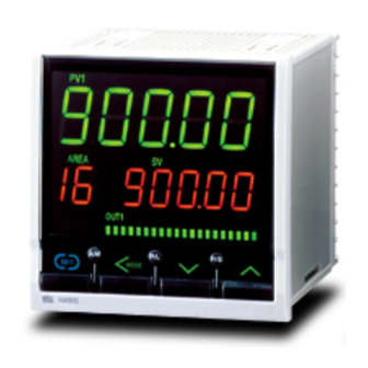
RKC INSTRUMENT HA430 Operation Manuals (176 pages)
Resin Pressure Digital Controller
Brand:
RKC INSTRUMENT
| Category:
Controller
| Size: 1 MB
Table of Contents
Table of Contents
7
1 Outline
15
Checking the Product
15
Model Code
16
Input/Output Functions
18
Parts Description
21
2 Mounting
24
Mounting Cautions
24
Dimensions
25
Ha430
25
Ha930
25
Procedures of Mounting and Removing
26
Mounting Procedures
26
Removing Procedures
26
3 Wiring
27
Wiring Cautions
27
Terminal Layout
28
Ha430
28
Ha930
28
Wiring of each Terminal
29
Power Supply
29
Output 1 to 3 (OUT1 to OUT3)
30
Output 4 to 5 (OUT4 to OUT5)
30
Input 1 (Pressure Sensor Input)
31
Input 1 (Voltage and Current Inputs)
32
Input 2 (Thermocouple, RTD, Voltage, and Current Inputs)
33
Remote Input (Optional)
33
Event Input (Optional)
33
Sensor Power Supply (Optional)
34
Communication (Optional)
34
4 Setting
36
Setting Procedure to Operation
36
Operation Menu
38
Input Type and Input Range Display
39
Key Operation
40
Scrolling through Parameters
40
Changing Set Value (SV)
40
Data Lock Function
41
How to Restrict Operation of the Direct Keys
41
Changing Parameter Settings
42
Change Settings
42
5 Sv Setting & Monitor Mode
44
Display Sequence
44
Procedure for Set Value (SV) Setting
45
6 Parameter Setting Mode
46
Display Sequence
46
Parameter List
48
Description of each Parameter
49
Event 1 Set Value (EV1) Event 2 Set Value (EV2) Event 3 Set Value (EV3) Event 4 Set Value (EV4)
49
Control Loop Break Alarm (LBA) Time (Lba1, Lba2)
49
LBA Deadband (Lbd1, Lbd2)
50
Proportional Band (1. P, 2. P) for PI/PID Control
51
Integral Time (1. I, 2. I) for PI/PID Control
51
Derivative Time (1. D, 2. D) for PID Control
51
Control Response Parameter (1. Rpt, 2. Rpt)
52
Setting Change Rate Limiter (Up) (1.Svru, 2.Svru)
52
Setting Change Rate Limiter (Down) (1.Svrd, 2.Svrd)
53
Area Soak Time (AST)
54
Link Area Number (Lnka)
55
7 Setup Setting Mode
56
Display Sequence
56
Parameter List
57
Description of each Parameter
58
PV Bias (1. Pb, 2. Pb)
58
PV Digital Filter (1. Df, 2. Df)
58
PV Ratio (1. Pr, 2. Pr)
58
PV Low Input Cut-Off (1. PLC, 2. PLC)
59
Proportional Cycle Time (1. T, 2. T)
59
Device Address (Slave Address) (Add2)
60
Communication Speed (Bps2)
60
Data Bit Configuration (Bit2)
60
Interval Time (Int2)
61
Infrared Communication Address (Add3)
61
Infrared Communication Speed (Bps3)
61
Auto-Zero (Azer)
62
Auto Calibration (ACAL)
63
Set Lock Level (LCK)
63
8 Engineering Mode
64
Display Sequence
64
Parameter List
68
Precaution against Parameter Change
72
Screen Configuration (F10)
77
STOP Display Selection (SPCH)
77
Bar Graph Display Selection (De)
77
Bar Graph Resolution Setting (Deut)
78
Decimal Point Position of MV Scaling (Mvdp)
78
MV Scaling High (MVHS)
78
MV Scaling Low (MVLS)
79
Direct Key (F11)
79
Auto/Manual Transfer Key Operation Selection (Fn1)
79
Remote/Local Transfer Key Operation Selection (Fn2)
79
RUN/STOP Transfer Key Operation Selection (Fn3)
79
Input 1 (F21)/Input 2 (F22)
80
Input Type Selection (1. Inp, 2. Inp)
80
Display Unit Selection (1. Unit, 2. Unit)
81
Gain Setting (Gain) [F21]
81
Linearize Type (Lins) [F21]
82
Shunt Resistance Output Value (Shnt) [F21]
82
Decimal Point Position (1. Pgdp
83
Input Scale High (1. PGSH
83
Input Scale Low (1. PGSL
84
Input Error Determination Point (High) (1. Pov, 2. Pov)
84
Input Error Determination Point (Low) (1. Pun, 2. Pun)
85
Burnout Direction (1. Bos, 2. Bos)
85
Square Root Extraction Selection (1. Sqr, 2. Sqr)
86
PV Hold Function (1. Hlds, 2. Hlds)
86
Power Supply Frequency Selection (Pfrq)
86
Event Input (F23)
87
Event Input Logic Selection (Disl)
87
Output (F30)
90
Output Logic Selection (Logc)
90
Output Timer Setting (Ott1 to Ott5)
91
Alarm Lamp Lighting Condition Setting (ALC1, ALC2)
91
Interlock Function (Otil)
92
Transmission Output 1 (F31)/ Transmission Output 2 (F32)
93
Transmission Output 3 (F33)
93
Transmission Output Type Selection (Ao1, Ao2, Ao3)
93
Transmission Output Scale High (AHS1, AHS2, AHS3)
93
Transmission Output Scale Low (ALS1, ALS2, ALS3)
93
Event 1 (F41)/Event 2 (F42)/Event 3 (F43)/Event 4 (F44)
94
Event Type Selection (ES1, ES2, ES3, ES4)
94
Event Hold Action (Eho1, Eho2, Eho3, Eho4)
96
Event Differential Gap (EH1, EH2, EH3, EH4)
97
Event Action at Input Error (Eeo1, Eeo2, Eeo3, Eeo4)
98
Event Assignment (EVA1, EVA2, EVA3, EVA4)
98
Control (F50)
99
Hot/Cold Start Selection (Pd)
99
Input 2_Use Selection (CAM)
99
SV Tracking (Trk)
100
Control 1 (F51) Control 2 (F52)
101
Control Action Type Selection (1. Os, 2. Os)
101
Integral/Derivative Time Decimal Point Position (1.Iddp, 2.Iddp)
101
Derivative Gain (1. Dga, 2.Dga)
101
ON/OFF Action Differential Gap (Upper) (1. Ohh, 2. Ohh)
102
ON/OFF Action Differential Gap (Lower) (1. Ohl, 2. Ohl)
102
Action at Input Error (High) (1.Aove, 2.Aove)
103
Action at Input Error (Low) (1.Aune, 2.Aune)
103
Manipulated Output Value at Input Error (1. PSM, 2. PSM)
104
Manipulated Output Value
104
When Transferred Auto from Manual (1. PSM, 2. PSM)
104
Output Change Rate Limiter (Up) (1. Oru, 2. Oru)
104
Output Change Rate Limiter (Down) (1. Ord, 2. Ord)
105
Output Limiter High (1. Olh, 2. Olh)
106
Output Limiter Low (1. Oll, 2. Oll)
106
MV Transfer Function (1. MVTS, 2. MVTS)
106
Autotuning 1 (AT1) (F53) Autotuning 2 (AT2) (F54)
107
AT Bias (1. Atb, 2. Atb)
107
AT Cycle (1. ATC, 2. ATC)
108
AT Differential Gap Time (1. ATH, 2. ATH)
109
AT Action (1. Att, 2. Att)
110
Communication Function (F60)
111
Communication Protocol Selection (CMPS2)
111
Set Value (SV) (F70)
111
Setting Change Rate Limiter Unit Time (Svrt)
111
Soak Time Unit Selection (Stdp)
111
Set Value 1 (SV1) (F71) Set Value 2 (SV2) (F72)
112
Setting Limiter High (1. SLH, 2. SLH)
112
Setting Limiter Low (1. SLL, 2. SLL)
112
PV Transfer Function (1. PVTS, 2. PVTS)
112
System Information Display (F91)
113
9 Operation
114
Control RUN and STOP
114
Operation under Control RUN Mode
114
Display at Control STOP
114
Configuration of Operation Mode
115
Monitoring Display in Operation
116
Auto/Manual Transfer
122
Auto/Manual Transfer by Front Key Operation
122
Auto/Manual Transfer by Direct Key (A/M) Operation
123
Auto/Manual Transfer by Event Input
123
Procedure for Setting the Manipulated Output Value (MV) in Manual Mode
124
Manipulated Output Value (MV) under Manual Control Is Changed by Event Input
124
Remote/Local Transfer
125
Remote/Local Transfer by Front Key Operation
125
Remote/Local Transfer by Direct Key (R/L) Operation
125
Remote/Local Transfer by Event Input
126
RUN/STOP Transfer
126
RUN/STOP Transfer by Front Key Operation
126
RUN/STOP Transfer by Direct Key (R/S) Operation
127
RUN/STOP Transfer by Event Input
127
Control Area Transfer
128
Control Area Transfer by Front Key Operation
128
Control Area Transfer by Event Input
128
Start Action at Recovering Power Failure
129
Ramp/Soak Control
130
10 Error Display
134
Over-Scale and Underscale
134
Self-Diagnostic Error
135
11 Troubleshooting
136
Display
136
Control
137
Operation
138
Other
139
12 Removing the Internal Assembly
140
APPENDIX A. Setting Data List
141
A-1. SV Setting & Monitor Mode
141
A-2. Setup Setting Mode
142
A-3. Parameter Setting Mode
145
A-4. Engineering Mode (F10 to F91
147
Specifications
164
Memory Area Data List
169
Index
171
Advertisement
RKC INSTRUMENT HA430 Instruction Manual (2 pages)
Resin Pressure Digital Controller
Brand:
RKC INSTRUMENT
| Category:
Controller
| Size: 0 MB
Table of Contents
1. Mounting
1
Mounting Cautions
1
Dimensions
1
Mounting Procedures
1
Removal Procedures
1
2. Wiring
1
Wiring Cautions
1
Terminal Configuration
1
Specifications
1
3. Parts Description
2
Area Display
2
Upper Display
2
Lower Display
2
Output/Alarm Lamp
2
Bar Graph Display
2
4. Operation Flow of each Mode
2
Operation Mode
2
Setup Setting Mode
2
Parameter Setting Mode
2
RKC INSTRUMENT HA430 Instruction Manual (2 pages)
Resin Pressure Digital Controller
Brand:
RKC INSTRUMENT
| Category:
Controller
| Size: 0 MB
Table of Contents
1. Mounting
1
2. Wiring
1
3. Parts Description
2
4. Operation Flow of each Mode
2
Advertisement
Advertisement
Related Products
RKC INSTRUMENT HA930 Series
RKC INSTRUMENT HA400 Series
RKC INSTRUMENT HA900 Series
RKC INSTRUMENT HA401 Series
RKC INSTRUMENT HA901 Series
RKC INSTRUMENT H-PCP-J
RKC INSTRUMENT CB Series
RKC INSTRUMENT CB100 Series
RKC INSTRUMENT CB100L
RKC INSTRUMENT CB103
RKC INSTRUMENT Categories
Temperature Controller
Controller
Media Converter
Measuring Instruments
Control Systems
More RKC INSTRUMENT Manuals
Login
Sign In
OR
Sign in with Facebook
Sign in with Google
Upload manual
Upload from disk
Upload from URL