Table of Contents
Advertisement
Quick Links
EPSOLAR
Thank you very much for selecting our product!
This manual offers important information and suggestions with respect
to installation, use and troubleshooting, etc. Please read this manual
carefully before using the product and pay attention to the safety
recommendations in it.
PATENTED PRODUCT, COUNTERFEITING NOT ALLOWED!
Advertisement
Table of Contents
Troubleshooting

Related Manuals for Epsolar ViewStar MT-100


Summary of Contents for Epsolar ViewStar MT-100
- Page 1 EPSOLAR Thank you very much for selecting our product! This manual offers important information and suggestions with respect to installation, use and troubleshooting, etc. Please read this manual carefully before using the product and pay attention to the safety recommendations in it.
- Page 3 ViewStar Solar Charge Controller Nominal system voltage 12V 24V 48V Nominal charge / discharge current 10A 20A 30A 40A 50A 60A Final interpretation right of the manual belongs to our company. Any changes without prior notice!
-
Page 4: Table Of Contents
Contents 1 Important Safety Information ..................1 2 General Information..................... 2 2.1 Product Overview ................... 2 2.2 Product Features ....................3 2.3 Optional Accessories ..................5 3 Installation Instructions ....................6 3.1 Mounting ......................6 3.2 Wiring......................8 4 Operation........................11 4.1 PWM Technology .................. -
Page 5: Important Safety Information
1 Important Safety Information Save These Instructions This manual contains important safety, installation and operating instructions. The following symbols are used throughout this manual to indicate potentially dangerous conditions or mark important safety instruction, please take care when meeting following symbols. -
Page 6: General Information
2 General Information Thank you for selecting ViewStar series solar charge controller that adopts the most advanced digital technique, displays on the LCD and operates fully automatically. The Pulse Width Modulation (PWM) battery charging and the unique control technology can greatly increase the lifetime of battery. -
Page 7: Product Features
2.2 Product Features VS1024(N) / VS2024(N) VS2048(N) / VS30**(N) / VS40**(N) / VS50**(N) / VS60**(N) - Page 8 1 Local temperature sensor It is used for acquisition of ambient temperature to undertake temperature compensation of charging and discharging parameters, when the remote temperature sensor is not connected Fault LED indicator An LED indicator that shows faults of solar system 3 Charging LED indicator An LED indicator that shows charging status 4 Liquid crystal display (LCD)
-
Page 9: Optional Accessories
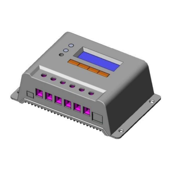
2.3 Optional Accessories 1. Remote Meter(Model MT-100) The digital Remote Meter displays system operating information, error indications, and self-diagnostics read-out. Information is displayed on a backlit LCD display. The large numerical display and icons are easy to read and large buttons make navigating the meter menus easy. -
Page 10: Installation Instructions
3 Installation Instructions 3.1 Mounting Read through the entire installation section first before beginning installation. Be very careful when working with batteries. Wear eye protection. Have fresh water available to wash and clean any contact with battery acid. Uses insulated tools and avoid placing metal objects near the batteries. Explosive battery gasses may be present during charging. - Page 11 Step 1: Choose Mounting Location Locate the controller on a vertical surface protected from direct sun, high temperature, and water. And make sure good ventilation. Step 2: Check for clearance Place the controller in the location where it will be mounted. Verify that there is sufficient room to run wires and that there is sufficient room above and below the controller for air flow.
-
Page 12: Wiring
3.2 Wiring NOTE: A recommended connection order has been provided for maximum safety during installation. NOTE: There are two types of the controller: common positive controller and common negative controller. CAUTION: Don t connect the loads with surge power exceeding the ratings of the controller. - Page 13 Controller s load terminals can be connected to DC electric equipments whose nominal operation voltage is the same as nominal voltage of battery. The controller supplies power to loads with battery voltage. It is suggested that positive pole or negative pole of battery and loads should be connected to a safety device, whose operation current is not twice lower than nominal charging or discharging current.
- Page 14 Step 1: Wiring and switching on After solar system is wired, check carefully all wirings so as to make it clear whether all 6 terminals are correctly connected and tightened. According to the order of switching on in the chart, battery first, loads second and solar module third successively to avoid nominal system voltage identification error.
-
Page 15: Operation
4 Operation 4.1 PWM Technology (Series Pulse Width Modulation) The controller adopts the advanced series pulse width modulation (PWM) charging mode. With range of 0-100%, it can charge the battery quickly and stably under any condition of solar photovoltaic system. PWM charging mode use automatic conversion duty ratio pulses current to charge the battery. - Page 16 ·Boost Charge When the battery has recharged to the Boost voltage setpoint, constant- current regulation is used to prevent heating and excessive battery gassing. The Boost stage remains 120 minutes and then goes to Float Charge. Every time when the controller is powered on, if it detects neither over discharged nor overvoltage, the charging will enter into boost charging stage.
-
Page 17: Hmi Interface
NOTE: Equipment damage! Over-charging and excessive gas precipitation may damage the battery plates and activate material shedding on them. Too high an equalizing charge or for too long may cause damage. Please carefully review the specific requirements of the battery used in the system. - Page 18 Buttons instruction Menu / Cursor left button Cursor up / Number add button Cursor down / Number reduce button Enter / cursor right button Charging indicator GREEN ON whenever sunlight is available for battery charging, Charging LED indicator Table 4-1 Color Indicator Charging Status...
-
Page 19: Operation And Displaying Of Controller
Fault LED indicator Table 4-2 Color Indicator Charging Status PV OverCurrent Measure Err MOS-I Short MOS-C Short MOS Break BATT OVD Error OverTemp Flashing LOAD Overload Short MOS Short Error DEVICE OverTemp 4.4 Operation and Displaying of Controller Load work mode 1. - Page 20 Operation and displaying of controller Initialization Interface When controller is powered on, it turns into initialization, refer to the following picture: WELCOME VERSION 1.1 Main Menu Interface When controller is initialized, it is automatically turned into monitoring interface. Press button to turn into main menu 1 interface which displays the following contents: 1 Monitoring...
-
Page 21: System Monitor Interface
System Monitor Interface In the main menu interface, when press , the inverse cursor moves between main menu 1 and main menu 2.When the inverse cursor rests at 1 Monitoring in the main menu 1 interface, press to enter into the system monitoring interface which displays contents as follows. - Page 22 Load voltage and current Press and then enter into the following interface which indicates real-time voltage and current of loads. LOAD 12.5V 5.5A Real-time clock and imaging system status Press and enter into the following interface which indicates real-time clock and imaging system status.
- Page 23 System status Press and enter into the following interface which indicates system status. PV : Disconnect BATT : NoCharge / Normal LOAD : On DEVICE : Normal PV status Connect Disconnect Measure Err Over Current MOS-I Short MOS-C Short MOS Break BATT status Equalize Boost...
-
Page 24: Device Setting Interface
Device Setting Interface In the main menu interface, press , the inverse cursor moves between interfaces of main menu 1 and main menu 2. When the inverse cursor 2 Device Set rests on in the main menu interface 1, press to enter into system setting interface which displays the following contents. - Page 25 Device Set Date : 05 - 2011 Save Cancel Time : 12 : 24 : 23 Backlight : 10 Mins If save confirmation is chosen, the system will automatically check the validity of parameters. If the parameters are reasonably set, the indication of successful saving will occur as follows.
-
Page 26: Charging And Discharging Parameters Setting Interface
Charging and Discharging Parameters Setting Interface In the main menu interface, when press , the inverse cursor moves between interfaces of main menu 1 and main menu 2. when the inverse cursor 3 Parameter Set rests on in main menu 1, press to enter into charging and discharging parameters setting interface whose displaying interface as follows. - Page 27 Control parameters interface Press continuously and the inverse cursor will enter into the control parameters interface. Press to modify the following control parameters. Parameter Set Over Volt. Disc : 16.0V Charg Lmt : 15.5V Over Volt. Rect : 15.0V Parameter Set If battery type is GEL, Equal Chrg : 14.6V the parameters cannot be...
- Page 28 Only when the inverse cursor moves to the option of discharging limit voltage, the modified parameters information can be saved. Press and the following picture appears. Press to choose save confirmation or save cancellation. After choosing confirmation, press again, the modified parameters will be saved or cancelled.
-
Page 29: Load Control Interface
Load Control Interface In the main menu interface, when press , the inverse cursor moves between the interfaces of main menu 1 and main menu 2. When the inverse cursor 4 Load Set rests on in main menu 1, press and enter load control interface with the following contents displayed. - Page 30 Press to choose ON or OFF. After confirmation, press and the following picture occurs. Push to choose save confirmation or save cancellation. After choosing confirmation, press again. So the modified parameters will be saved or cancelled. When it is cancelled, the inverse cursor moves back to the main menu interface.
- Page 31 When press , the inverse cursor moves among every parameters. When is continuously pressed, it moves back to main menu interface and press to modify every parameters. Only when the inverse cursor rests on option of light control off delay, can modification of the parameters be saved.
- Page 32 ight control + timer control interface Press to choose load control mode. When the inverse cursor Light On + Timer to enter into rests on in the load control interface, press light control plus time control interface. Light Timer Control On : 05.0 V Delay 10 m Off : 06.0 V Delay...
- Page 33 When save confirmation chosen, the indication of successful saving will occur as follows. After parameters successfully saved, it returns to main menu interface. Light Timer Control On : 06.0 V Delay 10 m SAVE SUCCESS Off : 05.0 V Delay 10 m Work Time : 10 : 00 : 00 sunrise time, the...
- Page 34 When choose Double as time control mode, it is double time interval control. Time Control 2 On Time : : 30 : 00 Off Time : 06 : 00 : 00 Double Single In the double time work mode, time2 could not be the same as time 1 when Setting. Single When choose as time control mode, it is single time interval control and only...
-
Page 35: Nominal Parameter Interface
When save confirmation chosen, the indication of successful saving will occur as follows. After parameters successfully saved, it returns to main menu interface. Time Control 2 On Time : 19 : 20 : 00 SAVE SUCCESS Off Time : 07 : 00 : 00 Double Single Nominal Parameter Interface... -
Page 36: Factory Reset Interface
Rated Value Batt : 12.0 V Save Cancel Load : 10.0A PV : 10.0A Type : Seal Flood When save confirmation chosen, the indication of successful saving will occur as follows. After parameters successfully saved, it returns to main menu interface. Rated Value Batt : 12.0 V SAVE SUCCESS... - Page 37 After confirmed, push , and the following picture appears. Press to choose save confirmation or save cancellation. After choosing confirmation, press again, and the modified parameters can be saved or cancelled. When save cancellation is chosen, the inverse cursor moves back to the main menu interface.
-
Page 38: Protection, Troubleshooting And Maintenance
5 Protection, Troubleshooting and Maintenance 5.1 Protection ·PV Array Short Circuit If PV array short circuit occurs, clear it to resume normal operation. ·Load Overload If the load current exceeds the maximum load current rating, the controller will disconnect the load. Overloading must be cleared up through reapply power or pressing the setting button. -
Page 39: Troubleshooting
5.2 Troubleshooting Trouble Shooting Table 5-1 Possible Faults reasons Troubleshooting Charging LED indicator Check that battery wire off during daytime when array connections are correct and tight. sunshine falls on PV disconnection modules properly. the PV of monitoring interface shows Disconnect. Charging circuit is off and Charging Please check whether solar panel array... - Page 40 Charging and discharging Battery over Measure and judge if the voltage of circuit is off and the BATT voltage battery is too high, and switch off the monitoring interface wiring of solar array. shows OVD. Charging and discharging Operating When operating ambient temperature or circuit is off and the BATT ambient monitoring...
- Page 41 times, push the key ENTER and controller recover output after 10 seconds. In the process of 5-time reactivation, if it is recovered manually, the 5-time reactivation will be circulated again. When there is any change from night to daytime, restart the self-recovery process. Namely, 5-time circular reactivation can be operated again.
-
Page 42: Maintenance
Charging and discharging Cooling fins When the temperature of cooling fins of circuit is off and the controller LOAD monitoring over controller reach 85 , the controller will interface shows OverTemp. temperature cut input and output circuit; when it is lower than 75 ,the controller will automatically recover the connection of input and output circuit. -
Page 43: Warranty
Notes: Dangerous with electric shock! Make sure that all power source of controller is cut off when operate above processes, and then make inspection or other operations 6 Warranty The ViewStar charge controller is warranted to be free from defects for a period of TWO (2) years from the date of shipment to the original end user. -
Page 44: Technical Specifications
7 Technical specifications Model NO 1024 2024 3024 4024 5024 6024 Electrical Parameters Nominal System Auto work Voltage Maximum Battery Voltage Maximum PV Voltage Rated Battery Current Charge Circuit Voltage Drop Discharge Circuit Voltage Drop Self-consumption 18mA Communication TTL232 level / RJ45 interface Remote temperature 2ERJ 3.81... - Page 45 Model NO 2048 3048 4048 5048 6048 Electrical Parameters Nominal System Auto work Voltage Maximum Battery Voltage Maximum PV Voltage Rated Battery Current Charge Circuit Voltage Drop Discharge Circuit Voltage Drop Self-consumption 18mA Communication TTL232 level / RJ45 interface Remote temperature 2ERJ 3.81 sensor interface...
- Page 46 Only suitable for acid battery Sealed Flooded Charging Parameters Upperlimit Over Voltage Lowerlimit Disconnect Voltage Default Upperlimit Charging Limit Lowerlimit Voltage Default Upperlimit Over Voltage Lowerlimit Reconnect Voltage Default Upperlimit Equalize Charging Lowerlimit Voltage 14.6V ;x2/24V 14.8V ;x2/24V Default Upperlimit Boost Charging Lowerlimit...
- Page 47 Upperlimit Under Voltage Warning Reconnect Lowerlimit Voltage Default Upperlimit Under Voltage Lowerlimit Warning Voltage Default Upperlimit Voltage Lowerlimit Disconnect Voltage Default Upperlimit Discharging Limit Lowerlimit Voltage Default Equalize Duration 2 hours Boost Duration 2 hours Hreshold Voltage Parameters Upperlimit DTTV (Day Time Lowerlimit Threshold Voltage) Default...
- Page 48 mm(inches) 150(5.9) 162(6.38) VS1024(N) Dimensions 150(5.9) 162(6.38) VS2024(N) Dimensions...
- Page 49 191(7.52) 200(7.87) VS2048(N) & VS3024(N) Dimensions 191(7.52) 201(7.91) VS3048(N) & VS4024(N) Dimensions...
- Page 50 195(7.68) 205(8.07) VS4048(N) & VS5024(N) Dimensions 195(7.68) 205(8.07) VS5048(N) & VS6024(N) Dimensions...
- Page 51 VS6048(N) Dimensions...
- Page 54 Version number: V6.0...
- Page 56 BEIJING EPSOLAR TECHNOLOGY CO., LTD. Tel 010-82894112 / 82894962 Fax 010-82894882 E-mail info@epsolarpv.com Website: www.epsolarpv.com...
Need help?
Do you have a question about the ViewStar MT-100 and is the answer not in the manual?
Questions and answers